Table of Contents
Advertisement
Quick Links
Advertisement
Table of Contents

Related Manuals for Hog Technologies HT1000

Summary of Contents for Hog Technologies HT1000
- Page 1 GROUND Operations Manual...
-
Page 3: Table Of Contents
1.3 Hose Safety .......................16 1.4 High Pressure Fitting Safety..................16 Section 2: HT1000 Components 2.1 HT1000 Overview ......................19 2.2 Hog Head ........................20 2.3 Hydraulic Motor & Rotating Spray Bar ................22 2.4 Thru-Shaft, Spray Bars & Nozzles ..................23 2.5 Hydraulic Hoses, UHP Hoses & Electrical Cables ...............27 2.6 Vacuum Hose ......................30... - Page 4 Ground Hog Spare Parts Kit ....................76 Appendix 4: Pre-Op Checklist Pre-Op System Check List ....................77 Appendix 5: Glossary Of Terms Hog Technologies Glossary of Terms ..................79 Appendix 6: Specifications Ground Hog Specifications ....................83 Appendix 7: Nozzle & Spray Bar Configuration Nozzle Configuration Chart....................85...
-
Page 5: Welcome
WELCOME Thank you for purchasing the HT1000. We know that you have other options available to you and con- sider it a blessing that you chose our product. We affectionately nicknamed this unit the Ground Hog SR. This compact Hog Tool is best known for its reliability, user-friendly features, and simple quality. - Page 6 NOTES...
-
Page 7: Warranty
Hog Technologies warrants its components to be free from defects in material and workmanship while under normal use and service. Hog Technologies will, at its option, either repair or replace free of charge any such part that appears to us to be defective in material or workmanship during the warranty period. - Page 8 NOTES...
-
Page 9: Caution & Warning Labels
IMPROPERLY. IMPORTANT NOTE: Every precaution has been taken by Hog Technologies to reduce the risks associated with possible injury and damage from electrical faults, high pressure water and hydraulic components or mechani- cal failure. However, your own precaution and good maintenance procedures are necessary in order to maintain a safe working environment. - Page 10 BEFORE ATTEMPTING TO CONNECT, OPERATE, OR REPAIR THIS EquIPMENT, THOROuGHLY REAd THESE INSTRuCTIONS ANd ANY SAFETY WARNING OR INSTRuCTION PAMPHLETS INCLudEd WITH YOuR SHIPMENT. FOR ANY quESTIONS CONCERNING SAFE OPERATION ANd MAINTENANCE PROCEduRES, CONTACT YOuR HOG TECHNOLOGIES REPRESENTATIvE PRIOR TO uSE. (772) 223-7393 OR (877) 964-7312 HOG TECHNOLOGIES...
-
Page 11: Safety Information
90 dB 8.0 hours equipment operation manuals and instructions 92 dB 6.0 hours prior to using any Waterblasting product. Contact Hog Technologies (877-HOG ROAD) should any 95 dB 4.0 hours questions arise. 97 dB 3.0 hours Major Component Operation Manuals 100 dB 2.0 hours... -
Page 12: Blasting Safety
SOME HOG TECHNOLOGIES EquIPMENT uSES INTERNAL COMBuSTION ENGINES ANd FLAMMABLE FuEL. EvERY ing used and never exceed the service rating of PRECAuTION HAS BEEN TAKEN BY HOG TECHNOLOGIES the weakest component. This system is designed TO REduCE THE RISKS ASSOCIATEd WITH POSSIBLE... - Page 13 Section 1 - Safety Information Check Control Components by the high pressure stream. Waterblasting tool operators must be equipped with the following; Check all controls, switches and control panel heavy duty, steel toed, non-skid knee high boots, devices to ensure each is working properly before a heavy duty, protective rain suit, gloves, hard hat beginning operations.
- Page 14 Section 1 - Safety Information Use the Minimum Pressure Required CAUTION Do not exceed the operating pressure of the sys- tem’s lowest pressure-rated component. All equip- TO AvOId POSSIBLE INJuRY ANd dAMAGE TO EquIPMENT, ment pressure rating and warning tags should be u S E O N LY T H O R O u G H LY T R A I N E d P E R S O N N E L TO left intact.
- Page 15 Section 1 - Safety Information on threads only, never on the seat of the nozzle. 1.2 Nozzle Safety Inspect the seat area on nozzle to ensure a tight Check Flow Rating seal. If it is damaged, do not use. Combined nozzle flow rate must be compatible with the pump discharge and pressure rating.
-
Page 16: Hose Safety
Section 1 - Safety Information D) When using a tractor or a hog tool, always op- 1.3 Hose Safety erate the equipment well within the maximum General distance to avoid straining or damaging hoses. Ultra-High Pressure hoses are tough, but not in- vincible. - Page 17 Section 1 - Safety Information DANGER AN INJuRY CAuSEd BY HIGH PRESSuRE WATERJETS CAN BE SERIOuS. YOu SHOuLd REAd THIS WARNING STATEMENT CAREFuLLY ANd ALWAYS CARY THE MEdICAL INFORMATION CARd WITH YOu. • IN THE EvENT OF ANY WATERJET INJuRY: •...
- Page 18 NOTES...
-
Page 19: Ht1000 Components
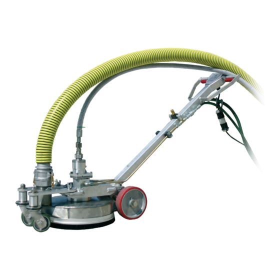
Section 2: HT1000 Components HT1000 Ground Hog the spray bar thru-shaft motor and the valve that 2.1 HT1000 Overview turns high pressure water ON and OFF. The Ground Hog is a walk behind, Ultra High Pres- sure waterblasting tool equipped with a rotating The Ground Hog is designed for operating pres- spray bar. -
Page 20: Hog Head
Section 2 - Components valves that control Ground Hog functions sepa- rately. The Waterblasting HT500 Hog Pack is an available option that can be used with power Wing Nut systems that don’t include a hydraulic system. NOTICE: IF YOu INTENd TO uSE A NON WATERBLASTING POWER S Y S T E M, Y O u S H O u L d C O N TA C T WAT E R B L A S T I N G CuSTOMER SERvICE dETERMINE IF THE uNIT WILL ACCOMMOdATE HOG TOOL OPERATION ANd/OR FOR THE... - Page 21 Section 2 - Components Wear Brush A wear brush clamped to the blasting head shroud provides a partial seal between the blasting head and pavement. The wear brush regulates vacuum air flow into the shroud and reduces the amount of debris and water exiting the blasting head dur- ing operations.
-
Page 22: Hydraulic Motor & Rotating Spray Bar
HEAd ROTATION SPEEdS EXCEEdING 3000 RPM WILL dAMAGE THE BEARINGS ANd THRu-SHAFT MOTOR. dAMAGE CAuSEd BY EXCESSIvE RPM WILL NOT BE COvEREd BY THE HOG TECHNOLOGIES WARRANTY. The tapered bearing at the upper end of the thru- shaft motor is equipped with a grease fitting and The spray bar is attached to a thru-shaft that runs requires grease at the start of each day. -
Page 23: Thru-Shaft, Spray Bars & Nozzles
Section 2 - Components Swivel Seal & Brass Backup Ring Swivel Nut Swivel Seal Weep Hole Typical Thru-Shaft Motor Components Thru-shaft Cover Grease Fitting Speed Sensor Brass Backup Ring Swivel Seal system is pressurized indicates the seal is leak- 2.4 Thru-Shaft, Spray Bars & Nozzles ing and must be replaced. - Page 24 The type of road surface. (Concrete or asphalt) PRESSuRE TO SPIKE EXCESSIvELY CAuSING dAMAGE TO COMPONENTS OR RuPTuRE dISCS ON THE uHP PuMP TO • Profile requirements per job specifications. BuRST. Hog Technologies offers a variety of spray bar configurations to meet requirements of all types...
- Page 25 Section 2 - Components Spray Bar Protector Each spray bar is equipped with a spray bar pro- tector that is held in place with one or two cotter pins. The spray bar protector shields the nozzles and spray bar from damage caused by debris dur- ing blasting operations.
- Page 26 You can also water being used. Any dirt or debris in the system contact Hog Technologies Customer Support toll can clog a nozzle orifice causing a spike in the high free at (877) HOG-ROAD for assistance in select-...
-
Page 27: Hydraulic Hoses, Uhp Hoses & Electrical Cables
UHP completely avoided and that the hoses and elec- pump’s maximum operating pressure. We recom- trical cables are properly protected to reduce mend that you only use nozzles, high pressure chaffing. hoses and fittings supplied by Hog Technologies... - Page 28 Tool when it is connected to a Waterblasting power unit. If replacement hoses are required, you should only use hoses from Hog Technologies or hoses with the same specifications as the originals. When connecting hydraulic hoses, always make sure the fittings are clean before making the con- nection.
- Page 29 Section 2 - Components UHP Hoses The condition of the high pressure water hoses is critical to the proper operation of the Ground Hog. It is important that they be stored and handled properly to ensure they are not damaged or kinked during deployment and storage.
-
Page 30: Vacuum Hose
54,000 PSI (3,723 Bar). To ensure you are using the correct hoses, we recommend that you only use hoses purchased from Hog Technologies. Retire a UHP Hose from Service if: A) Cover is damaged and reinforcing wires are exposed to rust and corrosion;... -
Page 31: Ground Hog Control Systems
TO EquIPMENT ANd INJuRY OR dEATH TO PERSONNEL HIT BY THE TOOL. Hydraulic control valves on manifolds manufactured by Hog Technologies are equipped with a by-pass NEvER OPERATE THE GROuNd HOG OR ANY OTHER HOG TOOL WITH HIGH PRESSuRE WATER SuPPLIEd WHEN THE... - Page 32 Section 2 - Components Spray bar rotation speed is controlled by open- ing or closing the needle valve on the handle that NOTICE: restricts hydraulic fluid flow. Rotate the valve ALL OPERATORS ANd SuPPORT PERSONNEL SHOuLd REAd THE MANuAL INCLudEd WITH THE uLTRA HIGH counterclockwise to open the valve and increase PRESSuRE ANd vACuuM POWER SYSTEM TO MAKE rotation speed.
-
Page 33: Waterblasting Operations
Section 3: Waterblasting Operations Ground Hog Connected To A Trailer Mounted Waterblasting UHP & Vacuum Power System - Ready For Operation leaks, wear and deterioration. The inspection should 3.1 Startup/Shutdown Introduction be conducted in an orderly and consistent fashion A thorough understanding of the power system and to ensure all critical points are inspected each time. -
Page 34: Equipment Setup
Section 3 - Operation The following instructions provide a general over- 3.2 Equipment Setup view and introduction to the pre-operation (Pre- 1. Position the power system as close to the work Op) inspection. The Pre-Op Checklist provides area as possible. Make sure the location is level an itemized checklist that should be used when and protected from vehicle and foot traffic or performing a pre-operation inspection. - Page 35 Section 3 - Operation Startup Procedure 1. Make sure the Ground Hog control levers and thru-shaft motor control valve are in the OFF position or set to 0.. 2. If the Ground Hog UHP hoses have been re- connected since the last operation, the UHP system will need to be purged.
-
Page 36: Ground Hog Operating Guidelines
4. Raise engine speed to the operation RPM and set the pressure (refer to Section 3.3) Hog Technologies offers an on-site training pro- gram that dramatically reduces the learning curve 5. If necessary, activate the vacuum system. - Page 37 Section 3 - Operation Do’s • Always shutdown the power system before leaving the Ground Hog unattended or passing • Only allow trained personnel to operate the it to another person. Ground Hog and waterblasting equipment. • Allow the vacuum system to operate for a •...
-
Page 38: Routine Shutdown
Section 3 - Operation 3.5 Emergency Shutdown WARNING In addition to the Ground Hog operator, a support person should be monitoring the operation of the THE FORCE FROM THE BLASTING HEAd CAN EXCEEd 50 Ground Hog and UHP support system whenever LBS, CAuSING LOSS OF CONTROL ANd/OR THE BLAST TO waterblasting operations are underway. -
Page 39: General Maintenance
Section 4: General Maintenance 4.1 Lubrication & General Maintenance Introduction Lubrication Points You should become familiar with the location of all grease fittings as they require frequent lubrica- tion. The thru-shaft bearing requires specialized lubricant. Refer to the Maintenance Matrix chart in the Scheduled Maintenance section in this manual and component manufacturer’s operating and/or maintenance manuals for lubricant specifications... -
Page 40: Lubrication
Section 4 - Maintenance Ground Hog Lubrication Points A. Grease Thru-Shaft Bearing C. Grease Front Wheels B. Grease Front Casters D. Grease Rear Wheels 4.2 Lubrication The lubrication points shown in the photo provides a guide to the location of the lubrication points on your Ground Hog. -
Page 41: General Inspection & Maintenance
Section 4 - Maintenance Ground Hog Components A. Handles and Control Lever F. Thru-shaft motor Grease Fitting & Pressure Relief Hole B. Hydraulic Hose Connections G. Wear Brush and Wear Brush Clamp C. Spray Bar Speed Control Valve H. Vacuum Hose Connection D. - Page 42 Section 4 - Maintenance Ground Hog UHP System Components Daily: • Check all hoses and fittings for leaks and proper operation. Repair or replace leaking or malfunctioning components before operating the system. • Test UHP system under high pressure by acti- vating the control lever to turn high pressure ON &...
-
Page 43: Wear Brush Replacement
Section 4 - Maintenance 4.4 Wear Brush Replacement The Ground Hog wear brush bristles will slowly wear during operation. Consequently, the wear brush will require adjustment periodically to keep the bristles in contact with the pavement to pro- vide proper vacuum air flow. It will also need to be adjusted when the shroud and/or wear brush is replaced. -
Page 44: Dirt Shield Replacement
Section 4 - Maintenance 4.5 Dirt Shield Replacement The dirt shield should be inspected daily to ensure it is tightened properly and that the felt seal is in dirt Shield good condition. Apply Anti-Seize Button Seal Use the following procedure to replace a damaged or worn felt seal: 1. -
Page 45: Nozzle Installation
1. Make sure the waterblasting system is shut- down with the power system in the service position. Typical HT1000 Spray Bay Without Spray Bar Protector 2. Remove the spray bar protector cotter pin and the spray bar protector. 6. Once the spray bar is flushed, deactivate the 3. - Page 46 Section 4 - Maintenance 9. Tighten each nozzle finger tight, then torque to 10 ft lbs. 10. Reactivate the waterblasting system by follow- ing the steps in the Startup Procedure. 11. Follow the steps in the Startup Procedure to pressure test the spray bar and nozzles. 12.
-
Page 47: Swivel Seal Replacement
Section 4 - Maintenance Thru-Shaft Cover Housing & Swivel Nut Swivel Tit In Thru-shaft Cover Housing 4.7 Swivel Seal Replacement The swivel seal must be inspected at the start of each shift and replaced at the first sign of leakage to avoid damage to the swivel nut and thru-shaft cover housing. - Page 48 Section 4 - Maintenance 5. Once the brass back-up ring is removed, in- 9. Install the brass back-up ring onto the swivel spect the swivel seal seat and the edges of tit with the beveled seat facing up. Make sure the seat in the back-up ring closely.
-
Page 49: High Pressure Hose Installation
Section 4 - Maintenance 4.8 High Pressure Hose Installation The ultra-high pressure hoses should be inspected weekly or every 50 hours and replaced as re- quired. Use the following procedure when replac- ing a pressure hose. When replacing damaged or worn high pressure hoses, check the burst rating marked on the hose. -
Page 50: Vacuum Hose Replacement & Rotation Procedure
Section 4 - Maintenance 4.9 Vacuum Hose Replacement & Rotation Procedure Debris buildup, kinks, clogs or leaks in the system will cause a reduction in airflow at the blasting head, reducing the efficiency of operation or causing opera- tions to stop completely. Debris buildup inside the hoses can be removed by periodically tapping the outside walls with a dead blow hammer while the system is operating at maximum vacuum. -
Page 51: Shroud Installation
Section 4 - Maintenance dirt Shield Apply Anti-Seize Button Seal Shroud Installed Spray Bar & Dirt Shield Components 4.10 Shroud Installation If the shroud becomes damaged, it must be re- placed following the steps outlined in this section. Removing the shroud: 1. - Page 52 Section 4 - Maintenance Installing a new shroud: 1. Clean the bottom of the thru-shaft motor hous- ing of dirt and debris. 2. Place the new shroud on the housing and align the bolt holes. Insert the shroud bolts and tighten finger tight.
-
Page 53: Thru-Shaft Motor Bearing Pre-Load
Section 4 - Maintenance 4.11 Thru-Shaft Motor Bearing Pre-Load Introduction nut. The spanner nut threads onto the thru-shaft and rests on top of the thrust bearing. By turn- The thru-shaft assembly is a key component in ing the spanner nut clockwise, we can raise the the Stripe Hog system. - Page 54 Section 4 - Maintenance Tools and Materials Required Tools Supplies 2 - Medium Sized Flat Blade Screwdrivers • Anti-Seize 1 - Medium Sized Channel Lock Pliers • Grease Gun and Mobile Poly Rex EM Grease 1 - 3/4” (19 mm) Open End Wrench •...
- Page 55 Section 4 - Maintenance Pressure Hose Figure 1: High pressure hose on top of the thru-shaft motor Figure 2: High pressure hose removed Step 1 Remove the High Pressure Hose Remove the high pressure hose from the top of the thru-shaft motor by turning the hand nut at the base of the hose counterclockwise.
- Page 56 Section 4 - Maintenance Figure 5: Use two medium flat head screwdrivers to remove the thrust housing cap. Note that the bolts are loose and left in place to prevent thrust housing cap from falling and being damaged during removal. Step 3 Remove Thrust Housing Cap Use a 6mm Allen wrench and a cross pattern to remove the 6 Allen head bolts that secure the thrust...
- Page 57 Section 4 - Maintenance Swivel Tit Assembly Gland Nut Figure 7: Swivel Tit gland nut to be removed by turning counterclockwise with a 15/16” deep well socket or box end wrench. Step 4 Remove Swivel Tit Assembly/Gland Nut While holding the thru-shaft with the 3/4” (19mm) open end wrench through the slot in the motor base, use a 15/16 (24mm) deep well socket or box end wrench to remove the swivel tit gland nut...
- Page 58 Section 4 - Maintenance Jam Nut Spanner Nut Figure 9: Jam nut and seal nut. Make sure to loosen Jam Figure 10: Use spanner to turn spanner nut. nut 4 full turns first. Step 5 Loosen Jam Nut and Set the Bearing Preload Thrust Housing Cap Bolts Insert the Spanner Tool and center on the Thrust Housing Cap Bolt holes.
- Page 59 Section 4 - Maintenance WARNING WHEN LOOSENING THE SPANNER SOCKET ANd SEAL NuT ONE BOLT HOLE TO SET THE BEARING PRELOAd OR WHEN TIGHTENING THE JAM NuT, IT IS CRITICAL THAT THE THRu-SHAFT IS HELd FIRMLY WITH THE 3/4” (19MM) OPEN ENd WRENCH SO THAT IT dOES NOT MOvE AT ALL.
- Page 60 Section 4 - Maintenance O-ring Seal Swivel Tit Assembly/Gland Nut RPM Sensor RPM Sensor Figure 13: O-ring seal seat at the top of the thru-shaft Figure 14: Swivel tit assembly/gland nut installed on the greased and the threads below the seal coated thru-shaft and torqued to 50 Ft lbs.
- Page 61 Section 4 - Maintenance Figure 15: Inspect and grease the O-ring seal on the thrust Figure 16: Apply anti-seize to the thrust housing bolts and housing cap. tighten them in a crisscross pattern to snug using a 6 mm Allen wrench. Step 9 Install The Thrust Housing Cap.
- Page 62 Section 4 - Maintenance Pressure Water Hose Hand Nut Grease Fitting Relief Hole Figure 17: Apply anti-seize to the thrust housing threads Figure 18: Thru-shaft bearing grease fitting and grease and install the high pressure water line. relief holes in thrust housing base. Step 10 Install the High Pressure Water Hose and Grease the Thru-Shaft Bearings.
- Page 63 Section 4 - Maintenance Step 11 Run the Thru-Shaft Motor Without Water Pressure, Then Under Full Water Pressure. Remove all tools and materials from the hog head and raise it to the full up position. Activate the hydraulic system and run the thru- shaft motor at maximum rpm for 15 minutes.
- Page 64 NOTES...
-
Page 65: Hog Tool Maintenance Matrix
Section 4 - Maintenance 4.12 Hog Tool Maintenance Matrix EQUIPMENT COMPONENT INTERVALS LUBRICANT SPECIFICATIONS Ground Hog Thru-shaft motor Bearings Daily Mobil PolyRex EM Grease No Substitutes Ground Hog Chassis Wheels and Casters Daily General Multi Purpose Grease This chart is a guide only. It should never be used to supersede equipment manufacturer’s specifications. - Page 66 NOTES...
-
Page 67: Appendix 1: Schematics
Appendix 1: Schematics Hog Head Thru-Shaft Assembly - 1... -
Page 68: Hog Head Thru-Shaft Assembly - 2
Appendix 1 - Schematics Hog Head Thru-Shaft Assembly - 2... -
Page 69: Hog Head Thru-Shaft Assembly - 3
Appendix 1 - Schematics Hog Head Thru-Shaft Assembly - 3... -
Page 70: Hog Head Thru-Shaft Assembly - 4
Appendix 1 - Schematics Hog Head Thru-Shaft Assembly - 4... -
Page 71: Appendix 2
Appendix 2: Troubleshooting Guide Water Blasting System Troubleshooting PROBLEM CAUSE AND SOLUTION Noise & Vibration Hog Head noisy. • Spray bar rotation extremely high. Turn speed control valve knob counterclockwise to reduce head speed. • Spray bar is hitting shroud (1). Shroud is bent or damaged. - Page 72 Appendix 2 - Troubleshooting PROBLEM CAUSE AND SOLUTION High Pressure Blasting System Water dripping from hose fitting indicator • Fitting Loose. Tighten fitting or replace hose and port. fitting. • Fitting is damaged. Replace hose and fitting. Water dripping from spray Bar and spray •...
- Page 73 Appendix 2- Troubleshooting PROBLEM CAUSE AND SOLUTION Vacuum System Vacuum loss or failure. • Vacuum blower is not engaged. Activate power system vacuum blower. • Vacuum system on power supply has a problem and is not operating properly. Troubleshoot and repair vacuum system on power supply.
- Page 74 NOTES...
-
Page 75: Appendix 3
Appendix 3: Tools & Spare Parts Mobile Tool System... -
Page 76: Ground Hog Spare Parts Kit
Appendix 3 - Tools & Spare Parts Ground Hog Spare Parts Kit Hog Technologies offers a spare parts kit for the Ground Hog waterblasting Tool. This comprehensive kit includes all parts and seals that routinely need to be replaced. The parts kit is available at www.striphogsupport.com or by contacting Waterblasting Customer Service. -
Page 77: Appendix 4
Appendix 4: Pre-Op Checklist PRE-OP CHECK LIST Mobile Spare Parts and Tool System Hog Head & Spray Bars F Mobile Spare Parts System Complete F Caster Wheels In Good Condition F Mobile Tool System Complete F Spray Bar & Nozzles Correct F Nozzles Grade 4 Or Better F Spray Bar Cover In Place Fluid Levels... - Page 78 NOTES...
-
Page 79: Appendix 5
Appendix 5: Glossary Of Terms Waterblasting Glossary of Terms 1 Micron Cartridge Filter - Traps smaller particles that may come from the clean water tank and pass through the charge pump. 10 Micron Bag Filter – Traps larger particles that may come from the clean water tank and pass through the charge pump. - Page 80 Appendix 5 - Glossary Of Terms Cutoff Ball Valve – Located inside the debris tank as a safety feature to stop the flow of vacuum if the tank becomes full. Debris Tank – Collects all debris removed from the road surface through the vacuum hose. Dirt Shield –...
- Page 81 Standoff Distance – Distance from the spray bar to the surface. Stripe Hog – Ultra high pressure water blasting equipment manufactured by Hog Technologies to remove paint and rubber from road surfaces. Supply Valve – Located between the clean water tank and the charge pump that is used to control the flow of water.
- Page 82 Appendix 5 - Glossary Of Terms T-Handle Pin Lock System – Used on the 5-axis hog arm as a safety feature to prevent the hog arm from drifting downward while the truck is in Drive Mode. Thru-Shaft – Hydraulic thru-shaft motor that connects and rotates the spray bar on the hog head assembly.
-
Page 83: Appendix 6: Specifications
Appendix 6: Specifications Ground Hog Specifications OPERATING PRESSURE ______________________________________ 40,000 psi (2750 bar) FLOW RATE ___________________________________________ 6.5-9.2 gallons (25-35 liters) CUTTING PATH ______________________________________________________14” (.36 m) WEIGHT _______________________________________________________ 105 lbs (47.6 kg) CLEANING CAPACITY ____________________________ 500-1,500 ft 2/hr (46.5-139.4 m 2/hr) VACUUM ______________________________________ Demand 800 CFM (22.7 cubic meters) MAXIMUM SPRAY BAR ROTATION SPEED ________________________________ 3000 RPM CONSTRUCTION _____________________________________ Aluminum, Stainless and Steel... - Page 84 NOTES...
-
Page 85: Nozzle & Spray Bar Configuration
Appendix 7: Nozzle & Spray Bar Configuration Nozzle Configuration Chart SPRAY BAR CONFIGURATION CHARTS FOR ALL MODELS THE GPM IN EACH SETUP IS CALCULATED PER SPRAY BAR 1-877-HOG-ROAD WWW. STRIPEHOGSUPPORT.COM... -
Page 86: Spray Bar Configuration Charts
Appendix 7 - Spray Bar & Nozzle Configuration Spray BAR Configuration Charts 6”, 14 Nozzle Spray Bar - 4” lines - Medium Aggressive 4.48 GPM @ 36K PSI / 4.74 GPM @ 40K PSI 6”, 14 Nozzle Spray Bar - 4” lines - Most Aggressive 4.54 GPM @ 36K PSI / 4.8 GPM @ 40K PSI 1-877-HOG-ROAD WWW. - Page 87 Appendix 7 - Spray Bar & Nozzle Configuration 8” Medium Aggressive Set Up 4.46 GPM @ 36K / 4.73 GPM @ 40K PSI 8” Most Aggressive Set Up 4.68 GPM @ 36K / 4.95 GPM @ 40K PSI 07 07 13 13 1-877-HOG-ROAD WWW.
- Page 88 Appendix 7 - Spray Bar & Nozzle Configuration 8” & 10”, 16 Nozzle - Least Aggressive Set Up 4.42 GPM @ 36K PSI / 4.68 GPM @ 40K PSI 8” & 10”, 16 Nozzle - Medium Aggressive Set Up 4.48 GPM @ 36K PSI / 4.74 GPM @ 40K PSI 8”...
- Page 89 Appendix 7 - Spray Bar & Nozzle Configuration 14”, Least Aggressive Set Up 4.61 GPM @ 36K PSI / 4.88 GPM @ 40K PSI 11 11 09 09 09 09 09 11 11 14”, Medium Aggressive Set Up 4.64 GPM @ 36K PSI / 4.91 GPM @ 40K PSI 13 11 09 09 07 07 07 07...
- Page 90 Appendix 7 - Spray Bar & Nozzle Configuration 14”, 22” & 36”, 30 Nozzle - Rubber Removal and/or Curing Compound Removal - 30K to 33K PSI 07 07 07 07 07 07 07 07 07 07 07 07 8” & 10”, 16 Nozzle - Curing Compound Removal Set-Up - Set Up - 25K - 35K PSI 1-877-HOG-ROAD WWW.
-
Page 91: Nozzle Calculation Sheet
Appendix 7 - Spray Bar & Nozzle Configuration Nozzle Calculation Sheet 1-877-HOG-ROAD WWW. STRIPEHOGSUPPORT.COM... - Page 92 NOTES...
-
Page 93: Appendix 8
CUSTOMER SERVICE HOT LINE - (001) (772) 214-1714 www.hogtechnologies.com www.stripehogsupport.com Hog Technologies will not be responsible for damages or loss caused by sub- stituted parts purchased locally or from another vendor or manufacturer. WARNING NEvER ATTEMPT TO uSE COMMONLY AvAILABLE PLuMBING PARTS, FITTINGS, ANd HOSES IN... - Page 94 Appendix 8 - Customer Support Stripe Hog Support Web Site Stripe Hog Customer Support Center Home Training Ambassador Club Marketing Stripe Hog Store Contacts You are here Home Mike Logout Typical Registration & Log On Window Welcome to the Stripe Hog Support (001) 772-223-7393 This number that will find an Center! available customer support representative 24/7.
- Page 96 3321 SE Slater Street Stuart, Florida 34992 (001) (772) 214-1714 P (001) 772-223-5461 F www.hogtechnologies.com Print Date 01/23/2019 Rev 1...
Need help?
Do you have a question about the HT1000 and is the answer not in the manual?
Questions and answers