Advertisement
Quick Links
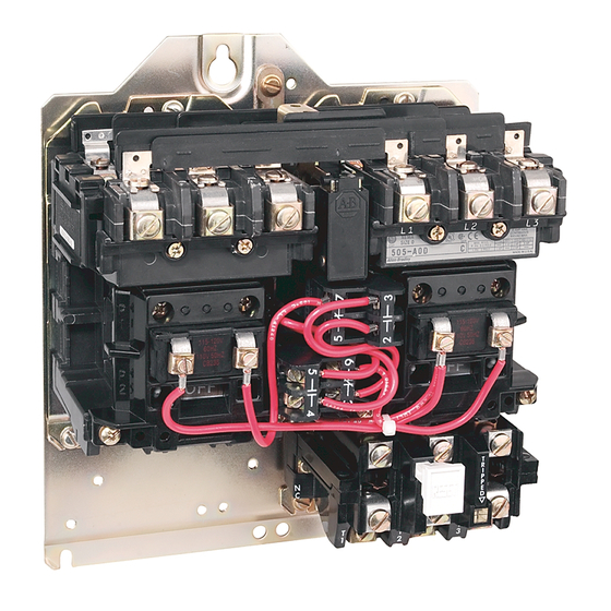
OPERATION
- Bulletin 505 starters are most commonly
used for full voltage starting and reversing of poly-
phase squirrel cage motors.
Bulletin 505 starters consist essentially of a "for-
ward" and a "reverse" contactor mounted to a com-
m o n b a s e . T h e s e c o n t a c t o r s a r e e l e c t r i c a l l y a n d
mechanically interlocked to guard against both contac-
tors closing at the same time.
Starters are equipped with Bulletin 592 block type
manual reset overload relays.
OPERATING ENVIRONMENT
be maintained in a clean and dry condition for depend-
able operation. Choice of the proper NEMA enclosure
type for the application is very important.
REPAIRS-starters
can be disassembled as depicted in
the "exploded" illustration on Page 4. Additionally the
following procedures and techniques are suggested to
aid in the sequential disassembly and reassembly of a
motor starter.
WARNING
- Before part replacements are at-
t e m p t e d t h e P O W E R S O U R C E M U S T B E
DISCONNECTED.
NOTE
- If parts are removed from both contactors,
keep them separate and replace them in their original
p o s i t i o n s , i f r e u s e d , t o a v o i d m i s m a t c h e d w e a r
patterns.
DISASSEMBLY (Partial)
- It is not necessary to remove
the starter from its enclosure or to remove the line
wiring. The following instructions apply to both the left
hand and right hand contactors.
1. Remove all control wires from the operating coil
(item 7) and tie point terminal (item 5).
2. Loosen two captive screws and lift off the contact
block cover (item 1).
3. Loosen four captive screws from the coil cover (item
4). The tie point terminal is now free to be removed,
if it is to be replaced.
4. With the coil cover screws loosened the auxiliary
contact block(s) (item 6) can be removed and the coil
cover lifted off.
5. Lift out the movable contact support and armature
assembly (item 2), the yoke (item 8) and the operat-
FULL VOLTAGE REVERSING STARTERS
Size 2 l Series A Construction
Size 2
- Starters should always
R E N E W A L P A R T S
ing coil (item 7) as a unit. The yoke and the operating
coil can now be lifted up and out of the movable
contact support assembly.
REPLACING CONTACTS
SEMBLY completed inspect the contact surfaces for
evidence of wear. When severe contact wear is evi-
denced it is recommended that all contacts be re-
placed. Replacing all contacts will guard against un-
e v e n a n d u n e q u a l c o n t a c t c l o s i n g s . O r d e r t h e
required number of single pole contact sets from
the part listings on Page 4. Follow steps
DISASSEMBLY.
MOVABLE CONTACTS
describe the replacement of movable contacts.
J
1. Remove the movable contact (item 9) by depressing
the contact spring (item 10) and pushing the contact
out to either side. The contact spring will fall free or
can be lifted out.
2. Hold the replacement spring and contact in one
hand as shown in Figure 1.
3. Seat the contact spring over the "seating projec-
t i o n "
o n t h e
movable contact
support assem-
b l y . S l i p t h e
movable contact
and spring into
p o s i t i o n i n t h e
opening on the
m o v a b l e c o n -
t a c t
s u p p o r t
assembly.
4. Check to deter-
m i n e t h a t t h e
spring is holding
t h e c o n t a c t
centered.
FRONT STATIONARY
that secure the front stationary contacts (item 11) are
accessible from the front and are located directly below
and to the back of the front terminal assemblies.
1. L o o s e n a n d r e m o v e t h e s c r e w a n d l i f t o u t t h e
contact.
2. Install the replacement contact (front and rear
stationary contacts are identical) and tighten the
contact mounting screw securely (approximately
14-17 inch pounds).
REAR STATIONARY CONTACTS
that secure the rear stationary contacts (item 12) are
accessible from the top and are located at an angle in
t h e c a v i t i e s d i r e c t l y b e h i n d t h e f r o n t t e r m i n a l
assemblies.
1. Loosen and remove the mounting screw while hold-
ing the contact with a finger from within the contact
block assembly.
2. Push the loose contact up and out with the holding
finger or allow it to drop down. It may be necessary
to push the contact down from the top with a
screwdriver.
BULLETIN
505
- With steps l-5 under DISAS-
l-5
- The following instructions
Figure 1
CONTACTS-The
mounting screws
-The mounting screws
Publication 505-6.1 -July, 1977
under
Advertisement

Related Manuals for Allen-Bradley Bulletin 505


Summary of Contents for Allen-Bradley Bulletin 505
- Page 1 The contact spring will fall free or phase squirrel cage motors. can be lifted out. Bulletin 505 starters consist essentially of a “for- 2. Hold the replacement spring and contact in one ward” and a “reverse” contactor mounted to a com- hand as shown in Figure 1.
- Page 2 3. Install the replacement contact from the top catch- o v e r l o a d r e l a y b u s ( a p p r o x i m a t e l y 3 0 - 4 0 i n c h ing it from within the contact block assembly with a pounds).
- Page 3 REPLACING MECHANICAL LOAD BALANCER - Secure the mechanical interlock to the mounting The mov- able contact support and armature assembly must be plate with the two previously removed screws and completely open (the word “OFF” totally visible). The tighten securely (approximately 24 to 29 in. lbs.). contact block cover must be removed.
-
Page 4: Ordering Information
T y p e W (Specify) Item Description of Part Part Number Contact Block Cover 40420-499-01 Movable Contact Support and Armature Assembly 40420-498-01 Right Hand Stationary Contact Block and Base Assembly 40420-495-02 Left Hand Stationary Contact Block and Base Assembly 40420-496-02 Less contacts, order Single Pole Sets as required. -
Page 5: Auxiliary Contacts
595-A contact can easily be added to the block type overload One Normally Closed (1 N.C.) 595-B relay used on Bulletin 505 Starters. It mounts in place of One Normally Open-One Normally Closed (1 N.O.-1 N C ) 595-AB t h e s t a n d a r d o v e r l o a d r e l a y t e s t m o d u l e . A t y p i c a l Two Normally Open (2 N.O.)
Need help?
Do you have a question about the Bulletin 505 and is the answer not in the manual?
Questions and answers