
Subscribe to Our Youtube Channel
Related Manuals for KEP LDB-ST1LE

Summary of Contents for KEP LDB-ST1LE
- Page 1 LDB-ST1LE (st1Le) arge ispLay atcher KESSLER-ELLIS PRODUCTS 10 Industrial Way East Eatontown, NJ 07724 800-631-2165 • 732-935-1320 Fax: 732-935-9344 990335 06/13/14...
- Page 2 Proprietary Notice The information contained in this publication is derived in part from proprietary and patent data. This information has been prepared for the expressed purpose of assisting operating and maintenance personnel in the efficient use of the instrument described herein. Publication of this information does not convey any rights to use or reproduce it or to use for any purpose other than in connection with the installation, operation and maintenance of the equipment described herein.
-
Page 3: Table Of Contents
CONTENTS 1. DESCRIPTION 1.1 Unit Description ..........................1 1.2 Unit Features..........................1 1.3 Specifications ..........................2 2. INSTALLATION 2.1 General Mounting Hints ....................... 6 2.2 Mounting Diagrams ........................6 3. APPLICATIONS 3.1 Liquid Volume..........................7 3.2 Batching ............................8 4. WIRING 4.0 Terminal Designations ........................ - Page 4 12. GLOSSARY OF TERMS 12 Glossary Of Terms ........................47 13. DIAGNOSIS AND TROUBLESHOOTING 13.1 Response of LDB-ST1LE on Error or Alarm: ................51 13.2 Diagnosis Flow Chart and Troubleshooting ................52 13.3 Error & Warning Messages: ..................... 53 13.3.1 Sensor/Process Alarms ..................53 13.3.2 Self Test Alarms ......................
-
Page 5: Description
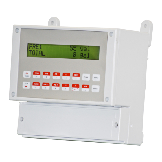
Single key direct access to measurements and display scrolling is supported. The versatility of the LDB-ST1LE permits a wide measure of versatility within the instrument package. The various hardware inputs and outputs can be “soft” assigned to meet a variety of common application needs. -
Page 6: Specifications
LDB-ST1LE Batcher 1.3 Specifications: Power Input The factory equipped power option is internally fused. An internal line to line filter capacitor is provided for Specifications: added transient suppression. Environmental Order Option 1: 110VAC: 85 to 127 Vrms, 50/60 Hz Indoor Use... - Page 7 LDB-ST1LE Batcher Excitation Voltage Analog Output The analog output is menu assignable to correspond 110/220 VAC Powered Units to the Rate or Total. Menu Selectable: 5, 12 or 24 VDC @ 100mA Type: Isolated Current Sourcing 24 VDC Powered Units...
- Page 8 LDB-ST1LE Batcher Operating Mode Setup Mode The Flow Computer can be thought of as making The setup mode is password protected by means a measurement of flow and then performing of a numeric lock out code established by the user.
- Page 9 Transaction Printing Data Logging An external modem is intentionally being used with Remote Metering by Modem (optional) the LDB-ST1LE . This permits use with the variety Computer Communication Link of modem standards worldwide while avoiding Configuration by Computer the specialized approvals required for equipment...
-
Page 10: Installation
LDB-ST1LE Batcher 2. Installation 2.1 General Mounting Hints: The LDB-ST1LE Batcher should be located in an area with a clean, dry atmosphere which is relatively free of shock and vibration. 2.2 Mounting Diagrams: 8.39” (235mm) M20 (5 places) 1.10” (28mm) 1.06”... -
Page 11: Applications
LDB-ST1LE Batcher 3. Applications 3.1 Liquid Volume Measurements: A flowmeter measures the actual volume in a liquid line. Calculations: • For Flowmeters with Pulse Outputs, Volume flow is calculated using the flowmeter frequency output and the user entered K-Factor or Linearization Table. -
Page 12: Batching
LDB-ST1LE Batcher 3.2 Batching Measurements: A flowmeter measures the actual volume in a liquid line. Calculations: • For Flowmeters with Pulse Outputs, Volume flow is calculated using the flowmeter frequency output and the user entered K-Factor or Linearization Table. Output Results: •... -
Page 13: Terminal Designations
LDB-ST1LE Batcher 4.0 Terminal Designations 1 2 3 4 5 6 7 8 9 10 11 12 13 14 15 16 17 18 19 20 21 22 1 2 3 4 5 6 23 24 TB-1 TB-2 TB-1 TB-2 COMMUNICATION... -
Page 14: Typical Batcher Wiring
LDB-ST1LE Batcher 4 WIRING 4.1 Typical Batcher Wiring: (+) V DC OUTPUT FLOW Signal PULSE IN 1 PULSE IN 2 Common COMMON NOT USED FLOW METER NOT USED with Pre Amp NOT USED NOT USED Stop Start CNTR IN 1... -
Page 15: Unit Operation
LDB-ST1LE Batcher 5. UNIT OPERATION 5.1 Front Panel Operation Concept for Run Mode The LDB-ST1LE is fully programmable through the front panel. Please review the following usage sum- TOTAL RATE PRE 1 CLEAR MENU mary before attempting to use the instrument. -
Page 16: General Operation
LDB-ST1LE Batcher 5.2 General Operation The unit can display: Rate, Total, Grand Total, Presets and Time of Day. The unit can be programmed to perform Ratemeter/Totalizer or Batching functions. 5.3 Ratemeter/Totalizer Operation The Ratemeter/Totalizer mode is used primarily to monitor flowrate and accumulated total. The relays can be used to trigger on flow rate, total, or alarms. -
Page 17: Rs-232 Serial Port Operation In Rate/Total Mode
IBM compatible PC's. The user reads and writes information from/to the RS-485 using the Modbus RTU commands. The LDB-ST1LE then responds to these information and command requests. Process variables and totalizers are read in register pairs in floating point format. Time and date are read as a series of integer register values. -
Page 18: Batcher Operation
LDB-ST1LE Batcher 5.4 Batcher Operation The Batcher mode is used primarily to control batches. The main difference between the Batch mode and Rate/Total mode is the relay operation. The Batch mode allows the operator to "START" the unit via the front panel or remote input. -
Page 19: Password Protection For Batcher Mode
LDB-ST1LE Batcher START, RESET/START and STOP, STOP/RESET When configuring the control inputs, Control Input1 can be set for START or RESET/START. When set for START, the unit will start batching when a signal is applied to Control Input 1 or the front panel Start key is pressed. -
Page 20: Rs-232 Serial Port Operation In Batcher Mode
LDB-ST1LE Batcher 5.4.6 RS-232 Serial Port Operation in Batcher mode The RS-232 serial port can be used for programming (using the Setup Disk) or for communicating to printers and computers in the Operating Mode (Run Mode). PC Communications: The Setup Disk also allows the user to query the unit for operating status such as Flow Rate, Flow Total, Presets, etc. -
Page 21: Programming
LDB-ST1LE Batcher 6. PROGRAMMING 6.1 Front Panel Operation Concept for Program Mode The LDB-ST1LE is fully programmable through the front panel. Please review the following usage summary before attempting to use the instrument. TOTAL RATE PRE 1 CLEAR MENU START... -
Page 22: Ez Setup
LDB-ST1LE Batcher 6.2 EZ Setup The EZ Setup routine is a quick and easy way to configure the unit for the most commonly used instrument functions. This setup assumes that you are measuring Volumetric Flow using a high level, DC Pulsing flow sensor. Entering the EZ Setup mode automatically sets many features. This may cause any previously programmed information to be lost or reset. -
Page 23: Setup Menus
LDB-ST1LE Batcher 6.3 Setup Menus Display Notes Sub-menus 6.3.1 Select Setup to enter the instrument setup routine. SELECT OPERATE STATE Top Level Setup Menu Setup Test 6.3.2 Refer to Page 17 for Details. STOP SELECT EZ SETUP START Sub-menu Groups... -
Page 24: Setup Sub-Menus
LDB-ST1LE Batcher 6.4 Setup Sub-Menus Sub-menus Display Notes 6.4.1 Refer to page 17 for EZ Setup routine. SELECT EZ SETUP SELECT EZ SETUP Press the DOWN (stop) key to advance to Instrument STOP Type. Press the UP (start) key to advance to START Administrative Setup. - Page 25 LDB-ST1LE Batcher Sub-menus Notes 6.4.2 Enter the maximum allowable Batch Preset. The operator MAXIMUM BATCH PRESET will not be able to enter a batch preset larger than this INSTRUMENT TYPE 1000.0 gal value. (continued) STOP START STOP START Select ON to set the unit to operate using a Batch See Section 5.4, see also...
-
Page 26: Setup Indicators (Total)
LDB-ST1LE Batcher Sub-menus Display Notes 6.4.3 Press ENTER to begin setup of the Indicators SETUP INDICATORS SETUP INDICATORS (Total) Press ENTER when Total is flashing to configure the SETUP INDICATORS Totalizer Indicators Total Rate Enter the desired Total Descriptor text... -
Page 27: Setup Flow Input (Pulse - Cha & Cha=Chb)
LDB-ST1LE Batcher Sub-menus Display Notes 6.4.5 Press ENTER to begin setup of Flow Input. SETUP FLOW INPUT SETUP FLOW INPUT (Pulse - chA & Select the desired Excitation Voltage for your flow EXCITATION VOLTAGE chA=chB) sensor. Caution: Improper selection may cause damage... -
Page 28: Setup Flow Input (Pulse - Quadrature, Qx1 Or Qx2)
LDB-ST1LE Batcher Sub-menus Display Notes Press ENTER to begin setup of Flow Input. 6.4.6 SETUP FLOW INPUT SETUP FLOW INPUT (Pulse - Quadrature, Select the desired Excitation Voltage. EXCITATION VOLTAGE Qx1 or Qx2) Press ENTER when Pulse is flashing to configure the FLOW INPUT TYPE flow input for Pulse signals. -
Page 29: Setup Pulse Output
LDB-ST1LE Batcher Sub-menus Display Notes 6.4.7 Press ENTER at this prompt to setup the Pulse Output. SETUP PULSE OUTPUT SETUP PULSE OUTPUT Select the desired Pulse Output Usage. PULSE OUTPUT USAGE Volume Select the desired Pulse Width for the Pulse Output. -
Page 30: Setup Relays
LDB-ST1LE Batcher Sub-menus Display Notes 6.4.9 Select the desired Relay for setup. SETUP RELAYS (Relays 3 & 4 Optional, menus will always appear even if SETUP RELAYS Rly1 Rly2 Rly3 Rly4 option not installed) (Relay 1 & Relay 2) If Relay 1 or Relay 2 Selected,... - Page 31 LDB-ST1LE Batcher Sub-menus Display Notes 6.4.9 (Continued) Select the desired Relay for setup. SETUP RELAYS (Relays 3 & 4 Optional) SETUP RELAYS Rly3 Rly4 Rly1 Rly2 (Relay 3 & Relay 4) If Instrument Type is set for BATCHER, RELAY 3 USAGE Choose Rate, Total, Alrm, Ovr or NA.
-
Page 32: Setup Control Inputs (Rate/Total)
LDB-ST1LE Batcher Sub-menus Display Notes 6.4.10 Press Enter to begin setup of the Control Inputs. SETUP CONTROL INPUTS SETUP CONTROL INPUTS (RATE/TOTAL) Select the desired Control Input for setup. SETUP CONTROL INPUTS Input1 Input2 Input3 If Control Input 1 Selected, CONTROL INPUT1 USAGE Select Inhibit Total or NA (Not Assigned). -
Page 33: Setup Realtime Clock (Time)
LDB-ST1LE Batcher Sub-menus Display Notes 6.4.12 Press Enter to begin setup of the Realtime Clock. SETUP REALTIME CLOCK SETUP REALTIME CLOCK (Time) Select Time to set the time. SETUP REALTIME CLOCK Time Date Select 24Hr or 12Hr clock CLOCK TYPE... -
Page 34: Serial Usage
NUMBER OF REDIALS out time if busy or no answer. (error/alarm tries until connected) Select "Yes" to perform hang-up if there is inactivity for HANGUP IF 2MIN INACT more than 2 minutes for calls initiated by the LDB-ST1LE. Advance To SETUP DATALOG/PRINT... - Page 35 LDB-ST1LE Batcher Sub-menus Display Notes 6.4.15 Press Enter to setup the Datalog/Print information. SETUP DATALOG/PRINT SETUP DATALOG/PRINT (Configure) Select Config to configure the Datalog/Print information. SETUP DATALOG/PRINT Config Select_list Select the type of Output Format. OUTPUT FORMAT Printer Term Dbase Enter the desired Page Length.
-
Page 36: Set Datalog/Print (Configure)
LDB-ST1LE Batcher Sub-menus Display Notes 6.4.16 Press enter to begin Setup Datalog/Print routine. SET DATALOG/PRINT SETUP DATALOG/PRINT (Select_list) Press enter when Select_list is selected to setup print list. SET DATALOG/PRINT Select_list Config PRINT LIST ITEMS TOTAL Use Up and Down arrow keys to view list status. -
Page 37: Setup Network Card
LDB-ST1LE Batcher Sub-menus Display Notes 6.4.18 Press Enter to setup Network Card. SETUP NETWORK CARD SETUP NETWORK CARD (optional) Select desired Network Protocol. (only Modbus RTU is SELECT NETW PROTOCOL supported) NETWORK DEVICE ID Enter the device address on network (00-247). -
Page 38: Principle Of Operation
LDB-ST1LE Batcher 7. Principals Of Operation 7.1 General: The LDB-ST1LE Batcher uses several internal calculations to compute the input frequency based on specific data input. Several computations are performed to yield flow or linearized flow. 7.2 Flow Equations: Uncompensated Flow Computation: Pulse Input;... -
Page 39: Linearization Table
LDB-ST1LE Batcher 7.3 Linearization Table 7.3.1 Linearization Table General Information The Linearization Table is used when the flow input device gives a nonlinear input signal. The unit uses up to 16 different points, as entered by the operator, to form a curve for linearizing the input signal. -
Page 40: Test, Service And Maintenance
LDB-ST1LE Batcher 8. Test, Service and Maintenance 8.1 Test Menus Sub-menus Display Notes 8.1.1 Select Test to enter the instrument test & calibration routine. TOP LEVEL SELECT OPERATE STATE NOTE: Supervisor (Service) password required to gain TEST MENUS Test Setup access to this mode. -
Page 41: Test Sub-Menus
LDB-ST1LE Batcher 8.2 Test Sub-Menus Sub-menus Display Notes 8.2.1 Press Enter to view the audit trail information. Audit Trail Audit Trail Sub-menu Group The configuration audit trail format: Config_Audit nnnnn nnnnn= number of critical menu changes, hh:mm:ss mm/dd/yy hh:mm:ss; mm/dd/yy = time and date of last change. -
Page 42: Keypad Test
LDB-ST1LE Batcher Sub-menus Display Notes 8.2.4 Press Enter to enter keypad test. Keypad test Keypad test Sub-menu Group Press the various keys and the display will show the key Keypad test that was pressed. Press Menu to exit the test. -
Page 43: Pulse Input Test
LDB-ST1LE Batcher Sub-menus Display Notes 8.2.8 Press Enter key to test the pulse input. Pulse input test Pulse input test Sub-menu Group 2.5V Use the Up/Down arrow keys to select the appropriate Pulse input test STOP 10mV START trigger level. -
Page 44: Excitation Out Test
LDB-ST1LE Batcher 8.2.11 Press Enter key to test the pulse output. Pulse out test Pulse out test To simulate a frequency on the pulse output: Connect a Sub-menu Group frequency counter to (+)TB1-13, (-)TB1-14. Press the key under the desired frequency Pulse out test setting to move the asterisk (*). -
Page 45: Internal Fuse Replacement
LDB-ST1LE Batcher 8.3 Internal Fuse Replacement Instructions: 1. Make sure you follow proper E.S.D. Precautions. All persons performing this replacement must follow proper grounding procedures. 2. Turn the power to the unit off. 3. Remove the four machine screws (see fig. 1) which hold the front panel to rear of case 4. -
Page 46: Rs-232 Serial Port
LDB-ST1LE Batcher 9. RS-232 Serial Port 9.1 RS-232 Port Description: The LDB-ST1LE has a general purpose RS-232 Port which may be used for any one of the following purposes: Transaction Printing Data Logging Remote Metering by Modem (optional) Computer Communication Link... -
Page 47: Rs-485 Serial Port
LDB-ST1LE Batcher 10. RS-485 Serial Port (optional) 10.1 RS-485 Port Description: The LDB-ST1LE has a an optional general purpose RS-485 Port which may be used for any one of the following purposes: Accessing Process Parameters Rate, Temperatures, Density, Setpoints, Month, Day, Year, Hour, Minutes, Seconds, etc. -
Page 48: Flow Computer Setup Software
Sample applications are stored in disk files. The setup program calls these Templates. You can store the setup from the program’s memory to either the LDB-ST1LE (Downloading the file) or to a disk file (Saving the file) for later usage. Similarly you can load the setup in program memory from either a disk file (Opening a file) or from the LDB-ST1LE unit (Uploading a file). -
Page 49: File Tab
3. Print the current template through the PC's printer using Print Setup option. 11.6 Setup Tab The Setup tab is where majority of the LDB-ST1LE instrument setup modifications are done. The Setup tab is divided into five sections. System Section:... -
Page 50: View Tab
If communication errors occur while reading data from the LDB-ST1LE device, the word ‘Error’ will appear in place of the actual value. If the connection to the LDB-ST1LE is lost, the viewer will time out with a message saying the device is not responding. -
Page 51: Glossary Of Terms
Alarms will reassert themselves if alarm conditions are still present. Analog Output The analog signal (4-20mA) that is generated by the LDB-ST1LE . It can correspond to the Rate or Total. This output is used primarily for transmission of process information to remote systems. - Page 52 LDB-ST1LE Batcher Flow Alarm A visual indication that the volumetric flowrate is above or below the flow alarm setpoint specified by the user. Flow Signal Timeout The Flow Signal Timeout allows the user to enter a timeout of 0 to 99 seconds. If a batch is “Filling” and zero flow persists for more than the user entered time then the batch will be aborted. This prevents over flows due to faulty flow sensors and/or wiring. Flow Equation A flow control expression or algorithm describing a mathematical equation to be solved by a flow computer in the desired application. Follow Alarm Alarm relays which are non latching and whose output state is based solely on the comparison of the current process value, the alarm setpoint (trip point) and hysteresis.
- Page 53 . Pulse Output The pulse output of the LDB-ST1LE is available for remote accumulation of the total or sent to peripheral devices, such as a PLC. The output can be scaled using the Pulse Output Scaling Constant.
- Page 54 LDB-ST1LE Batcher Quick Update % This feature is used to disable the rate averaging filter when a significant change in the flow rate occurs. The user can enter the percent of change needed to be detected to disable the averaging feature. This is especially useful during start-up and shutdown of flow. Rate Averaging Filter The rate averaging filter is used to stabilize fluctuating rate displays. Higher settings provide more averaging for a more stable display. Derived from the equation: ((OLD DATA x "Avg. Filter") + NEW DATA) ("Avg. Filter" + 1) Ratemeter Any device used to display the speed of a process. The ratemeter in the LDB-ST1LE displays flow rate.
-
Page 55: Diagnosis And Troubleshooting
LDB-ST1LE Batcher 13. Diagnosis and Troubleshooting 13.1 Response of LDB-ST1LE on Error or Alarm: Error and warning indications which occur during operation are indicated in the RUN mode alternately with the measured values. The LDB-LDB- ST1LE Batcher has three types of error:... -
Page 56: Diagnosis Flow Chart And Troubleshooting
LDB-ST1LE Batcher 13.2 Diagnosis Flow Chart and Troubleshooting All instruments undergo various stages of quality control during produc- tion. The last of these stages is a complete calibration carried out on state-of-the-art calibration rigs. A summary of possible causes is given below to help you identify faults. -
Page 57: Error & Warning Messages
The setup expects modem baud rate, parity, etc. usage and a modem is not • Check modem responding. connection and cycle power to LDB-ST1LE • Replace modem SOFTWARE ERROR RESET Software error • Report error to factory EXTENDED PFI LOCKUP Unit was operated with an input •... -
Page 58: Order Code And Warranty
LDB-ST1LE Batcher Ordering Information Example LDB ST1LE L Series: Large Display Batcher WARRANTY Function ST1= Supertrol-1 This product is warranted against ST1LE= Supertrol-1LE ES747= ES747 defects in materials and workman- ship for a period of two (2) years from Display Type: L= LCD the date of shipment to Buyer. - Page 59 LDB-ST1LE Batcher Appendix A - Setup Menus...
Need help?
Do you have a question about the LDB-ST1LE and is the answer not in the manual?
Questions and answers