Table of Contents
Advertisement
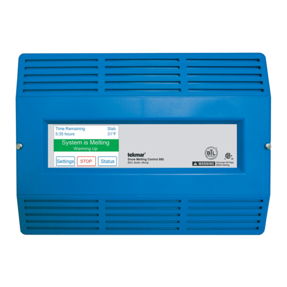
Installation & Operation Manual
Snow Melting Control 680
Introduction
The Snow Melting Control 680 is designed to operate electric or hydronic equipment to melt snow or ice from any surface
including driveways, walkways, business entrances, parking ramps, loading docks, hospital entrances, helipads and car
wash bays. It communicates with Building Automation Systems using BACnet
monitoring and adjustment capability. The 680 uses a tekmar Snow/Ice Sensor 090 or a Snow Sensor 095 to automatically
detect snow or ice on the snow melting slab. Up to two snow/ice sensors can be installed, thereby increasing detection area
and providing backup redundancy in the case of sensor failure. Upon detection of snow or ice, the 680 operates electric
heating cable, a single hydronic condensing or non-condensing boiler, or a steam valve to provide heat to the snow melt
load. The 680 provides boiler return protection by operating a mixing valve or variable speed injection mixing. Monitoring
of energy consumption is possible when it is connected to an optional flow sensor.
Features
• BACnet or Modbus communication
• Automatic snow/ice detection
• Supports both in-slab and retrofit aerial sensors
• Tandem snow/ice detection
• Energy monitoring
• Idling
or Modbus
®
• Storm
• EconoMelt
• Warm weather shut down
• Cold weather cut off
• Slab protection
• Exercising
1 of 48
Snow Melting Replaces: 10/15
for alert notification, remote
®
BACnet is a registered trademark of ASHRAE. ASHRAE
does not endorse, approve or test products for
compliance with ASHRAE standards. Compliance of
listed products to the requirements of ASHRAE Standard
135 is the responsibility of BACnet International (BI).
BTL is a registered trademark of BI.
© 2016 680_D - 05/16
680_D
05/16
Advertisement
Table of Contents

Related Manuals for Tekmar 680

Summary of Contents for Tekmar 680
- Page 1 Installation & Operation Manual 680_D Snow Melting Control 680 05/16 Snow Melting Replaces: 10/15 Introduction The Snow Melting Control 680 is designed to operate electric or hydronic equipment to melt snow or ice from any surface including driveways, walkways, business entrances, parking ramps, loading docks, hospital entrances, helipads and car wash bays. It communicates with Building Automation Systems using BACnet or Modbus for alert notification, remote ® ® monitoring and adjustment capability. The 680 uses a tekmar Snow/Ice Sensor 090 or a Snow Sensor 095 to automatically detect snow or ice on the snow melting slab. Up to two snow/ice sensors can be installed, thereby increasing detection area and providing backup redundancy in the case of sensor failure. Upon detection of snow or ice, the 680 operates electric heating cable, a single hydronic condensing or non-condensing boiler, or a steam valve to provide heat to the snow melt load. The 680 provides boiler return protection by operating a mixing valve or variable speed injection mixing. Monitoring of energy consumption is possible when it is connected to an optional flow sensor. Features • Storm • BACnet or Modbus communication • EconoMelt • Automatic snow/ice detection • Warm weather shut down • Supports both in-slab and retrofit aerial sensors • Cold weather cut off...
-
Page 2: Table Of Contents
Table of Contents Important Safety Information ..........3 Sequence of Operation ........... 35 Snow Melting Overview ..........35 Installation .................4 Melt Operation .............. 35 Preparation ..............4 Melt – Automatic Start and Stop ........35 Packaging Contents ............4 Melt – EconoMelt ............36 Physical Dimensions ............. 4 Additional Melting Time ..........36 Installation Location ............4 Melt – Automatic Start and Timed Stop ....... 36 Installing the Enclosure ..........5 Tandem Snow/Ice Detection ........37 Servicing the Control ............. 5 Melt – Manual Start and Timed Stop ...... -
Page 3: Important Safety Information
Important Safety Information It is your responsibility to ensure that this control is safely installed according to all applicable codes and standards. tekmar is not responsible for damages resulting from improper installation and/or maintenance. This is a safety-alert symbol. The safety alert symbol is shown alone or used with a signal word (DANGER, WARNING, or CAUTION), a pictorial and/or a safety message to identify hazards. When you see this symbol alone or with a signal word on your equipment or in this manual, be alert to the potential for death or serious personal injury. This pictorial alerts you to electricity, electrocution, and shock hazards. This symbol identifies hazards which, if not avoided, could result in death or serious injury. This symbol identifies hazards which, if not avoided, could result in minor or moderate injury. This symbol identifies practices, actions, or failure to act which could result in property damage or damage to the equipment. Read manual and all product labels BEFORE using the equipment. Do not use unless you know the safe and proper operation of this equipment. Keep this manual available for easy access by all users. Replacement manuals are available at tekmarControls.com • It is the installer’s responsibility to ensure that this control is safely installed according to all applicable codes and standards. • Improper installation and operation of this control could result in damage to the equipment and possibly even personal injury or death. • This control is not intended for use as a primary limit control. Other controls that are intended and certified as safety limits must be placed into the control circuit. Do not attempt to service the control. There are no user serviceable parts inside the control. Attempting to service the control voids the warranty. Radio Frequency Interference The installer must ensure that this control and its wiring are the interference by re-orientating or relocating the receiving isolated and/or shielded from strong sources of electromagnetic antenna, relocating the receiver with respect to this control, noise. Conversely, this Class B digital apparatus complies and/or connecting the control to a different circuit from that with Part 15 of the FCC Rules and meets all requirements of to which the receiver is connected. the Canadian Interference-Causing Equipment Regulations. -
Page 4: Installation
230 V (ac), 2.4 A Boiler Pump Relay: 230 V (ac), 5 A, 1/3 hp Floating Action Mixing Output: 230 V (ac), 5 A Snow Melting Control 680 Signal wiring must be Disconnect All Power BAS, Boiler & Mixing rated at least 300 V... -
Page 5: Installing The Enclosure
Installing the Enclosure • Install the control enclosure to a wall or to an electrical box. Custom Panel • Three wiring chamber dividers are included. The dividers or Electrical Box provide a barrier to keep low voltage wiring separated from line voltage wiring. • If the dividers are not used, then low voltage circuits must use wire rated at least 300 V. Wall or Panel Door Servicing the Control Signal wiring must be Disconnect All Power rated at least 300 V Before Opening Designed and assembled in Canada Step 1 Injection... -
Page 6: Rough-In Wiring
Rough-In Wiring To prevent the risk of personal injury and/or death, make sure power is not applied to the control until it is fully installed and ready for final testing. All work must be done with power to the circuit being worked on turned off. Please be aware local codes may require this control to be installed or connected by an electrician. • Install the supplied wiring compartment barriers by sliding them into the grooves provided to isolate the low and line- voltage wiring. • Strip all wiring to a length of 3/8 in. or 10 mm for all terminals. • A circuit breaker or power disconnect that provides power to the control should be located nearby and clearly labeled. • Refer to the current and voltage ratings at the back of this manual before connecting devices to this control. Low-Voltage Wiring - - - - --------------------------------------------------------------------------------- Pull two conductor 18 AWG LVT cable, up to 500 feet Pull three conductor 18 AWG LVT cable, up to 500 feet (150 m) long, for the following equipment: (150 m) long, for the following equipment: • Outdoor temperature sensor... -
Page 7: Sensor Wiring
Sensor Wiring Wiring the Analog Mixing Output ------------------- ---------------------------------------------------- The control can operate a mixing valve by providing a 0-10 V (dc) or a 4-20 mA signal to the valve actuating motor. • If applicable, connect the mixing actuator positive (+) to terminal 1. • If applicable, connect the mixing actuator negative (-) to terminal 2. − 0-10V / 4-20mA Analog Mixing Wiring the Flow Sensor - -------------------------------------------------------------------------------- An analog flow sensor can be connected to the control to provide flow and energy monitoring. The control supports a 4-20 mA style sensor. Examples of compatible aftermarket flow sensors include: • Kele SDI series • Kele 200 series with 310 transmitter • Kele 2200 series • Kele 3100 series • Omega FV100 series Out In • Omega FV-500C series Flow • Omega FTD-40 series... - Page 8 Wiring the Outdoor Sensor ----------------------------------------------------------------------------- • Connect 18 AWG or similar wire to the two terminals provided Wires from in the enclosure and run the wires from the outdoor sensor outdoor sensor to the control. Do not run the wires parallel to telephone or and sensor power cables. If the sensor wires are located in an area common with strong sources of electromagnetic interference (EMI), terminals on shielded cable or twisted pair should be used or the wires tekmar control can be run in a grounded metal conduit. If using shielded cable, the shield wire should be connected to the Com or Com Sen terminal on the control and not to earth ground. • Follow the sensor testing instructions in this manual and connect the wires to the control. • Replace the front cover of the sensor enclosure. Slide cover back over base Mounting the Boiler and System Sensors -------------------------------------------------------------- The Universal Sensor 082 is designed to mount on a pipe or in a temperature immersion well. The sensor should be placed downstream of a pump or after an elbow or similar fitting. This is especially important if large-diameter pipes are used as the thermal stratification within the pipe can result in erroneous sensor readings. Proper sensor location requires that the fluid is thoroughly...
- Page 9 Immersion Well Retaining If a Universal Sensor is mounted onto 1" (25 mm) diameter L type copper pipe, Clip there is approximately an 8 second delay between a sudden change in water Universal temperature and the time the sensor measures the temperature change. This Sensor delay increases considerably when mild steel (black iron) pipe is used. In general, it is recommended that a temperature well be used for steel pipe of diameter greater than 1-1/4" (32 mm). Temperature wells are also recommended when large diameter pipes are used and fluid stratification is present. Conduit Connection Sensor Well The Universal Sensor and Universal Sensor Enclosure 080 (sold separately) are specifically designed to mount onto a 3/8" (10 mm) ID temperature well that is supplied with an end groove. To install the well, plumb a tee into the pipe and fix the well into the tee. The 080 enclosure has a 7/8" (22 mm) back knockout that Bottom of must be removed and fitted over the temperature well. The universal sensor is Enclosure 080 then inserted into the well and the retaining clip supplied with the enclosure is snapped onto the well end groove. If the well has a threaded end, the installer must supply a standard threaded conduit retaining ring. The two wires from the sensor are connected to the terminal block provided in the enclosure. The other side of the terminal block is used to connect wires from the control. Universal Cable Tie Sensor Mounting the Boiler Supply Sensor -------------------------------------------------------------------- The boiler supply sensor is used when operating a boiler. • If applicable, connect the boiler supply sensor to terminals 8 and 9. Boil Boil No Power Wiring the Boiler Return...
-
Page 10: Communication Wiring
RS 485 • Connect the A (-) terminal on the BAS network to the RS-485 A (-) terminal 17. • Connect the ground (G) terminal on the BAS network to the Gnd terminal 18. BACnet IP Communication ----------------------------------------------------------------------------- A Building Automation System (BAS) can be connected to the control for remote monitoring and adjustment capability. BACnet IP communications use an ethernet CAT-5E or CAT-6 cable. The maximum recommended cable BACnet length for CAT-5E is 150 feet (45 m) and 300 feet (90 m) for CAT-6. Snow Melting Network Control 680 • Connect the Ethernet RJ45 plug on the BACnet IP network to the RJ45 ethernet RJ45 jack on the 680. Snow/Ice Sensor - - - - - - --------------------------------------------------------------------------------- Up to two Snow/Ice Sensor 090 or 094 can be connected to the control. The 090 has a 65' (20 m) cable and the 094 has a 208' (63 m) cable. The cable may be extended to a total length of 500' (150 m) using 18 AWG cable. Any junction boxes must kept dry. If the Snow/Ice Sensor 1 input is used: • Connect the brown wire to terminal 19. -
Page 11: Control Wiring
Snow Sensor ---- - - - - - ---------------------------------------------------------------------------------- Up to two Snow Sensor 095s can be connected to the control. If the Snow Sensor 1 input is used: • Connect the black wire to terminal 20. • Connect the blue wire to terminal 21. Snow Snow Sensor Sensor • Connect the yellow wire to terminal 22. • Connect the red wire to terminal 23. If the Snow Sensor 2 input is used: • Connect the black wire to terminal 20. Brn/ Blk/ Brn/ Blk/ • Connect the blue wire to terminal 25. Slab Slab • Connect the yellow wire to terminal 27. • Connect the red wire to terminal 28. Snow/Ice Sensor 1 Snow/Ice Sensor 2 Slab Sensor - - - - - - - - - -----------------------------------------------------------------------------------... - Page 12 The control provides either a 4-20 mA or a 0-10 V (dc) output to the boiler. Polarity must be 33 34 observed. Boiler 1 • Connect the Mod + terminal from the boiler to terminal 33. Stage 1 Stage 2 • Connect the Mod - terminal from the boiler to terminal 34. • Some modulating boilers require an enable to start firing the boiler. Connect the boiler enable to the stage 1 terminals 35 and 36. Enable The 4 to 20 mA output can be converted to a 0 - 135 Ω output The 4 to 20 mA output can be converted to a 0 - 135 Ω output for a Modutrol IV™ gas valve actuating motor using a 0 - 135 Ω for a V9055™ gas valve actuating motor using a 0 - 135 Ω tekmar Converter 005 (sold separately). tekmar Converter 005 (sold separately). Modutrol IV™ Modutrol IV V9055 Modutrol IV V9055 V9055™ 0 - 135 Ω 0 - 135 Ω Actuating Actuating Motor Motor tekmar tekmar...
- Page 13 Wiring the Boiler Pump - -------------------------------------------------------------------------------- A boiler pump requiring up to can be switched through 230 V (ac), 5A, 1/3 hp terminals 39 and 40. For simplicity in wiring and troubleshooting, a separate Boiler breaker for each pump is recommended. Pump • Connect the power source line wire (L) to terminal 39. • Connect a wire from terminal 40 to the pump L. • Connect a wire from the pump N back to the power source neutral. • Connect the ground wire (G) to one of the ground screws provided in the wiring chamber. Ground Wiring the Floating Action Mixing Output - -------------------------------------------------------------- The control provides a floating action signal to operate a floating action actuator. The floating action mixing output uses dry relay contacts that can switch either 24, 120, or 230 Floating V (ac). When using 24 V (ac), a Transformer 009 is required to power the actuator. The Action Mixing Opn Cls Pwr actuator terminals are typically labeled for clockwise and counterclockwise rotation. The control's open and close terminals are wired to the actuator depending on the direction the valve rotates to open and close respectively.
-
Page 14: Testing The Sensor Wiring
Testing the Sensor Wiring A good quality test meter capable of measuring up to 5,000 kΩ the temperature measured by the sensor. The sensor and (1 kΩ = 1000 Ω) is required to measure the sensor resistance. thermometer readings should be close. If the test meter reads In addition, the actual temperature must be measured with a very high resistance, there may be a broken wire, a poor either a high-quality digital thermometer, or if a thermometer wiring connection or a defective sensor. If the resistance is is not available, a second sensor can be placed alongside very low, the wiring may be shorted, there may be moisture the one to be tested and the readings compared. in the sensor or the sensor may be defective. To test for a defective sensor, measure the resistance directly at the First, measure the temperature using the thermometer and sensor location. then measure the resistance of the sensor at the control. The wires from the sensor must not be connected to the control Do not apply voltage to a sensor at any time as damage while the test is performed. Using the chart below, estimate to the sensor may result. Temperature Resistance Temperature Resistance... -
Page 15: Manual Override - Maximum Heat
For the Mix System Output – Analog Mixing Exiting the Hand Manual Override --------------- • Use an electrical meter set to measure V (dc) or mA. • Exit the Manual Override by selecting Auto. • Set the Mix System Output to 100%. • Install the front cover. • The voltage between the + and – wiring terminals should be 10 V (dc) or 20 mA. • Set the Mix System Output to 0%. • The voltage between the + and – wiring terminals should be 0 V (dc) or 4 mA. For the Mix System Output – Variable Speed Injection Mixing • Use an electrical meter set to measure V (ac). -
Page 16: Switch Settings
230 V (ac), 2.4 A Boiler Pump Relay: 230 V (ac), 5 A, 1/3 hp Floating Action Mixing Output: 230 V (ac), 5 A Snow Melting Control 680 Signal wiring must be Disconnect All Power BAS, Boiler & Mixing rated at least 300 V... -
Page 17: User Interface
User Interface Home Screen Slab and outdoor Remaining melting conditions information run time System operation information Touchscreen buttons System Operation SYSTEM IS MELTING • Warming Up The slab has not yet reached the slab target temperature. SYSTEM IS OFF • Warm Weather Shut Down The slab and outdoor temperature have exceeded the WWSD setting. • Cold Weather Cut Off The outdoor temperature has fallen below the CWCO setting. System will resume melting once outdoor temperature increases above • Melt Pending the CWCO setting. SYSTEM IS IDLING STORM PREDICTED SYSTEM IN OVERRIDE • Hand The control is in hand manual override. -
Page 18: Symbols
Symbols WARNING SYMBOL The control has a error message. Press the warning symbol to determine the error code and information on how to take corrective action. Refer to the Troubleshooting section for a list of error codes. Help Screen The display includes a Help screen for each setting. The Help screen provides a description of the setting that is identical to the description found in the Installation and Operation Manual. Status Menu Navigation Step 1: Press the Status button on the Home Screen. Step 2: Press either the System or Slab button. Step 3: Press up or down buttons to scroll through the list. © 2016 680_D - 05/16 18 of 48... -
Page 19: Slab Status Screen
Slab Status Screen Description Range Access OUTDOOR – – –, User Current outdoor air temperature as measured by the outdoor sensor or provided by the BAS -67 to 149°F system. “– – –” is displayed when no outdoor sensor is available. Installer (-55.0 to 65.0°C) Conditions: Always available. SLAB TARGET – – –, -76 to The slab target calculated by the control based on outdoor temperature and the melting, Installer 149°F idling, or storm setpoints. “- - -” is displayed when no heat is required. (-60.0 to 65.0°C) Conditions: Always available. SLAB SENSOR 1 User -58 to 167°F Current slab sensor 1 temperature. (-50.0 to 75.0°C) Installer Conditions: Snow/ice sensor 1 set to In-slab or Slab sensor 1 is set to On. SENSOR 1 WATER STATUS User Current status of snow/ice sensor 1 moisture detector. DRY or WET Installer Conditions:... -
Page 20: System Status Menu (1 Of 2)
System Status Menu (1 of 2) Description Range Access BOILER TARGET – – –, User The boiler target calculated by the control based on outdoor temperature, slab temperature and the 50 to 230°F melting, idling, or storm setpoints. “- - -” is displayed when no heat is required. Installer (10.0 to 110.0°C) Conditions: Application mode is set to Boiler or Boiler+Mix. BOILER SUPPLY -31 to 266°F Installer Current boiler supply water temperature. (-35.0 to 130.0°C) Conditions: Application mode is set to Boiler or Boiler+Mix. BOILER RETURN User -31 to 266°F Current boiler return water temperature. (-35.0 to 130.0°C) Installer Conditions: Application mode is set to Boiler or Boiler+Mix. BOILER OUTPUT User Current boiler plant percent output. 0 to 100% Installer Conditions: Application mode is set to Boiler or Boiler+Mix. -
Page 21: System Status Menu (2 Of 2)
System Status Menu (2 of 2) Description Range Access SYSTEM PUMP User Current status of the system loop pump. On or Off Installer Conditions: Application mode is set to PWM Zone, Mixing or Boiler+Mix. SYSTEM FLOW RATE User 0 to 1000 GPM The system flow rate measured by the flow meter. Conditions: 1) Application mode is set to PWM Zone, Boiler, Mixing or Boiler+Mix and 2) Installer (0 to 227 m Flow sensor is set to On. SYSTEM PRESSURE User 0 to 300 psi The system pressure measured by the pressure sensor. Conditions: Application mode is set to PWM Zone, Boiler, Mixing or Boiler+Mix, and 2) a Installer (0 to 2069 kPa) Pressure Sensor is installed. ELECTRIC ENABLE RELAY User Current status of the electric snow melt enable relay. On or Off Installer Conditions: Application mode is set to Electric. -
Page 22: Settings Menu Navigation
Settings Menu Navigation Step 1: Press the Settings button on the Home Screen. Step 2: Press one of the six buttons. Step 3: Press up or down buttons to scroll through the list. Step 4: Press the highlighted setting name to change the setting value. In the BAS menu, settings using a number keypad require touching the number field and then pressing the "Clear" button before entering the number. © 2016 680_D - 05/16 22 of 48... -
Page 23: Setpoints Menu
Setpoints Menu Description Range Access 32 to 95°F MELTING SETPOINT User (0.0 to 35.0°C) Select the desired temperature of the snow melt surface when melting. Installer Default = 36°F Conditions: Always available. (2.0°C) IDLING SETPOINT OFF, 20 to 95°F Select the desired temperature of the snow melt surface when idling. Idling pre-heats the slab User (-6.5 to 35.0°C) when the slab is dry but cold and allows faster reaction time to reach the melting temperature Installer when snow is detected. Recommended for commercial use only. Default = Off Conditions: Always available. STORM SETPOINT Select the desired temperature of the snow melt surface while operating in the storm OFF, 20 to 95°F User operation. Storm operation temporarily pre-heats the slab to allow faster reaction time to (-6.5 to 35.0°C) reach the melting temperature when snow is detected. Storm operation is activated through Installer Default = Off a BACnet or Modbus command. Conditions: Always available. 0:30 to 24:00 MANUAL MELT TIME User hours Select the amount of running time when manually starting the system. -
Page 24: Setup - System Setup Menu (1 Of 2)
Setup – System Setup Menu (1 of 2) Description Range Access APPLICATION MODE The Application Mode selects the operation of the mechanical equipment. Application Mode “PWM Zone” operates a pump or zone valve to provide heat to the snow melting system. PWM Zone Mixing Application Mode “Mixing” operates a mixing valve or a variable speed injection mixing pump to Boiler heat the snow melting system. The heat source is enabled. Boiler+Mix Installer Application Mode “Boiler” operates a modulating, 1-stage or 2-stage boiler to heat the snow melting Electric system. Default = Application Mode “Boiler+Mix" operates a mixing valve or a variable speed injection mixing pump Boiler+Mix and controls the boiler temperature to heat the snow melting system. Application Mode “Electric” uses electric cables to heat the snow melting system. Conditions: Always available. SNOW/ICE SENSOR 1 None, In-slab, Select if a Snow/Ice Sensor 090 or 094 (In-slab), or a Snow Sensor 095 (Aerial) is installed Aerial Installer on the Snow/Ice Sensor 1 input. Default = In-slab Conditions: Always available. -
Page 25: Setup - System Setup Menu (2 Of 2)
Setup – System Setup Menu (2 of 2) Description Range Access PRESSURE SENSOR Off or On Select if a pressure sensor is installed. Installer Default = Off Conditions: Available when the Application Mode is not set to Electric. 50, 100, 150, 200, 250, 300 PRESSURE RANGE (345, 690, 1034, Select the maximum pressure rating of the installed pressure sensor. Installer 1379, 1724, 2069 Conditions: Available when 1) The Application Mode is not set to Electric, and 2) Pressure kPa) Sensor is set to On. Default = 50 psi (345 kPa) LOW PRESSURE WARNING Off, 5 to 25 psi Select the low pressure limit below which a warning message is generated. Installer (35 to 173 kPa) Conditions: Available when 1) The Application Mode is not set to Electric, and 2) Pressure Default = Off Sensor is set to On. -
Page 26: Setup - Boiler Setup Menu (1 Of 2)
Setup – Boiler Setup Menu (1 of 2) Description Range Access BOILER TYPE Select the type of boiler operated by the control. Mod = Modulating boiler with an adjustable firing rate using a 0-10V (dc) or 4-20 mA signal. Mod, 1 Stage, 2 1 Stage = Single one-stage on/off boiler. Stage, EMS Installer 2 Stage = Single two-stage on/off boiler. Default = Mod EMS = Modulating boiler with an adjustable target temperature using a 0-10V (dc) or 4-20 mA signal. Conditions: Application Mode is set to Boiler or Boiler+Mix. 0-10 V BOILER MODULATION TYPE Select between a 0-10 V (dc) or 4-20 mA signal to control the modulating boiler. Installer 4-20 mA Conditions: Available when 1) Application Mode is set to Boiler or Boiler+Mix, and 2) Boiler Type is set to Mod or EMS. Default: 0-10 V BOILER MIN MODULATION 0 to 50% Set the boiler minimum modulation of the boiler burner. Installer Conditions: Available when 1) Application Mode is set to Boiler or Boiler+Mix, and 2) Boiler Type Default = 0% is set to Mod or EMS. -
Page 27: Setup - Boiler Setup Menu (2 Of 2)
Setup – Boiler Setup Menu (2 of 2) Description Range Access 50 to 210°F EMS HIGH TEMPERATURE (10.0 to 99.0°C) The EMS modulating boiler target temperature that corresponds to 10 V (dc) or 20 mA. Installer Check the boiler manufacturer’s manual for the maximum EMS target temperature. Default = 210°F Conditions: Available when Boiler Type is set to EMS. (99.0°C) Setup – Mixing Setup Menu Description Range Access MIXING TYPE Select the mixing output type. Floating, Floating = Floating action mixing output to operate a mixing valve. Injection, 0-10 V, Injection = Injection mixing output to operate a wet-rotor, impedance protected pump with a current Installer less than 2.4 A. or 4-20 mA 0-10 V = Analog mixing output provides a 0-10 V (dc) signal. -
Page 28: Bas Menu (1 Of 2)
BAS Menu (1 of 2) Settings using a number keypad require touching the number field and then pressing the "Clear" button before entering the number. Description Range Access BAS TYPE Select the communication protocol used with the BAS network. None, BACnet-IP, None = No communication. The control operates in stand-alone. BACnet-MSTP, BACnet-IP = The control communicates to a BACnet-IP BAS system. Installer Modbus BACnet-MSTP = The control communicates to a BACnet-MSTP BAS system. Default = None Modbus = The control communicates to a Modbus BAS system. Conditions: Always available. -
Page 29: Bas Menu (2 Of 2)
BAS Menu (2 of 2) Description Range Access BBMD PORT 0 to 65535 Set the BACnet Broadcast Management Device (BBMD) UDP port on the BACnet Installer network. Default = 47808 Conditions: Available when BAS Type is set to BACnet-IP. BBMD TIME 30 to 65535 Set the BACnet Broadcast Management Device (BBMD) time-to-live in seconds for foreign seconds device registration on a BACnet network. Installer Default = 30 Conditions: Available when 1) BAS Type is set to BACnet-IP, and 2) Register Foreign Device is seconds set to On. 000.000.000.000 BBMD IP Set the BACnet Broadcast Management Device (BBMD) IP address on the BACnet Installer network. 255.255.255.254 Conditions: Available when 1) BAS Type is set to BACnet-IP, and 2) Register Foreign Device is Default = set to On. 127.127.127.127 MAC ADDRESS XX:XX:XX:XX: Installer This is the Media Access Control (MAC) address of this product. -
Page 30: Monitor Menu (1 Of 3)
Monitor Menu (1 of 3) Description Range Access Hydronic 0 to 999999 MELTING ENERGY thm or GJ User Records the amount of energy used by the snow melting system since the counter was last reset. Installer Conditions: Always available. Electric 0 to 999999 kWh MELTING HOURS User 0 to 999999 R ecords the number of melting hours since the counter was last reset. hours Installer Conditions: Always available. HEAT HOURS User 0 to 999999 Records the number of hours the boiler fired or the electric cable heated since the counter was last reset. hours Installer Conditions: Always available. HEAT CYCLES 0 to 999999 Records the number of cycles the boiler turned on or the electric cable heated since the Installer... -
Page 31: Monitor Menu (2 Of 3)
Monitor Menu (2 of 3) Description Range Access OUTDOOR HIGH -67 to 149°F Installer Records the highest measured outdoor air temperature since the counter was last reset. (-55.0 to 65.0°C) Conditions: Always available. OUTDOOR LOW -67 to 149°F Records the lowest measured outdoor air temperature since the counter was last reset. Installer (-55.0 to 65.0°C) Conditions: Always available. BOILER SUPPLY HIGH -31 to 266°F Records the highest measured boiler supply temperature since the counter was last Installer reset. (-35.0 to 130.0°C) Conditions: Available when Application Mode is set to Boiler or Boiler+Mix. BOILER SUPPLY LOW -31 to 266°F Records the lowest measured boiler supply temperature since the counter was last reset. Installer (-35.0 to 130.0°C) Conditions: Available when Application Mode is set to Boiler or Boiler+Mix. BOILER RETURN HIGH -31 to 266°F Installer Records the highest measured boiler return temperature since the counter was last reset. -
Page 32: Monitor Menu (3 Of 3)
Monitor Menu (3 of 3) Description Range Access FLOW RATE HIGH 0 to 1000 GPM R ecords the highest system flow rate since the counter was last reset. Installer Conditions: Available when 1) Application Mode is not set to Electric and 2) Flow Sensor is set (0 to 272 m to On. FLOW RATE LOW 0 to 1000 GPM Records the lowest system flow rate since the counter was last reset. Installer Conditions: Available when 1) Application Mode is not set to Electric and 2) Flow Sensor is set (0 to 272 m to On. RESET ALL? Installer Resets all the counters in the monitor menu at once. Conditions: Always available. © 2016 680_D - 05/16 32 of 48... -
Page 33: Toolbox Menu
Range Access ERROR CODE User See Error Code The current error code is displayed. Section Installer Conditions: Always available. ACCESS LEVEL User User or Installer Select the access level of the control. This determines which menus and items are available through the user interface. Installer Default = Installer Available when the DIP switch is set to Unlocked. Conditions: TYPE 680 Product information. Product 680 J1243B User tektra #: 107001 Last letter indicates Installer SW: J1243B software version SVN: 1054 Always available. Conditions: SCREEN BRIGHTNESS User 0 to 100% Select the screen brightness. Default = 75% Installer Always available. -
Page 34: Override Menu
Override Menu Description Range Access MANUAL OVERRIDE Manually override the normal automatic operation of the control to test the equipment or operate the system at the maximum temperature limits. Auto = Normal operation. Auto, Hand, Max User Hand = Manual override of each relay output. Heat, Test, Purge, Installer Max Heat = Operate hydronic system at maximum heat. Test = Operate electric system for 10 minutes. Purge = Hydronic system purge operates pumps to help bleed air from the system. Conditions: Always available. SYSTEM PUMP Off or On Manually turn on the system pump during the HAND Manual Override. Installer Conditions: Available when 1) Application Mode is set to PWM Zone, Boiler, Mixing or Boiler+Mix, Default = Off and 2) Manual Override is set to Hand. PRIMARY PUMP Off or On Manually turn on the primary pump during the HAND Manual Override. Installer Conditions: Available when 1) Application Mode is set to PWM Zone, Boiler, Mixing or Boiler+Mix, Default = Off and 2) Manual Override is set to Hand. BOILER PUMP Off or On Manually turn on the boiler pump during the HAND Manual Override. Installer Conditions: Available when 1) Application Mode is set to PWM Mode, Boiler or Boiler+Mix, and Default = Off 2) Manual Override is set to Hand. -
Page 35: Sequence Of Operation
Sequence of Operation Snow Melting Overview A snow melting system can offer a safe, convenient, and cost The snow melting control can operate in one of four effective way of removing snow and ice from the snow melting different ways: slab and similar surfaces. Safety is increased by activating Melt Heats the slab to melt snow or ice the snow melting system as soon as the snow falls rather Idle Pre-heats the slab just below freezing to shorten the than waiting for mechanical snow removal after snow has time required to melt snow accumulated. This eliminates slip hazards and reduces the Storm Temporarily pre-heats the slab just below freezing to risk of injury by mechanized snow melting equipment, thereby shorten the time required to melt snow reducing potential liability costs. The elimination of snow plow Off Snow melting system is off equipment and corrosive salts also reduces damage to the slab surface and to the environment. When controlled correctly, The display shows the control operation in the home screen. snow melting systems can be cost competitive compared to mechanical snow removal. Melt Operation The snow melting system operates the heating equipment using a snow/ice sensor, manually by pressing the Melt button to heat the slab from a cold start or from the idle or storm on the display, or through the BACnet or Modbus protocol. temperature to reach the melt temperature setting to melt The melt temperature setting affects calculated targets such snow or ice. Melt operation can be triggered automatically as the slab target, boiler target and mix target. -
Page 36: Melt - Economelt
Melt EconoMelt – When a Snow/Ice Sensor 090 or 094 is installed, the installer Push Melt button can choose to select to either automatically or manually start BACnet or Modbus Melt Request the snow melting system. Selecting EconoMelt to On allows snow removal using a snow plow or shovel. The remaining thin 090 and slab dry and Add Melt time elapses layer of snow or ice that mechanical snow removal methods are unable to remove can be melted using the manual start Melt Press Stop button operation. The snow melting system stops when the sensor WWSD is dry. The factory default for EconoMelt is Off. BACnet or Modbus Stop Request Enters Exits CWCO Melt CWCO Suspended Additional Melting Time A Snow/Ice Sensor 090 or 094 automatically shuts off the snow melting system when the water sensor is dry. Due to Snow Ice Sensor the construction of the slab and the layout of the heating pipe or electrical cable, there may be areas that do not melt completely. The Additional Melt Time setting in the Setpoints menu allows the installer to set addition melting time after the sensor is dry. Melt Automatic Start and Timed Stop –... -
Page 37: Tandem Snow/Ice Detection
Tandem Snow/Ice Detection The control allows any combination of two Snow/Ice sensors 090 or 094 or Snow Sensors 095 to be installed. This provides full redundancy and increases the snow detection area. Both sensors are used to detect snow or ice and if either sensor is wet the snow melting zone starts melting. The control continues to operate until both sensors are dry. This allows snow or ice detection over a wider area. In the event of a sensor failure, the control continues to operate normally, giving building maintenance staff time to troubleshoot and replace the faulty sensor if necessary. Melt Manual Start and Timed Stop – The snow melting system can be started manually in one of If a manual start has been provided and a Snow/Ice Sensor two different methods: detects water, the control changes from manual melt to automatic operation. The snow melting system will continue • Touch the Melt button on the control display. to operate until the sensor is dry and the Additional Melt • The Melt/Stop Request parameter in the BACnet or Modbus Time elapses. communication protocol. Once manually started, the snow melting system continues to operate until the time set by the Manual Melt Run Time setting in the Setpoints menu elapses. Push Melt button BACnet or Modbus Melt Request Idle Timed Manual Melt Run Time elapses Melt Push Stop button BACnet or Modbus Stop Request... -
Page 38: Idle Operation
Idle Operation When the snow melting system starts from a cold temperature, at a temperature several degrees below freezing to reduce there may be a long time delay before the slab is warm enough energy consumption. Applications may include: to melt snow. This time delay allows snow to accumulate on • Steep residential driveways the slab which is not acceptable in some commercial and • Commercial sidewalks institutional applications. To decrease the start-up time, the slab • Loading docks can be pre-heated to maintain a minimum temperature. This A Snow-Free Area Ratio of 0 is defined as a system that is known as the Idle temperature. Idling requires large energy allows snow accumulation. These systems operate the snow consumption and is generally recommended for institutional melting system from a cold start resulting in the lowest energy and/or commercial installations where safety concerns are consumption costs and the longest times to start melting snow. paramount. The display shows "System is Idling" when the In this case set the Idle to off. This is recommended for most control is in idle operation. residential applications such as: When designing a snow melting system, an engineer may • Flat residential driveways specify the amount of allowed snow accumulation as the • Patios Snow-Free Area Ratio. There are three different levels. A • Residential sidewalks Snow-Free Area Ratio of 1 is defined as a system that melts Some systems are designed for keeping a slab surface free of all snow as it falls with no allowed accumulation. This requires ice rather than free of snow. The most common applications that the Idle temperature be set just below freezing. Examples include: of these types of applications include:... -
Page 39: Slab Protection
Slab Protection In a hydronic snow melting system, the boiler or heating plant capacity may be much larger than the load of the snow tensile stresses melting zones. This can result in large temperature differentials between the supply water temperature and the slab creating large tensile stresses on the slab. Concrete is weak to tensile forces and when repeatedly exposed to tensile loads the concrete may crack. This may be prevented by selecting the Slab Protection setting in the System Setup menu to On. The control measures and limits the temperature differential between the supply water and the slab. Warm Weather Shut Down During warm weather, the slab is warm enough to naturally Manual WWSD melt snow or ice. The control has a Warm Weather Shut Down The control enters WWSD when the outdoor air temperature (WWSD) setting in the Setpoints menu that prevents the control exceeds the WWSD setting by 1°F (0.5°C) and when the from entering Melt, Idle or Storm operation in order to conserve slab temperature exceeds 34°F (1°C). The control exits energy. The control shows, "System is Off – Warm Weather WWSD when the outdoor air temperature falls 1°F (0.5°C) Shut Down" on the display when WWSD is in effect. below the WWSD setting or if the slab temperature falls below 34°F (1°C). This allows the Melting Setpoint setting Automatic (Auto) to be set higher than the WWSD. This is useful when high The control enters WWSD when both the slab temperature slab temperatures are required to melt the snow or ice. An and the outdoor temperature exceed the Melting Setpoint example of this are installations using paving bricks on top temperature setting by more than 2°F (1°C). of sand and concrete layers. -
Page 40: Application Modes
Application Modes The snow melting control can operate either an electric or • PWM Zone Pulse Width Modulation Zone Operation a hydronic snow melting system. A hydronic system can be • Boiler Boiler Operation categorized as boiler, mixing, boiler and mixing, or pulse • Mixing Mixing Operation width modulation zone operation. A dedicated boiler only • Boiler+Mix Boiler and Mixing Operation provides heat for the snow melting system. A shared boiler • Electric Electrical Operation provides heat for the snow melting system in addition to the space heating and/or a domestic hot water system. These choices affect which Application Mode is selected in the System Setup menu: Electric Operation The Application Mode should be set to Electric when operating Relay operation: an electric heating cable. The control operates the boiler stage • System pump — not used 1 relay on a 20-minute pulse width modulation cycle. The boiler • Primary pump — not used stage 1 relay in turn activates a line voltage electrical contactor • Boiler pump — not used to energize the electrical cable heater installed in the slab. -
Page 41: Boiler Operation
Boiler Operation The Application Mode should be set to Boiler when the snow EMS --------------------------------------------- melting system has a dedicated boiler or heat source and there When the boiler is required to operate, the control's boiler is no mixing device. The boiler is piped primary-secondary modulation output is adjusted to an appropriate analog signal to the snow melting loop, allowing the boiler to fire on and corresponding to the boiler target temperature and then turns off while allowing continuous flow through the snow melting on the boiler stage 1 relay. The analog signal is proportional system loop. The control calculates a Boiler Target based upon to the boiler target in a linear line defined by the EMS Signal the Slab Target, which in turn is based upon the measured Minimum, the EMS Low Temperature, and the EMS High outdoor temperature and the Melt, Idle or Storm temperature Temperature settings. setting. The boiler is fired to maintain the Boiler Target at the Boiler Supply Sensor location. The control can operate a boiler EMS HIGH in one of four different methods: modulating boiler, 1 stage, TEMP 2 stage and EMS. The Boiler Target is shown in the System 10V(dc) Status menu. Settings for the boiler operation are located in the Boiler Setup menu. 1 Stage Boiler - - - - - - - ---------------------------- The control turns the boiler stage 1 relay on or off to fire the boiler and maintain the Boiler Target temperature. The boiler supply temperature operates on a differential that is half above... -
Page 42: Mixing Operation
Mixing Operation The Application Mode should be set to Mixing when a mixing • Primary pump — operates continuously during melt, idle valve or a mixing injection pump is installed with a shared or storm boiler plant. Four mixing options are available: • Boiler pump — not used • Floating action mixing valve • Boiler stage 1 — turns on when the valve is open or the injection mixing pump is operating. • Variable-speed injection pump • Boiler stage 2 — not used • Analog mixing using 0-10 V (dc) If using Floating Action Mixing • Analog mixing using 4-20 mA The control calculates the Slab Target temperature based on • Floating action open — contact closes momentarily when the outdoor air temperature and the Melting, Idling or Storm pulsing actuator open Setpoint. The control then determines the Mix System Target • Floating action closed — contact closes momentarily when based on the Slab Target requirements. The Mix Maximum setting pulsing actuator closed limits the upper temperature of the Mix System Target. The If using Variable Speed Injection Mixing Mix System Target is shown in the System Status menu. -
Page 43: Troubleshooting
Troubleshooting It is recommended to complete all wiring to ensure trouble free operation. Should an error occur, simply follow these steps: 1. Find: If the control shows the Warning Symbol on the screen, it is indicating a problem on the system. 2. Identify: Press the Warning Symbol to view the error code. 3. Solve: Use the chart below to match the error code to the one on the control. Use the description to solve the problem. Error Messages (1 of 4) Description SETPOINTS MENU SAVE ERROR The control failed to read the Setpoints menu settings from memory and has reloaded the factory default settings. The control stops operation until all settings in the Setpoints menu are checked. To clear the error, set the access level to Installer and check all settings in the Setpoints menu. SYSTEM SETUP MENU SAVE ERROR The control failed to read the System Setup menu settings from memory and has reloaded the factory default settings. The control stops operation until all settings in the System Setup menu are checked. To clear the error, set the access level to Installer and check all settings in the System Setup menu. BOILER SETUP MENU SAVE ERROR The control failed to read the Boiler Setup menu settings from memory and has reloaded the factory default settings. The control stops operation until all settings in the Boiler Setup menu are checked. To clear the error, set the access level to Installer and check all settings in the Boiler Setup menu. MIXING SETUP MENU SAVE ERROR The control failed to read the Mixing Setup menu settings from memory and has reloaded the factory default settings. The control stops operation until all settings in the Mixing Setup menu are checked. -
Page 44: Error Messages (2 Of 4)
Error Messages (2 of 4) Description SYSTEM SUPPLY SENSOR OPEN CIRCUIT ERROR Due to an open circuit, the control is unable to read the System Supply Sensor 082 on terminals 11 and 12. The control stops operation and does not provide any heat. Check the system supply sensor wire for open circuits according to the sensor installation manual. It may be necessary to replace the system supply sensor. Once the error has been corrected, the error message automatically clears. SYSTEM SUPPLY SENSOR SHORT CIRCUIT ERROR Due to a short circuit, the control is unable to read the System Supply Sensor 082 on terminals 11 and 12. The control stops operation and does not provide any heat. Check the system supply sensor wire for short circuits according to the sensor installation manual. It may be necessary to replace the system supply sensor. Once the error has been corrected, the error message automatically clears. SYSTEM RETURN SENSOR OPEN CIRCUIT ERROR Due to an open circuit, the control is unable to read the System Return Sensor 082 on terminals 11 and 13. The control continues normal operation but does not accumulate any energy usage. Check the system return sensor wire for open circuits according to the sensor installation manual. It may be necessary to replace the system return sensor. Once the error has been corrected, the error message automatically clears. SYSTEM RETURN SENSOR SHORT CIRCUIT ERROR Due to a short circuit, the control is unable to read the System Return Sensor 082 on terminals 11 and 13. The control continues normal operation but does not accumulate any energy usage. -
Page 45: Error Messages (3 Of 4)
Error Messages (3 of 4) Description SNOW SENSOR 1 YELLOW WIRE OPEN CIRCUIT ERROR Due to an open circuit, the control is unable to read the yellow wire connected to the Snow/Ice Sensor 090 or 094, or the Snow Sensor 095 on terminals 20 and 22. The control continues normal operation if snow/ice sensor 2 is installed; otherwise, the control can no longer automatically detect snow or ice, but manual start of the snow melting system is still available. Check the snow/ice sensor or snow sensor yellow and black wires and any wire splices for open circuits according to the sensor installation manual. It may be necessary to replace the sensor. Once the error has been corrected, the error message automatically clears. SNOW SENSOR 1 BLUE WIRE OPEN CIRCUIT ERROR Due to an open circuit, the control is unable to read the blue wire connected to the Snow/Ice Sensor 090 or 094, or the Snow Sensor 095 on terminals 20 and 21. The control continues normal operation if snow/ice sensor 2 is installed; otherwise, the control can no longer automatically detect snow or ice, but manual start of the snow melting system is still available. Check the snow/ice sensor 1 or snow sensor 1 blue and black wires and any wire splices for open circuits according to the sensor installation manual. It may be necessary to replace the sensor. Once the error has been corrected, the error message automatically clears. SNOW SENSOR 1 BLUE WIRE SHORT CIRCUIT ERROR Due to a short circuit, the control is unable to read the blue wire connected to the Snow/Ice Sensor 090 or 094, or the Snow Sensor 095 on terminals 20 and 21. The control continues normal operation if snow/ice sensor 2 is installed; otherwise, the control can no longer automatically detect snow or ice, but manual start of the snow melting system is still available. -
Page 46: Error Messages (4 Of 4)
Error Messages (4 of 4) Description SLAB SENSOR 2 SHORT CIRCUIT ERROR Due to a short circuit, the control is unable to read the Slab Sensor 072 or 073 on terminals 24 and 25. The control continues normal operation if slab sensor 1 is installed; otherwise, Idling and Storm are disabled and energy saving features such as Warm Weather Shut Down (WWSD) and Cold Weather Cut Off (CWCO) are operated using the outdoor temperature only. Check the slab sensor 2 wire for short circuits according to the sensor installation manual. It may be necessary to replace the slab sensor. Once the error has been corrected, the error message automatically clears. SNOW SENSOR 2 YELLOW WIRE OPEN CIRCUIT ERROR Due to an open circuit, the control is unable to read the yellow wire connected to the Snow/Ice Sensor 090 or 094 or the Snow Sensor 095 on terminals 25 and 27. The control continues normal operation if snow/ice sensor 1 is installed; otherwise, the control can no longer automatically detect snow or ice, but manual start of the snow melting system is still available. Check the snow/ice sensor 2 or snow sensor 2 yellow and black wires and any wire splices for open circuits according to the sensor installation manual. It may be necessary to replace the sensor. Once the error has been corrected, the error message automatically clears. SNOW SENSOR 2 BLUE WIRE OPEN CIRCUIT ERROR Due to an open circuit, the control is unable to read the blue wire connected to the Snow/Ice Sensor 090 or 094 or the Snow Sensor 095 on terminals 25 and 26. The control continues normal operation if snow/ice sensor 1 is installed; otherwise, the control can no longer automatically detect snow or ice, but manual start of the snow melting system is still available. -
Page 47: Frequently Asked Questions
Frequently Asked Questions Symptom Look For... Corrective Action Touchscreen is Use electrical meter to measure 115 V (ac) voltage on input power L and N Power to control terminals. System pump Idle operation requires that the system pump operate continuously while below the Display shows Idle always on melting temperature setting. Dirt or salt on snow/ The snow/ice sensor requires regular cleaning. Avoid using road salt on the snow Blue short ice sensor melting slab. Slab is above melt Slab Target The slab is heated to the slab target. -
Page 48: Technical Data
Representative. tekmar Control Systems Ltd., A Watts Water Technologies Company. Head Office: 5100 Silver Star Road, Vernon, B.C. Canada V1B 3K4, 250-545-7749, Fax. 250-984-0815 Web Site: tekmarControls.com 48 of 48 Product design, software and literature are Copyright ©2016 by...
Need help?
Do you have a question about the 680 and is the answer not in the manual?
Questions and answers