Advertisement
Quick Links
Installa�on Overview
Read this manual carefully before installing and operating!
Detect door orientation
(Step 8-9)
Customize setting
(See Quick Set Up)
Contents
Moun�ng Plate ×1
A
Latch ×1
E
B
Drive-In Collar ×1
F
Interior Assembly ×1
Ba�ery Cover ×1
C
Strike ×1
G
D
Exterior Assembly ×1
H
Strike Screws ×2
B
(Optional)
D
A
I
L
If any parts are missing or damaged, please contact Customer Support.
TOOL REQUIRED:
Installat ion
STEP
1
Prepare the door and check dimensions
2-1/8"
54 mm
1"
25 mm
1
Install the physical lock
(Step 1-7)
2
3
Change the default master code
(See Quick Set Up)
4
I
Latch Screws ×2
Moun�ng Plate Screws ×2
J
K
Interior Assembly Screws ×3
L
Key ×1
F
E
J
K
C
H
USE OF A POWERED
SECREWDRIVER IS
NOT RECOMMENDED
1-3/8" to 2"
35 mm to 50 mm
2-3/8" or 2-3/4"
60 or 70 mm
STEP
2
Determine backset and adjust the latch
YES
Slotted hole is centered.
No adjustment is required.
Proceed to next step.
STEP
3
Install the latch
Is the door edge chiseled?
YES
chiseled
Actual Size
G
ST4*22
I
Do not over�ghten screws.
STEP
4
Install strike and test alignment
H
IMPORTANT: Make sure hole in
door frame is drilled a minimum
of 1" (25 mm) deep.
Hold the latch in front of the door
hole, with the latch face flush
against the door edge. Is the slotted
hole centered in the door hole?
NO
Rotate and pull the latch
as shown to extend latch.
1
Slotted hole is
2
NOT centered.
NO
1
3
not chiseled
B
Install latch in door with wood block and
hammer.
C
1. With the door closed, use
a flat-head screwdriver to
test if deadbolt works
smoothly.
2. Check alignment between
the latch and the strike,
making sure when the
deadbolt is extended, it is
going into the bolt hole and
not hi�ng the deadbolt
strike or door frame.
φ2-3/4"
(70mm)
2
4
Advertisement

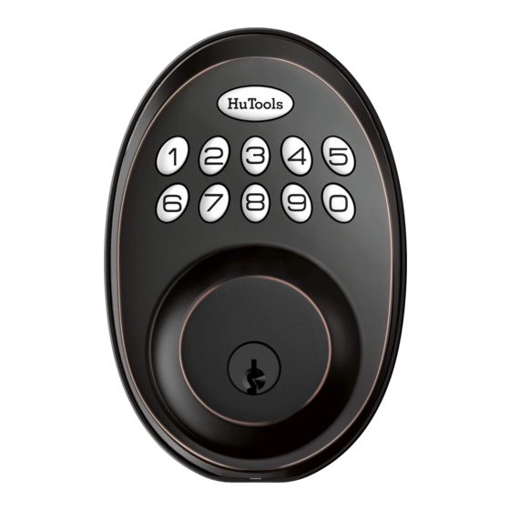
Summary of Contents for HuTools HT01
- Page 1 STEP Determine backset and adjust the latch Hold the latch in front of the door hole, with the latch face flush against the door edge. Is the slotted hole centered in the door hole? Rotate and pull the latch as shown to extend latch. Installa�on Overview Slotted hole is Slotted hole is centered.
- Page 2 STEP STEP Install exterior assembly IMPORTANT: Do not insert the physical key un�l lock is completely installed. With the latch fully retracted (in the unlocked posi�on) , route the cable below A�ach Interior Assembly the latch. to Moun�ng Plate Actual Size and �ghten 3 Screws K.
- Page 3 Programming Instruct ion How To Use Quick Set Up UNLOCK the door from outside IMPORTANT: Each programming step needs to be completed within 5 seconds. Master code User code If you hear 5 rapid beeps that indicates entry error or �me-out. Please start over.
- Page 4 �mes. The temperature range of the HuTools is between -4°F to 131°F. Cause: The latch and strike are misaligned. Solu�on: a. Make sure the bolt hole on the door frame is at least 1 inch Troubleshooting deep so the bolt fully extends.


Need help?
Do you have a question about the HT01 and is the answer not in the manual?
Questions and answers