Asus TUF B360M-PLUS GAMING/BR Manual
Hide thumbs
Also See for TUF B360M-PLUS GAMING/BR:
- Quick start manual (2 pages) ,
- Quick start manual (2 pages)
Table of Contents
Advertisement
Advertisement
Table of Contents

Related Manuals for Asus TUF B360M-PLUS GAMING/BR


Summary of Contents for Asus TUF B360M-PLUS GAMING/BR
- Page 1 TUF B360M-PLUS GAMING/BR...
- Page 2 Product warranty or service will not be extended if: (1) the product is repaired, modified or altered, unless such repair, modification of alteration is authorized in writing by ASUS; or (2) the serial number of the product is defaced or missing.
-
Page 3: Table Of Contents
Contents Safety information ..................iv About this guide ..................iv Package contents ..................vi TUF B360M-PLUS GAMING/BR specifications summary ....... vi Chapter 1 Product introduction Motherboard overview ................1-1 Central Processing Unit (CPU) ..............1-7 System memory ..................1-8 Chapter 2 BIOS information BIOS setup program ................. -
Page 4: Safety Information
Safety information Electrical safety • To prevent electrical shock hazard, disconnect the power cable from the electrical outlet before relocating the system. • When adding or removing devices to or from the system, ensure that the power cables for the devices are unplugged before the signal cables are connected. If possible, disconnect all power cables from the existing system before you add a device. - Page 5 Refer to the following sources for additional information and for product and software updates. ASUS websites The ASUS website provides updated information on ASUS hardware and software products. Refer to the ASUS contact information. Optional documentation Your product package may include optional documentation, such as warranty flyers, that may have been added by your dealer.
-
Page 6: Package Contents
** DDR4 2666MHz and higher memory modules will run at max. 2666MHz on Intel ® Gen. 6-core or higher processors. *** Refer to www.asus.com for the latest Memory QVL (Qualified Vendors List). 1 x PCI Express 3.0/2.0 x16 slot (at x16 mode) Expansion slots 2 x PCI Express 3.0/2.0 x1 slots... - Page 7 - ASUS SafeSlot - Protect your graphics card investment - ASUS ESD Guard: Enhanced ESD protection - ASUS Overvoltage Protection: World-class circuit-protecting power design - ASUS Stainless-Steel Back I/O: 3X corrosion-resistance for greater durability! - ASUS DIGI+ VRM: 5 Phase digital power design Superb Performance...
- Page 8 TUF B360M-PLUS GAMING/BR specifications summary Gaming Scenario Aura - Bright up your Build Audio Features - Audio that roars on the battlefield ASUS Exclusive Features - ASUS Ai Charger - ASUS AI Suite 3 ASUS special - ASUS File Transfer...
- Page 9 1 x Aura RGB Strip header 128Mb Flash ROM, UEFI AMI BIOS, PnP, SM BIOS 3.1, ACPI 6.1, Multi- language BIOS, ASUS EZ Flash 3, CrashFree BIOS 3, F3 My Favorites, Last BIOS Modified log, F4 AURA ON/OFF, F6 Qfan Control, F9 Search, F12 PrintScreen,...
-
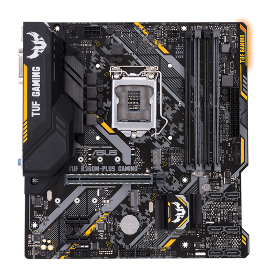
Page 10: Motherboard Overview
2260 2242 U31G1_56 TUF B360M-PLUS GAMING/BR PCIEX16 M.2_2(SOCKET3) SATA6G_2 SATA6G_1 PCIE SATA IRST 2280 2260 2242 Intel ® 1219-V Intel ® B360 PCIEX1_1 SATA6G_4 SATA6G_3 Super PCIEX1_2 AAFP USB914 USB1011 SATA6G_6 SATA6G_5 RGB_HEADER CLRTC PANEL Scan the QR code to get the detailed pin definitions. ASUS TUF B360M-PLUS GAMING/BR... - Page 11 ATX power connectors (24-pin EATXPWR, 8-pin EATX12V) Correctly orient the ATX power supply plugs into these connectors and push down firmly until the connectors completely fit. • For a fully configured system, we recommend that you use a power supply unit (PSU) that complies with ATX 12 V Specification 2.0 (or later version) and provides a minimum power of 350 W. This PSU type has 24-pin and 8-pin power plugs. • We recommend that you use a PSU with higher power output when configuring a system with more power-consuming devices or when you intend to install additional devices. The system may become unstable or may not boot up if the power is inadequate. • If you are uncertain about the minimum power supply requirement for your system, refer to the Recommended Power Supply Wattage Calculator at http://support. asus.com.cn/PowerSupply.aspx?SLanguage=en for details. Intel LGA1151 CPU socket ® Install Intel LGA1151 CPU into this surface mount LGA1151 socket, which is ® designed for 8th Generation Intel Core™ i7 / i5 / i3, Pentium and Celeron ® ® ® processors. For more details, refer to Central Processing Unit (CPU).
- Page 12 To erase the RTC RAM: Turn OFF the computer and unplug the power cord. Use a metal object such as a screwdriver to short the two pins. Plug the power cord and turn ON the computer. PIN 1 Hold down the <Del> key during the boot process and enter BIOS setup to re-enter data. If the steps above do not help, remove the onboard battery and short the two pins again to clear the CMOS RTC RAM data. After clearing the CMOS, reinstall the battery. System panel connector (20-5 pin PANEL) This connector supports several chassis-mounted functions. USB 2.0 connectors (10-1 pin USB1011, USB914) Connect a USB module cable to any of these connectors, then install the module to a slot opening at the back of the system chassis. These USB connectors comply with USB 2.0 specifications and supports up to 480Mbps connection speed. Serial port connector (10-1 pin COM) Connect the serial port module cable to this connector, then install the module to a slot opening at the back of the system chassis. ASUS TUF B360M-PLUS GAMING/BR...
- Page 13 Digital audio connector (4-1 pin SPDIF_OUT) Connect the S/PDIF Out module cable to this connector, then install the module to a slot opening at the back of the system chassis. PIN 1 SPDIF_OUT Front panel audio connector (10-1 pin AAFP) This connector is for a chassis-mounted front panel audio I/O module that supports either HD Audio or legacy AC`97 audio standard. Connect one end of the front panel audio I/O module cable to this connector. • We recommend that you connect a high-definition front panel audio module to this connector to avail of the motherboard’s high-definition audio capability. • If you want to connect a high-definition front panel audio module to this connector, set the Front Panel Type item in the BIOS setup to [HD Audio]. If you want to connect an AC’97 front panel audio module to this connector, set the item to [AC97]. By default, this connector is set to [HD Audio]. PCI Express 3.0/2.0 x1 slots This motherboard has two PCI Express 3.0/2.0 x1 slots that support PCI Express x1 network cards, SCSI cards, and other cards that comply with the PCI Express specifications. M.2 socket 3 M.2(SOCKET3) These sockets allow you to install M.2 (NGFF) SSD modules.
- Page 14 Status Description Status No link 10Mbps connection Orange Linked ORANGE 100Mbps connection Orange (Blinking) Data activity GREEN 1Gbps connection LAN port Orange (Blinking Ready to wake then steady) up from S5 mode Line In port (light blue). This port connects to the tape, CD, DVD player, or other audio sources. Line Out port (lime). This port connects to a headphone or a speaker. In the 4.1, 5.1, and 7.1-channel configurations, the function of this port becomes Front Speaker Out. Microphone port (pink). This port connects to a microphone. Refer to the audio configuration table for the function of the audio ports in 2.1, 4.1, 5.1, or 7.1-channel configuration. ASUS TUF B360M-PLUS GAMING/BR...
- Page 15 Audio 2.1, 4.1, 5.1, or 7.1-channel configuration Headset Port 4.1-channel 5.1-channel 7.1-channel 2.1-channel Light Blue (Rear panel) Line In Rear Speaker Out Rear Speaker Out Rear Speaker Out Lime (Rear panel) Line Out Front Speaker Out Front Speaker Out Front Speaker Out Pink (Rear panel) Mic In Mic In Bass/Center Bass/Center Lime (Front panel) Side Speaker Out To configure a 7.1-channel audio output: Use a chassis with HD audio module in the front panel to support a 7.1-channel audio output. USB 3.1 Gen 2 (up to 10Gbps) ports (teal blue, Type A). These 9-pin Universal Serial Bus 3.1 (USB 3.1) Gen 2 ports are for USB 3.1 Gen 2 devices.
-
Page 16: Central Processing Unit (Cpu)
Central Processing Unit (CPU) This motherboard comes with a surface mount LGA1151 socket designed for the 8th Generation Intel Core™ i7 / Core™ i5 / Core™ i3, ® Pentium and Celeron processors. ® ® Unplug all power cables before installing the CPU. • Ensure that you install the correct CPU designed for the LGA1151 socket only. DO NOT install a CPU designed for LGA1150, LGA1155 and LGA1156 sockets on the LGA1151 socket. • Upon purchase of the motherboard, ensure that the PnP cap is on the socket and the socket contacts are not bent. Contact your retailer immediately if the PnP cap is missing, or if you see any damage to the PnP cap/socket contacts/motherboard components. • Keep the cap after installing the motherboard. ASUS will process Return Merchandise Authorization (RMA) requests only if the motherboard comes with the cap on the LGA1151 socket. • The product warranty does not cover damage to the socket contacts resulting from incorrect CPU installation/removal, or misplacement/loss/incorrect removal of the PnP cap. Installing the CPU Apply the Thermal Interface Material to the CPU heatsink and CPU before you install the heatsink and fan if necessary. ASUS TUF B360M-PLUS GAMING/BR... -
Page 17: System Memory
DIMM_A2* Channel A DIMM_A1 and DIMM_A2* DIMM_B1 Channel B DIMM_B1 and DIMM_B2* DIMM_B2* • You may install varying memory sizes in Channel A and Channel B. The system maps the total size of the lower-sized channel for the dual-channel configuration. Any excess memory from the higher-sized channel is then mapped for single-channel operation. • Always install DIMMs with the same CAS latency. For optimal compatibility, we recommend that you install memory modules of the same version or date code (D/C) from the same vendor. Check with the retailer to get the correct memory modules. • DDR4 2666MHz and higher memory modules will run at max. 2666MHz on Intel 8th ® Generation 6-core or higher processors. • Memory modules with memory frequency higher than 2133/2400/2666 MHz and its corresponding timing or the loaded X.M.P. Profile is not the JEDEC memory standard. The stability and compatibility of these memory modules depend on the CPU’s capabilities and other installed devices. • The default memory operation frequency is dependent on its Serial Presence Detect (SPD), which is the standard way of accessing information from a memory module. Under the default state, some memory modules for overclocking may operate at a lower frequency than the vendor-marked value. • For system stability, use a more efficient memory cooling system to support a full memory load (4 DIMMs). • Refer to www.asus.com for the latest Memory QVL (Qualified Vendors List) Chapter 1: Product introduction... - Page 18 Recommended memory configurations DIMM_B1 DIMM_B2* DIMM_B2* DIMM_A1 DIMM_A2* DIMM_A2* DIMM_A2* Installing a DIMM To remove a DIMM ASUS TUF B360M-PLUS GAMING/BR...
-
Page 19: Chapter 2 Bios Information
To enter BIOS Setup after POST: Press <Ctrl>+<Alt>+<Del> simultaneously. Press the reset button on the system chassis. Press the power button to turn the system off then back on. Do this option only if you failed to enter BIOS Setup using the first two options. Using the power button, reset button, or the <Ctrl>+<Alt>+<Del> keys to force reset from a running operating system can cause damage to your data or system. We recommend you always shut down the system properly from the operating system. • The BIOS setup screens shown in this section are for reference purposes only, and may not exactly match what you see on your screen. • Visit the ASUS website at www.asus.com to download the latest BIOS file for this motherboard. • If the system becomes unstable after changing any BIOS setting, load the default settings to ensure system compatibility and stability. Select the Load Optimized Defaults item under the Exit menu or press hotkey F5. • If the system fails to boot after changing any BIOS setting, try to clear the CMOS and reset the motherboard to the default value. See section Motherboard overview for information on how to erase the RTC RAM. BIOS menu screen The BIOS setup program can be used under two modes: EZ Mode and Advanced Mode. Press <F7> to change between the two modes. ASUS TUF B360M-PLUS GAMING/BR... -
Page 20: Ez Mode
EZ Mode By default, the EZ Mode screen appears when you enter the BIOS setup program. The EZ Mode provides you an overview of the basic system information, and allows you to select the display language, system performance mode, fan profile and boot device priority. To access the Advanced Mode, click Advanced Mode(F7) or press <F7>. The default screen for entering the BIOS setup program can be changed. Refer to the Setup Mode item under the Boot menu for details. Displays the CPU/ Selects the display language of Displays the system properties motherboard the BIOS setup program of the selected mode. Click temperature, CPU <Enter> to switch EZ System Searches by BIOS item voltage output, CPU/ Tuning modes... -
Page 21: Advanced Mode
MyFavorite AURA ON/OFF Search Language Pop-up Last modified Searches Sub-menu item General help Scroll bar window settings Menu items Hotkeys Configuration Goes back to fields EZ Mode Displays the CPU temperature, CPU and memory voltage output ASUS TUF B360M-PLUS GAMING/BR... -
Page 22: Exit Menu
Search on FAQ Move your mouse over this button to show a QR code. Scan this QR code with your mobile device to connect to the ASUS BIOS FAQ web page. You can also scan the QR code below. Exit menu The Exit menu items allow you to load the optimal default values for the BIOS items, and save or discard your changes to the BIOS items. Load Optimized Defaults This option allows you to load the default values for each of the parameters on the Setup menus. When you select this option or if you press <F5>, a confirmation window appears. Select OK to load the default values. Save Changes & Reset Once you are finished making your selections, choose this option from the Exit menu to ensure the values you selected are saved. When you select this option or if you press <F10>, a confirmation window appears. Select OK to save changes and exit. Discard Changes and Exit This option allows you to exit the Setup program without saving your changes. When you select this option or if you press <Esc>, a confirmation window appears. Select OK to discard changes and exit. Launch EFI Shell from USB drives This option allows you to attempt to launch the EFI Shell application (shellx64.efi) from one of the available USB devices. Chapter 2: Getting started... -
Page 23: Appendix
: (1) l’appareil ne doit pas produire de brouillage, et (2) l’utilisateur de l’appareil doit accepter tout brouillage radioélectrique subi, même si le brouillage est susceptible d’en compromettre le fonctionnement. CAN ICES-3(B)/NMB-3(B) ASUS TUF B360M-PLUS GAMING/BR... - Page 24 ASUS Recycling/Takeback Services ASUS recycling and takeback programs come from our commitment to the highest standards for protecting our environment. We believe in providing solutions for you to be able to responsibly recycle our products, batteries, other components as well as the packaging materials.
- Page 25 Unless required by applicable law or agreed to in writing, software distributed under the License is distributed on an “AS IS” BASIS, WITHOUT WARRANTIES OR CONDITIONS OF ANY KIND, either express or implied. See the License for the specific language governing permissions and limitations under the License. ASUS TUF B360M-PLUS GAMING/BR...
- Page 26 доступний на: www.asus.com/support Cijeli tekst EU izjave o sukladnosti dostupan je na: www.asus.com/support Türkçe AsusTek Computer Inc., bu aygıtın temel gereksinimlerle ve ilişkili Čeština Společnost ASUSTeK Computer Inc. tímto prohlašuje, že toto Yönergelerin diğer ilgili koşullarıyla uyumlu olduğunu beyan eder.
-
Page 27: Asus Contact Information
+1-510-739-3777 +1-510-608-4555 Web site http://www.asus.com/us/ Technical Support Support fax +1-812-284-0883 Telephone +1-812-282-2787 Online support http://qr.asus.com/techserv ASUS COMPUTER GmbH (Germany and Austria) Address Harkort Str. 21-23, 40880 Ratingen, Germany +49-2102-959931 Web site http://www.asus.com/de Online contact http://eu-rma.asus.com/sales Technical Support Telephone +49-2102-5789555 Support Fax... - Page 28 FCC COMPLIANCE INFROMATION Per FCC Part 2 Section 2.1077 Asus Computer International Responsible Party: 800 Corporate Way, Fremont CA 94539. Address: Phone/Fax No: (510)739-3777/(510)608-4555 hereby declares that the product Product Name : Motherboard Model Number : TUF B360M-PLUS GAMING compliance statement: This device complies with part 15 of the FCC Rules.
Need help?
Do you have a question about the TUF B360M-PLUS GAMING/BR and is the answer not in the manual?
Questions and answers
ik heb een groter geheugen in mijn b360-pus board gezet van 8 gbt naar 2 x 16 gbt maar nu heb ik geen netwerk toegang meer
The Asus TUF B360M-PLUS GAMING/BR motherboard requires memory modules with identical specifications for compatibility. If the new memory modules differ in specifications, such as CAS latency or version, it could cause system instability, which may affect various hardware functions, including network access. To resolve this, ensure that the memory modules are of the same type, frequency, CAS latency, and from the same vendor, as recommended in the manual.
This answer is automatically generated