
Related Manuals for G.R.A.S. 41AC-4 LEMO

Summary of Contents for G.R.A.S. 41AC-4 LEMO
- Page 1 Instruction Manual G.R.A.S. 41AC-4 LEMO Outdoor Microphone for Community and Airport Noise (0 V pol.) www.gras.dk LI0171 – 18 February 2015...
- Page 2 Revision History Any feedback or questions about this document are welcome at gras@gras.dk. Revision Date Description 18 February 2015 First edition Copyright Notice © 2015 G.R.A.S. Sound & Vibration A/S http://www.gras.dk Any technical documentation that is made available by G.R.A.S. is the copyrighted work of G.R.A.S.
-
Page 3: Table Of Contents
Contents Introduction .................. 4 Delivered Items ................4 Installation .................. 6 System Integration ..............12 Maintenance ................12 Accessories ................13 Specifications ................13 Calibration, Warranty and Service ........... 17 LI0171 – 18 February 2015... -
Page 4: Introduction
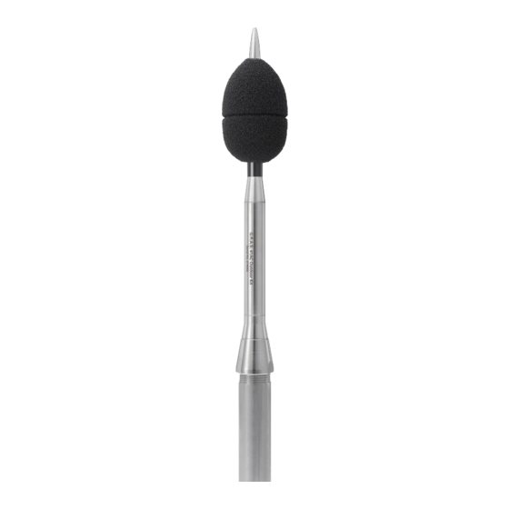
Introduction The G.R.A.S. 41AC-4 Outdoor Microphone for Community & Airport Noise is a precision micro- phone set (IEC 61672-1) for monitoring community noise and the noise of overhead aircraft. It can be used for monitoring of noise with 90 degrees of incidence, typically community noise. With the proper correction data, it can be used for 0 degrees of incidence, typically noise from overhead aircraft. - Page 5 41AC-4 is delivered pre-assembled except for the windscreen and thread adapter. ½" microphone 40AE-S2 Lower housing Upper housing Windscreen AM0378 O-ring OR2038 Preamplifier 26AK 2-piece 1” pole mount Top cone adapter RA0286 Release tube GR1794 Tripod and thread adapter SK0017 Fig.
-
Page 6: Installation
Installation Mounting 41AC-4 on Tripod or Pole Mount Adapter The 41AC-4 is designed for permanent installation and therefore comes with an adapter for mounting on a 1” pole. See Fig. 2 and Fig. 3, 3. The 41AC-4’s housing is attached to the mount- ing fittings with a M18 x 1.5 thread. - Page 7 Attaching the Lower Housing 1. Unscrew the upper part from the lower body. 2. Set the upper part aside and ensure that it is protected from dirt and moisture. 3. Slide the microphone cable through the adapter and through the lower housing, and screw the housing onto the pole mount adapter.
- Page 8 Connecting the Cable to the Preamplifier Important. Before connecting cable and preamplifier, you must ensure that the upper housing can turn independently of microphone, preamplifier and cable. This is done by loosening the microphone from the preamplifier by approximately half a turn. Doing this ensures that the microphone-preamplifier and the preamplifier-cable connections are not subjected to strain when the upper housing is screwed onto the lower housing.
- Page 9 Mounting the Upper Housing and the Top Cone When the microphone has been loosened from the preamplifier, you can safely mount the upper housing onto the lower housing and subsequently mount the top cone. 1. Screw the upper part of the housing onto the lower part. 2.
- Page 10 Mounting the Windscreen The windscreen is lined with a plastic tube that ensures that it can be positioned correctly in relation to the microphone’s diaphragm. • When pushed down, the windscreen tube is prevented from going too far by the upper hous- ing’s conical shape.
- Page 11 Disassembly You can disassemble the 41AC-4 by reversing the procedure described on the preceding pages. Two points need special attention: Removing the Windscreen The windscreen tube is held in place by a locking mechanism. Therefore, some force must be applied to slide the tube back up. See Fig. 7a. 1.
-
Page 12: System Integration
System Integration Setting the 41AC-4 for 90 or 0 Degrees of Incidence The 41AC-4 is designed to be mounted vertically, as described in the previous sections. Mounted in this way, it can be set up for measurement at either 90 degrees or 0 degrees of incidence. The correction data contained on the USB flash drive that is part of the delivery must be used if the 41AC-4 is used for 0 degrees of incidence. -
Page 13: Accessories
Accessories These accessories must be ordered separately: Intelligent Pistonphone 42AP Pistonphone 42AA Sound Calibrator 42AB 3 m LEMO 7-pin - LEMO 7-pin Cable AA0008 10 m LEMO 7-pin - LEMO 7-pin Cable AA0009 30 m LEMO 7-pin - LEMO 7-pin Cable AA0012 100 m LEMO 7-pin - LEMO 7-pin Cable AA0014... - Page 14 Not used Fig. 8. 7-pin LEMO 1B male connector (external view) on the 41AC-4s preamplifier and output cable. 1” pipe thread (ISO 228/1-G1) 295 mm/11 / in 343 mm/13 / in 12 mm/ / in Fig. 9. When mounted on a pipe, the top of the 41AC will be elevated 343 mm above the pipe. LI0171 –...
- Page 15 Frequency Response and Directional Response 41AC Typical Frequency Response Typical frequecy responce 90° incidence 90° incidence 0° incidence 0° incidence 0° incidence with corr. 0° incidence with correction IEC 61672-1 tolerance + IEC expanded lim+ IEC expanded lim- IEC 61672-1 tolerance - IEC lim + IEC 61672-1 accept.
- Page 16 Acceptance limits for deviations of directional response ±90° Directional Response Measurements 41AC w. windscreen 0° and 90° Incidence 0º incidence Lim dev ±90º 0° incidence 0° incidence 90° incidence 90° incidence Lim w. uncertanty ±90º IEC 61672-1 tolerance Lim dev ±90º IEC 61672-1 acccep.
-
Page 17: Calibration, Warranty And Service
Calibration, Warranty and Service Calibration Before leaving the factory, all G.R.A.S. products are calibrated in a controlled laboratory environ- ment using traceable calibration equipment. An individual test certificate stating the sensitivity and frequency response is included with each product. Warranty All G.R.A.S.
Need help?
Do you have a question about the 41AC-4 LEMO and is the answer not in the manual?
Questions and answers