Sign In
Upload
Download
Table of Contents
Contents
Add to my manuals
Delete from my manuals
Share
URL of this page:
HTML Link:
Bookmark this page
Add
Manual will be automatically added to "My Manuals"
Print this page
×
Bookmark added
×
Added to my manuals
Manuals
Brands
B+K precision Manuals
Power Supply
1865B
Programming manual
B+K precision 1865B Programming Manual
Switching dc power supplies
Hide thumbs
1
Table Of Contents
2
3
4
5
6
7
8
9
10
11
12
13
14
15
page
of
15
Go
/
15
Contents
Table of Contents
Bookmarks
Table of Contents
Table of Contents
1 USB Interface Connection
USB (Virtual COM) Configuration
2 PC Software
General Functions and Display
External Timed Program
Internal Preset Memory
Data Log
Settings
Power Supply Calibration
3 Command Set
Advertisement
Quick Links
Download this manual
Test Equipment Depot - 800.517.8431 - 99 Washington Street Melrose, MA 02176
TestEquipmentDepot.com
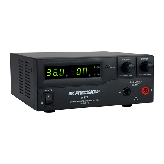
Model: 1685B, 1687B, 1688B
Switching DC Power Supplies
PROGRAMMING MANUAL
Table of
Contents
Previous
Page
Next
Page
1
2
3
4
5
Advertisement
Table of Contents
Need help?
Do you have a question about the 1865B and is the answer not in the manual?
Ask a question
Questions and answers
Related Manuals for B+K precision 1865B
Power Supply B+K precision 1653A Instruction Manual
Isolated-variable ac power supply (81 pages)
Power Supply B+K precision 1680 Instruction Manual
(6 pages)
Power Supply B+K precision 1680 Instruction Manual
(6 pages)
Power Supply B+K precision 1610 Instruction Manual
(30 pages)
Power Supply B+K precision 1635 Instruction Manual
Dc power supply with led display (34 pages)
Power Supply B+K precision 1601 Instruction Manual
Regulated dc power supply (14 pages)
Power Supply B+K precision 1687B Programming Manual
Switching dc power supplies (15 pages)
Power Supply B+K precision 1688B Programming Manual
Switching dc power supplies (15 pages)
Power Supply B+K precision DYNASCAN 1650 Instruction Manual
Tri-output laboratory power supply (32 pages)
This manual is also suitable for:
1687b
1688b
Table of Contents
Print
Rename the bookmark
Delete bookmark?
Delete from my manuals?
Login
Sign In
OR
Sign in with Facebook
Sign in with Google
Upload manual
Upload from disk
Upload from URL


Need help?
Do you have a question about the 1865B and is the answer not in the manual?
Questions and answers