
Related Manuals for Sys Tec Electronic USB-CANmodul

Summary of Contents for Sys Tec Electronic USB-CANmodul
- Page 1 USB-CANmodul Systems Manual Edition March 2001 A Product of PHYTEC Technologie Holding AG...
- Page 2 SYS TEC electronic GmbH neither gives any guarantee nor accepts any liability whatsoever for consequential damages resulting from the use of this manual or its associated product. SYS TEC Electronic GmbH reserves the right to alter the information contained herein without prior notification and accepts no responsibility for any damages which might result.
-
Page 3: Table Of Contents
Preface ......................3 Introduction ..................5 Getting Started..................9 2.1 Installation of the USB-CANmodul ..........9 2.1.1 Software Installation............9 2.1.2 Connecting the USB-CANmodul to the Host-PC ..10 2.1.3 Checking the Device Installation........11 2.1.4 Device Number Allocation..........12 2.1.5 Connection to a CAN Network ........13 2.1.6 Starting PCANView (USBCAN) ........14... - Page 4 Figure 10: Dialog Box Message Filter Configuration ......... 25 Figure 11: PCANView (USBCAN) with Messages ........26 Figure 12: Software State Diagram.............. 30 Table 1: States of the LEDs on the USB-CANmodul ......17 Table 2: Pinout of the DB-9 Connector............ 17 Table 3: Configuration of the CAN Power Supply Jumpers ....
-
Page 5: Preface
Preface Preface This USB-CANmodul Systems Manual describes the board's design and function. Precise specifications for the on-board microcontrollers can be found in the enclosed microcontroller Data Sheet/User's Man- ual. In this manual, and in the attached schematics, low active signals are denoted by a "/"... - Page 6 PHYTEC America LLC August-Bebel-Str. 29 255 Ericksen Avenue NE D-07973 Greiz Bainbridge Island, WA GERMANY 98110 http://www.systec-electronic.de http://www.phytec.com/ Web Site: info@systec-electronic.de info@phytec.com e-mail: Voice: +(49) 3661-6279-0 1 (800) 278-9913 Fax: +(49) 3661-63248 1 (206) 780-9135 SYS TEC electronic GmbH 2001 L-487e_6...
-
Page 7: Introduction
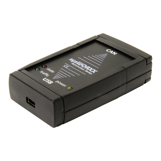
CANmodul. The USB interface enables data transfer with a rate of up to 12 MBit/s. With a uniform connector for all device types, the system is absolutely user friendly. Once the USB-CANmodul is connected to the host-PC, the operating system reads the configuration data and automatically loads the device driver. - Page 8 USB interface (Anchor Chips AN2131QC) and a CAN controller (Philips SJA1000) which transmits and receives the CAN message. Power for the USB-CANmodul is supplied through either the CAN network or the USB bus. The module has two LEDs, one for status display and one for power.
- Page 9 USBCAN.SYS supports the various functions of the USB- CANmodul ! User-Mode driver for Windows 98/2000: USBCAN.DLL for easy use of the USB-CANmodul functions ! Up to 10 USB-CANmoduls can be supported by these drivers ! Tools for Windows 98 / 2000: UCAN Config –...
- Page 10 USB-CANmodul SYS TEC electronic GmbH 2001 L-487e_6...
-
Page 11: Getting Started
• • • • installing the USB-CANmodul • • • • software installation • • • • connecting the USB-CANmodul to the host-PC • • • • connecting the USB-CANmodul to a CAN network • using PCANView (USBCAN) 2.1 Installation of the USB-CANmodul Ensure that the individual components are not damaged. -
Page 12: Connecting The Usb-Canmodul To The Host-Pc
2.1.2 Connecting the USB-CANmodul to the Host-PC Connecting the USB-CANmodul to the host-PC is simple. • Start the host-PC. • Connect the USB-CANmodul to your computer using the included USB cable • Windows automatically detects the USB-CANmodul. A window with the message “Unknown device” appears. Then the operating system automatically searches for the appropriate driver. -
Page 13: Checking The Device Installation
• Choose the tab “Device Manager” at the top. Click on the pull- down menu “Universal Serial Bus Controller”. If the device “Systec USB-CANmodul (usbcan.sys) ” is shown in the list, the new USB device has been detected properly. This is shown in the... -
Page 14: Device Number Allocation
• Start the configuration utility using the Windows Start button and browse to Programs \ USB-CANmodul Utilities \ UCAN Config. • This utility lists the USB-CANmodul’s by serial number and device number. The device number is set to zero by the manufacturer. -
Page 15: Connection To A Can Network
CAN cable between CAN_L (pin 2) and CAN_H (pin 7) is required to ensure proper signal transmission. The default setting of the USB-CANmodul at time of delivery configures the CAN transceiver to operate optically isolated. For this reason, the power for the CAN transceiver has to be supplied via the CAN bus. -
Page 16: Starting Pcanview (Usbcan)
Dialog Box with Hardware Configuration • Select the baudrate of your CAN network in the Baudrate box and the Device Number. The entry any selects the USB-CANmodul that is found first by Windows. Click on the OK button to enable these settings. -
Page 17: Figure 5: Dialog Box Message Filter Configuration
• In this message box you can select Standard (11-bit) or Extended (29-bit) CAN identifier and message filters, if desired. Click on the OK button to enable these settings. • The PCANView (USBCAN) main window will appear: SYS TEC electronic GmbH 2001 L-487e_6... -
Page 18: Figure 6: Pcanview (Usbcan) Main Window
CAN signals that are received from a node • Transmit: monitors CAN signals sent from the host-PC to the CAN network via the USB-CANmodul Refer to section 3.1.2 for complete and detailed description of the PCANView (USBCAN) utility program. -
Page 19: Status Leds On The Usb-Canmodul
An error occurred on the (at. 2 Hz) USB-CANmodul. Table 1: States of the LEDs on the USB-CANmodul 2.3 CAN Supply Voltage The default setting for the CAN supply voltage is optically isolated. The voltage for the CAN transceiver and the opto-coupler must be supplied via the CAN cable. -
Page 20: Figure 7: Location And Numbering Of The Jumpers
CAN_H are necessary. To change between CAN power supply via USB or via the CAN bus, two insertable jumpers are available on the USB-CANmodul. Remove the four screws on the bottom of the module and remove the upper part of the case carefully to configure the required jumpers. - Page 21 Getting Started CAN Power Supply Via CAN bus (pin 3 and 9) Via USB bus Other settings are not allowed. Table 3: Configuration of the CAN Power Supply Jumpers SYS TEC electronic GmbH 2001 L-487e_6...
- Page 22 USB-CANmodul SYS TEC electronic GmbH 2001 L-487e_6...
-
Page 23: Software Support
3.1 Tools for the USB-CANmodul 3.1.1 UCAN Config for Windows It is possible to use more than one USB-CANmodul with one application, or from several applications from one host. Each module has a device number that the software in the host-PC determines in order to connect to the correct module. -
Page 24: Figure 8: Ucan Config Utility
The device number can then be changed within this input field. Values from 0 to 254 are valid. Click on the Change button to program the new value into the USB-CANmodul. Invalid values will be recognized by the program and not be accepted. - Page 25 Software While this utility is running, you can add more USB-CANmoduls. The program will recognize the USB-CANmodul, and you can update the module list by pressing the refresh button. To exit the UCAN Config utility click on Close. SYS TEC electronic GmbH 2001...
-
Page 26: Pcanview (Usbcan) For Windows
Dialog Box with Hardware Configuration • Select the baudrate of your CAN network in the Baudrate box and the Device Number. The entry any selects the USB-CANmodul that is found first by Windows. Click on the OK button to enable these settings. -
Page 27: Figure 10: Dialog Box Message Filter Configuration
• In this message box you can select Standard (11-bit) or Extended (29-bit) CAN identifier and message filters if desired. Click on the OK button to enable these settings. • The PCANView (USBCAN) main window will appear: SYS TEC electronic GmbH 2001 L-487e_6... -
Page 28: Figure 11: Pcanview (Usbcan) With Messages
This screen is divided into two sections: Receive and Transmit • Receive: monitors CAN signals that are received from a node • Transmit: monitors CAN signals sent from the host-PC to the CAN network via the USB-CANmodul Receive Section The Receive section provides the following information: • Message:... - Page 29 In order to edit the Transmit list, the following menu commands are available: • Transmit | New...: Create a new transmit message. The editor window for the new message is shown. • Transmit | Delete: Delete the currently selected message from SYS TEC electronic GmbH 2001 L-487e_6...
- Page 30 • Transmit | Edit...: Edit the currently selected message. • Transmit | Clear all: Delete the entire transmit list. • Program | Reset: Reset the message counters and reset the connected USB-CANmodul. Deletes the receive list. SYS TEC electronic GmbH 2001 L-487e_6...
-
Page 31: Dynamic Linked Library
With USBCAN32.DLL, it is possible to use 10 USB-simultaneously with one application program, as well as with several application programs. However, it is not possible to use one USB-CANmodul with several application programs. Three states within the software are generated for each USB- CANmodul when using this DLL. -
Page 32: Figure 12: Software State Diagram
Calling the library function UcanInitHardware () causes the software to change into the HW_INIT state. This state contains all resources required for communication with the USB-CANmodul. It is not possible to transmit or to receive CAN messages in this state. -
Page 33: Software State Functions
If several USB-CANmoduls are used in one application, these states have to be considered for each USB-CANmodul that is used. If the first USB-CANmodul is in the state CAN_INIT, the second one can still be in the DLL_INIT state. -
Page 34: Functions Of The Usbcan32.Dll
Bit 4 to 7: most significant digits of the version number in binary format Bit 8 to 14: reserved Bit 15: 1 = customer specific version SYS TEC electronic GmbH 2001 L-487e_6... - Page 35 BYTE STDCALL UcanInitHwConnectControl (tConnectControlFkt fpConnectControlFkt_p); Usability: DLL_INIT Parameter: fpConnectControlFkt_p: Address to the callback function that has to be called if a new USB-CANmodul is connected or disconnected. This address may not be zero! Return value: Error code of the function. USBCAN_SUCCESSFUL USBCAN_ERR_RESOURCE Description: Initializes the supervision for recently connected USB-CANmoduls.
- Page 36 Description: This function finishes the supervision of the recently connected or disconnected USB-CANmoduls. This function must be called after the function UcanInitHwConnectControl () was called within an application and before closing this application. SYS TEC electronic GmbH 2001 L-487e_6...
- Page 37 Parameter: pUcanHandle_p: Pointer to the variable for the USB-CAN Handle. This pointer may not be ZERO! bDeviceNr_p: Device number of the USB-CANmodul (0 – 254). The value USBCAN_ANY_MODULE (= 255) makes sure that the first allocated USB-CANmodul is used. fpCallbackFkt_p: Address to the callback function of this USB- CANmodul.
- Page 38 USB-CANmodul Description: Initializes a USB-CANmodul. The software changes into the state HW_INIT. From this point, other functions as they are defined in Table 4 can be called. If the function was executed successfully, the function transfers USB-CAN handle variable *pUcabHandle_p. Other functions have to be called with this handle.
- Page 39 USBCAN_ERR_MAXINSTANCES USBCAN_ERR_ILLHANDLE Description: Shuts down an initialized USB-CANmodul. The software returns to the state DLL_INIT. After the function call, the USB-CAN handle is not valid. That means, execution of the valid functions (see Table 4) for HW_INIT is no longer possible.
- Page 40 USBCAN_ERRCMD_NOTEQU USBCAN_ERRCMD_REGTST USBCAN_ERRCMD_ILLCMD Description: Initializes the CAN interface of a USB-CANmodul. The software changes into the state CAN_INIT. Now it is possible to transmit and receive CAN messages. Table 4 shows the possible functions in this state. SYS TEC electronic GmbH 2001...
- Page 41 USBCAN_SUCCESSFUL USBCAN_ERR_MAXINSTANCES USBCAN_ERR_ILLHANDLE USBCAN_ERR_CANNOTINIT USBCAN_ERR_BUSY USBCAN_ERR_IOFAILED USBCAN_ERRCMD_NOTEQU USBCAN_ERRCMD_ILLCMD Description: Resets the CAN controller in the USB-CANmodul and erases the CAN message buffer. This function needs to be called if a BUSOFF event occurred. SYS TEC electronic GmbH 2001 L-487e_6...
- Page 42 USBCAN_ERRCMD_NOTEQU USBCAN_ERRCMD_ILLCMD Description: Shuts down the CAN interface of a USB-CANmodul. This function sets the operating voltage of the CAN controller to 0 V. After calling this function, all CAN messages transferred on the CAN bus are ignored and not transferred to the PC.
- Page 43 // Baud Rate Register 1 BYTE m_bOCR; // Output Control Register DWORD m_dwAMR; // Acceptance Mask Register DWORD m_dwACR; // Acceptance Code Register } tUcanHardwareInfo; Return value: Error code of the function. USBCAN_SUCCESSFUL USBCAN_ERR_MAXINSTANCES USBCAN_ERR_ILLHANDLE USBCAN_ERR_ILLPARAM SYS TEC electronic GmbH 2001 L-487e_6...
- Page 44 USB-CANmodul Description: Returns the hardware information of a USB-CANmodul. This function is especially useful if a USB-CANmodul has been initialized with the device number USBCAN_ANY_MODULE. Afterwards, the hardware information contains the device number of the initialized USB-CANmodul. Example: BYTE bRet;...
- Page 45 Usability: HW_INIT, CAN_INIT Parameter: UcanHandle_p: USB-CAN handle received with the function UcanInitHardware (). pStatus_p: Error status of the USB-CANmodul. typedef struct WORD m_wCanStatus; // present CAN status WORD m_wUsbStatus; // present USB status } tStatusStruct; Return values: Error code of the function.
- Page 46 Returns the error status from the USB-CANmodul. If an error occurred on the USB-CANmodul, the red status LED starts blinking and a status information is returned to the PC. If a callback function has been handed over to the function UcanInitHardware (), this...
- Page 47 USB errors are handled by the Windows operating system. Error Warning Limit of the SJA1000 CAN controller, default value is 96. Refer to SJA1000 data sheet. Error Counter exceeds the protocol-defined level of 127. Refer to SJA1000 data sheet. SYS TEC electronic GmbH 2001 L-487e_6...
- Page 48 Baud rate register 0 bBTR1_p: Baud rate register 1 Return value: Error code of the function. USBCAN_SUCCESSFUL USBCAN_ERR_MAXINSTANCES USBCAN_ERR_ILLHANDLE USBCAN_ERR_CANNOTINIT USBCAN_ERR_BUSY USBCAN_ERR_IOFAILED USBCAN_ERRCMD_NOTEQU USBCAN_ERRCMD_ILLCMD Description: Changes the baud rate configuration of the USB-CANmodul. SYS TEC electronic GmbH 2001 L-487e_6...
- Page 49 UcanInitHardware (). dwAMR_p: Acceptance Mask Register dwACR_p: Acceptance Code Register Return value: Error code of the function. USBCAN_SUCCESSFUL USBCAN_ERR_MAXINSTANCES USBCAN_ERR_ILLHANDLE USBCAN_ERR_CANNOTINIT USBCAN_ERR_BUSY USBCAN_ERR_IOFAILED USBCAN_ERRCMD_NOTEQU USBCAN_ERRCMD_ILLCMD Description: Changes the acceptance Mask Register of the USB-CANmodul. SYS TEC electronic GmbH 2001 L-487e_6...
-
Page 50: Usability: Can_Init
DWORD m_dwID; // CAN identifier BYTE m_bFF; // CAN frame format BYTE m_bDLC; // CAN data length code BYTE m_bData[8]; // CAN data DWORD m_dwTime; // Receipt time in ms } tCanMsgStruct; SYS TEC electronic GmbH 2001 L-487e_6... - Page 51 // no warning? print error if (!(bRet & USBCAN_WARNING)) PrintError (bRet); else // valid message in CanMsg? if (bRet != USBCAN_WARN_NODATA) // print CAN message PrintCanMsg (&CanMsg); // print warning PrintWarning (bRet); SYS TEC electronic GmbH 2001 L-487e_6...
-
Page 52: Return Value: Error Code Of The Function
// CAN data DWORD m_dwTime; // has no meaning in this function } tCanMsgStruct; Return value: Error code of the function. USBCAN_SUCCESSFUL USBCAN_ERR_MAXINSTANCES USBCAN_ERR_ILLHANDLE USBCAN_ERR_CANNOTINIT USBCAN_ERR_ILLPARAM USBCAN_ERR_DLL_TXFULL Description: Transmits a CAN message through the USB-CANmodul. SYS TEC electronic GmbH 2001 L-487e_6... -
Page 53: Error Codes Of The Functions
This message returns if the function is executed successfully. USBCAN_ERR_RESOURCE Value: 0x01 Description: This error message returns if one resource could not be generated. In this case the term resource means memory and handles provided by Windows. SYS TEC electronic GmbH 2001 L-487e_6... - Page 54 Application 3 receives this error message. USBCAN_ERR_HWINUSE Value: 0x03 Description: An application tries to initialize a USB-CANmodul with the device number x. If this module has already been initialized by its own or by another application, this error message is returned. USBCAN_ERR_ILLVERSION Value: 0x04...
- Page 55 USBCAN_ERR_ILLHW Value: 0x05 Description: This error message returns if a USB-CANmodul with the device number x is not found. If the function UcanInitHardware () has been called with the device number USBCAN_ANY_MODULE, and the error code appears, it indicates that no module is connected to the PC or all connected modules are already in use.
- Page 56 USBCAN_ERR_TIMEOUT Value: 0x09 Description: This error message occurs if the function transmits a command to the USB-CANmodul but no answer is returned. To solve this problem, close the application, disconnect the USB-CANmodul, and connect it again. USBCAN_ERR_IOFAILED Value: 0x0a...
-
Page 57: Usbcan_Err_Maxinstances
In this case, it is not possible to initialize a USB- CANmodul. USBCAN_ERR_CANNOTINIT 55 Value: 0x0d Description If a USB-CANmodul is initialized with the function UcanInitHardware (), the software changes into the state HW_INIT. Functions like UcanReadCanMsg () UcanWriteCanMsg () return this error message while in HW_INIT state. -
Page 58: Usbcan_Errcmd_Notequ
Description: This error code occurs during communication between the PC and a USB-CANmodul. The PC sends a command to the USB- CANmodul, then the module executes the command and returns a response to the PC. This error message returns if the answer does not correspond to the command. - Page 59 Software USBCAN_ERRCMD_EEPROM Value: 0x43 Description: The USB-CANmodul has a serial EEPROM. This EEPROM contains the device number and the serial number. If an error occurs while reading these values, this error message is returned. USBCAN_WARN_NODATA Value: 0x80 Description: If the function UcanReadCanMsg () returns with this warning, it is an indication that the receive buffer contains no CAN messages.
- Page 60 Value: 0x82 Description: The USBCAN32.DLL automatically requests CAN messages from the USB-CANmodul and stores the messages into a buffer of the DLL. If more CAN messages are received than the DLL buffer size allows, this error message returns and CAN messages lost.
-
Page 61: Baud Rate Configuration
// AMR: all messages received 0x0000); // ACR // Error? print error if (bRet) PrintError (bRet); Configuration of other baud rates is also possible. Refer to the SJA1000 Data Sheet for detailed description. SYS TEC electronic GmbH 2001 L-487e_6... -
Page 62: Can Messages Filter Function
The corresponding bit of the CAN identifier has to be 0. The corresponding bit of the CAN identifier has to be 1. The corresponding bit of the CAN identifier can be either 0 or 1. SYS TEC electronic GmbH 2001 L-487e_6... - Page 63 (TRUE) or a 11-bit message (FALSE). The parameter can_id shows the filter value as CAN identifier. The parameter rtr can be used to filter RTR frames. This parameter can be TRUE (=1) or FALSE (=0). SYS TEC electronic GmbH 2001 L-487e_6...
- Page 64 CAN messages with a 29-bit identifier are filtered with the same configuration. In this case AMR and ACR are interpreted in a different way. In this configuration, CAN messages with the 29-bit identifiers from 0x0C000000 to 0FFFFFFF will be received. SYS TEC electronic GmbH 2001 L-487e_6...
-
Page 65: Using The Callback Functions
Handle is invalid; in other instances, the parameter is 0. Description: This callback function informs the application program if a new USB- CANmodul is connected to the PC, or a connected USB-CANmodul has been disconnected. UcanCallbackFkt Syntax: void STDCALL UcanCallbackFkt (tUcanHandle UcanHandle_p, BYTE bEvent_p);... - Page 66 USB-CANmodul UcanHandle_p: USB-CAN handle of the USB-CANmodul where the event occurred. This handle is returned with the function UcanInitHardware (). bEvent_p: Event which occurred. USBCAN_EVENT_INITHW USBCAN_EVENT_INITCAN USBCAN_EVENT_RECEIVE USBCAN_EVENT_STATUS USBCAN_EVENT_DEINITCAN = 4 USBCAN_EVENT_DEINITHW = 5 SYS TEC electronic GmbH 2001...
- Page 67 USBCAN_EVENT_CONNECT: 0x06 A new USB-CANmodul is connected. USBCAN_EVENT_DISCONNECT: 0x07 A USB-CANmodul is disconnected. USBCAN_EVENT_FATALDISCON 0x08 A USB-CANmodul in either HW_INIT or CAN_INIT state is disconnected from the computer. Data loss is possible. The SYS TEC electronic GmbH 2001 L-487e_6...
- Page 68 USB-CANmodul parameter dwParam p contains the USB-CAN-Handle of the disconnected module. The Handle can no longer be used. SYS TEC electronic GmbH 2001 L-487e_6...
- Page 69 STDCALL UcanConnectControlFkt (BYTE bEvent_p, DWORD dwParam_p) BYTE bRet; // which event did occur? switch (bEvent_p) // new USB-CANmodul connected case USBCAN_EVENT_CONNECT: // open USB-CANmodul with USBCAN_ANY_MODULE and // initialize second callback function bRet = UcanInitHardware (&UcanHandle_g, USBCAN_ANY_MODULE, UcanCallbackFkt); break; // USB-CANmodul disconnected case USBCAN_EVENT_DISCONNECT: break;...
- Page 70 USB-CANmodul SYS TEC electronic GmbH 2001 L-487e_6...
-
Page 71: Index
Type A Plug ........5 USBCAN_ERRCMD_EEPROM Type B Plug.........5 ..........57 UCAN Config ......21 USBCAN_ERRCMD_ILLCMD UcanCallbackFkt.......63 ..........56 UcanConnectControlFkt ...63 USBCAN_ERRCMD_NOTEQU UcanDeinitCan ......40 ..........56 UcanDeinitHardware....37 USBCAN_ERRCMD_REGTST UcanDeinitHwConnectControl .34 ..........56 UcanGetHardwarInfo....41 USBCAN_EVENT_FATALDISCO UcanGetStatus......43 N ..........65 UcanGetVersion ......32 USBCAN_SUCCESSFUL..51 UcanInitCan ......38 SYS TEC electronic GmbH 2001 L-487e_6... - Page 72 USB-CANmodul USBCAN_WARN_DLL_RXOV USBCAN_WARN_SYS_RXOVE ERRUN ........58 RRUN........57 USBCAN_WARN_NODATA . 57 SYS TEC electronic GmbH 2001 L-487e_6...
- Page 73 Did you find any mistakes in this manual ? page Submitted by: Customer number: Name: Company: Address: Return to: SYS TEC electronic GmbH August-Bebel-Str. 29 D-07973 Greiz, Germany Fax : +49 (0) 3661 63248 SYS TEC electronic GmbH 2001 L-487e_6...
- Page 74 Published by SYS TEC electronic 2001 Ordering No. L-487e_6 Printed in Germany...
Need help?
Do you have a question about the USB-CANmodul and is the answer not in the manual?
Questions and answers