Table of Contents
Advertisement
Quick Links
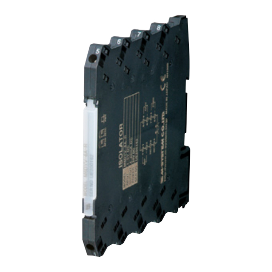
Euro Terminal Ultra-Slim Signal Conditioners M6D Series
FUNCTION MODULE
(PC programmable)
Functions & Features
• Single input filter and function module
• 12 types of functions are PC programmable
• 5.9-mm wide ultra-slim design
• Low profile allows the M6D module mounted in a 120-mm
deep panel
• High-density mounting
• Power and status indicator LEDs
• UL approval
5.9 (.23)
94
(3.70)
102
(4.02)
mm (inch)
MODEL: M6DXF1–[1][2]–R[3]
ORDERING INFORMATION
• Code number: M6DXF1-[1][2]-R[3]
Specify a code from below for each [1] through [3].
(e.g. M6DXF1-Z1Z1-R/UL)
• Input range (e.g. 4 – 20 mA DC)
• Output range (e.g. 4 – 20 mA DC)
[1] INPUT
Current
Z1: Range 0 – 50 mA DC (Input resistance 24.9 Ω)
Voltage
S1: Range -1000 – +1000 mV DC (Input resistance 1 MΩ min.)
S2: Range -10 – +10 V DC (Input resistance 1 MΩ min.)
(Configurator software is used to change the input type and
precise range.)
[2] OUTPUT
Current
Z1: Range 0 – 20 mA DC
Voltage
V2: Range -10 – +10 V DC
SEN TRONIC
AG
Produkte, Support und Service
V3: Range -5 – +5 V DC
(Configurator software is used to change output over the
described range of the selected suffix code.
For changing between suffix codes, set the Output Range
Selector on the side of unit before software adjustment.)
POWER INPUT
DC Power
R: 24 V DC
(Operational voltage range 24 V ±10 %, ripple 10 %p-p max.)
[3] OPTIONS
STANDARDS & APPROVALS
blank: CE marking
/UL: UL approval (CE marking)
FUNCTIONS
PC Configurator Software is used to program the function.
Filter, linearization and limiter functions can be combined.
• Filter / Lag
· Moving average output
· Dead time computing
· Delay buffer (first order lag)
· Lead time computing
· Ramp buffer
• Linearization
· User's table linearization
· Inverted output
· Square root extraction (orifice, venturi)
2
· X
(Palmer-Bowlus flume, Parshall flume)
5/2
· X
(triangular or v-notch weir)
3/2
· X
(rectangular weir)
• Limiter
· High / Low limit
Factory default function setting
Filter: Moving average
(H = 0.1, N = 1, U = 0, L = 0)
Linearization: None
Limiter: Low limit = -2 %, High limit = 102 %
RELATED PRODUCTS
• PC configurator software (model: M6CFG)
Downloadable at M-System's web site.
A dedicated cable is required to connect the module to the
PC. Please refer to the internet software download site or
the users manual for the PC configurator for applicable
cable types.
Rugghölzli 2
Tel. +41 (0)56 222 38 18
CH - 5453 Busslingen
Fax +41 (0)56 222 10 12
MODEL: M6DXF1
mailbox@sentronic.com
www.sentronic.com
Advertisement
Table of Contents

Related Manuals for M-system M6DXF1


Summary of Contents for M-system M6DXF1
- Page 1 · Square root extraction (orifice, venturi) ORDERING INFORMATION · X (Palmer-Bowlus flume, Parshall flume) · X (triangular or v-notch weir) • Code number: M6DXF1-[1][2]-R[3] · X (rectangular weir) Specify a code from below for each [1] through [3]. • Limiter (e.g. M6DXF1-Z1Z1-R/UL) ·...
-
Page 2: General Specifications
MODEL: M6DXF1 Load resistance: Output drive 11 V max. GENERAL SPECIFICATIONS (e.g. 4 – 20 mA: 550 Ω [11 V/20 mA]) Connection If not specified, the output range is 4 – 20 mA DC. Input and output: Euro terminal (torque 0.3 N·m) •... -
Page 3: Standards And Approvals
MODEL: M6DXF1 0.01 % = 0.05 % • Output accuracy = Max. Output Range (10 V) / Span (4 V) × 0.04 % = 0.1 % Accuracy= ±0.15 % STANDARDS & APPROVALS CE conformity: EMC Directive (2004/108/EC) EN 61000-6-4 (EMI) - Page 4 MODEL: M6DXF1 DIMENSIONS unit: mm (inch) WIRE INSERTION ANGLE: approx. 7° 8–M3 EURO TERMINAL DIN RAIL HOOK DIN RAIL 35mm wide SCREWDRIVER [0.5 (.02)] INSERTION ANGLE : approx. 40° 5.9 (.23) 102 (4.02) • When mounting, no extra space is needed between units.
- Page 5 MODEL: M6DXF1 FUNCTIONS INPUT MOVING AVERAGE OUTPUT The module samples input signals every H seconds and, excluding U numbers of highest-value samples and L numbers of lowest-value samples, outputs proportionally to the average of the rest [N (U + L)] of sampled data. When...
- Page 6 MODEL: M6DXF1 LEAD-TIME COMPUTING The module operates a lead-time equation. Step input with lead-time constant • (s) = (1 + Ts) X INPUT where : Input : Output Parameters T: Lead-time constant (0.5000 to 100.0000 seconds) OUTPUT RAMP BUFFER Step input with rate-of-change limits •...
-
Page 7: Function Module
M6DXF1 INSTRUCTION MANUAL FUNCTION MODULE M6DXF1 MODEL (PC programmable) • Do not bind these cables together with those in which BEFORE USE ..noises are present. Do not install them in the same duct. Thank you for choosing M-System. Before use, please check ■ AND ..contents of the package you received as outlined below. The unit is designed to function as soon as power is sup-... -
Page 8: Terminal Connections
M6DXF1 TERMINAL CONNECTIONS Connect the unit as in the diagram below or refer to the connection diagram on the side of the unit. ■ EXTERNAL DIMENSIONS unit: mm (inch) WIRE INSERTION ANGLE: approx. 7° 8–M3 EURO TERMINAL DIN RAIL HOOK DIN RAIL 35mm wide SCREWDRIVER [0.5 (.02)] INSERTION ANGLE : approx. 40° 5.9 (.23) 102 (4.02) • When mounting, no extra space is needed between units. -
Page 9: External Views
M6DXF1 EXTERNAL VIEWS ■ FRONT VIEW (with the cover open) ■ SIDE VIEW Power LED Status Indicator LED Output Range Selectors Configurator Jack OUTPUT RANGING CHECKING The internal DIP switch setting is required to select output 1) Terminal wiring: Check that all cables are correctly con- types before setting a precise output range using PC Con- nected according to the connection diagram. figurator Software (model: M6CFG). 2) Check DIP switch setting. For detailed information on the PC configuration, refer to 3) Power input voltage: Check voltage across the terminal the M6CFG users manual. - Page 10 M6DXF1 FUNCTIONS ■ MOVING AVERAGE OUTPUT The module samples input signals every H seconds and, INPUT excluding U numbers of highest-value samples and L numbers of lowest-value samples, outputs proportionally to the average of the rest [N × (U + L)] of sampled data. When a new input is sampled after another H seconds, it gives up the oldest sample and calculates a new average including the latest sample and outputs proportionally. N numbers When the number of samples to be calculated equals 0 or N numbers less, it outputs an error. average OUTPUT Parameters H : Sampling cycle (0.1000 to 100.0000 seconds) N : Number of samples to be calculated (1 to 128) U : Number of highest-value samples to be cut off (0 to 127) L : Number of lowest-value samples to be cut off (0 to 127) ■ DEAD-TIME COMPUTING The module does not respond to an input signal for a pre- •...
-
Page 11: Maintenance
M6DXF1 ■ LEAD-TIME COMPUTING ■ INVERTED OUTPUT The module operates a lead-time equation. The output is inversely proportional to the input. (s) = (1 + Ts) X (s) = 100 – X where X : Input where X : Input (%) : Output : Output (%) Parameters T : Lead-time constant (0.5000 to 100.0000 seconds) ■ SQUARE ROOT EXTRACTION (orifice, venturi) The output is inversely proportional to the input. • Step input with lead-time constant ___ = 10 √ X...
Need help?
Do you have a question about the M6DXF1 and is the answer not in the manual?
Questions and answers