Table of Contents
Advertisement
Quick Links
Thank you for purchasing a Panasonic product.
This document explains how to install the water leak sensor properly.
For details about how to use the system, refer to the User's Guide
(page 20).
Please read this document before using the unit and save it for future
reference.
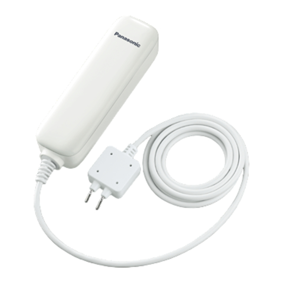
Home Network System
KX-HNS103AZ
Model No.
Installation Guide
Water Leak Sensor
Advertisement
Table of Contents

Related Manuals for Panasonic KX-HNS103AZ


Summary of Contents for Panasonic KX-HNS103AZ
- Page 1 Home Network System Water Leak Sensor KX-HNS103AZ Model No. Thank you for purchasing a Panasonic product. This document explains how to install the water leak sensor properly. For details about how to use the system, refer to the User’s Guide (page 20).
-
Page 2: Table Of Contents
Table of Contents Introduction Accessory information ....3 Important Information About this system ......4 For your safety ......4 Important safety instructions ..5 For best performance ....5 Other information .......6 Setup Part names and functions ..8 LED indicator ......8 Setup overview ......8 Inserting the battery ....9 Registering the sensor ....9 Confirming the usage area ..10... -
Page 3: Accessory Information
Introduction Accessory information Supplied accessories Accessory item/Part number Quantity Battery Wall mounting adaptors Wall mounting screws (25 mm) When replacing the battery, see “Power source” of “Specifications”, page 21 for battery information. 1 adaptor for the main unit 1 adaptor for the probe unit 2 screws for the main unit and 1 screw for the probe unit Other information R Design and specifications are subject to change without notice. -
Page 4: Important Information
Keep the main Panasonic will not be held unit upright at all times. responsible in the event that R Do not allow the probe unit to make... -
Page 5: Important Safety Instructions
Keep it in a cool, dark area. The hub and other compatible R Do not replace a battery with wet Panasonic devices use radio waves to hands. communicate with each other. R Keep out of the reach of small R For maximum coverage and children. -
Page 6: Other Information
Important Information between the product and hub in an indoor environment. Other information – away from electronic appliances such as TVs, radios, personal CAUTION: Risk of explosion if battery computers, wireless devices, or is replaced by an incorrect type. other phones. Dispose of used batteries according to –... - Page 7 Important Information these items, please contact your local authorities or dealer and ask for the correct method of disposal. Note for the battery removal procedure Refer to “Inserting the battery” on page 9.
-
Page 8: Setup
Setup off by pressing M N again as soon as possible, otherwise battery life may Part names and be reduced. functions Indicator Status Green, lit No water detected Red, lit Water detected Red, Sensor is out of range blinking of the hub Green, Registration mode blinking... -
Page 9: Inserting The Battery
Setup Inserting the battery Registering the sensor R USE ONLY a CR2 Lithium battery. R Confirm the polarities ( This procedure is not required for Remove the main unit cover. devices that were included as part of R Lift from the indented area (A) a bundle. -
Page 10: Confirming The Usage Area
Setup group them by location. For more information, refer to the User’s Guide (page 20). Confirming the usage area Wireless communication range The wireless communication range of each device in the system from the hub is approximately 50 m indoors and approximately 300 m outdoors. -
Page 11: Installation
R The sensor is not designed to be used in situations that require high reliability. We do not recommend use of the sensor in these situations. R Panasonic takes no responsibility for any injury or damage caused by the use of this product. - Page 12 Setup R Touching the metal probes with your hand may cause a water leak to be detected. This is not a defect. R Install the probe unit so that the metal probes are horizontal. A water leak can only be detected if water touches both of the metal probes; if water touches only one of the probes, a water leak will not be detected.
- Page 13 Setup R Install the main unit 1 m or higher above the floor. The main unit is not waterproof; if it becomes wet, the sensor may become damaged and water leaks will not be detected properly.
- Page 14 Setup Securing with the wall mounting adaptors Use screws to attach the wall mounting adaptors to the wall. n Main unit Screws 75 mm n Probe unit Screw Note: R To install the probe unit on a floor, see page 18. In this case, you will not use the probe unit’s wall mounting adaptor.
- Page 15 Setup R Use the following template below when determining the location of the screw holes. 75 mm...
- Page 16 Setup Remove the backing from the double-sided tape, insert the main unit and the probe unit into the wall mounting adaptors, and then press firmly on each unit to ensure solid adhesion to the installation surface. Double-sided tape...
- Page 17 Setup Securing with double-sided tape only Note: R Make sure any surfaces that will make contact with the double-sided tape are clean and dry before applying the tape. When attaching the double-sided tape to concrete or bricks, if the surface of the concrete or bricks is wet, make sure to completely dry the surface before attaching the double-sided tape.
- Page 18 Setup Installing the probe unit on a floor When installing the probe unit on a floor, use the double-sided tape to attach the probe unit directly to the floor. Note: R If the probe unit is inserted into the wall mounting adaptor and attached to a floor, the probes will be too far from the floor and therefore water leaks can only be detected after the leaked water has become deep enough to touch the probes.
- Page 19 Setup Removing from the wall n Removing from the wall mounting adaptors Insert a flat screwdriver into the notches on the wall mounting adaptors, and carefully pry away the main unit and probe unit. Remove the screws that secure the wall mounting adaptors to the wall. n Removing when secured with double-sided tape only Tie a piece of thread to two sticks, screwdrivers, etc.
-
Page 20: Appendix
You can use the app to arm and disarm the alarm system, confirm the current status of the sensor, and view a log of previous events. www.panasonic.net/pcc/support/tel/ – Sensor integration homenetwork/manual/ You can configure the sensor to trigger other system events, such as camera recording, turning on an electric device (such as a lamp), etc. -
Page 21: Specifications
Appendix Specifications R Standards DECT (Digital Enhanced Cordless Telecommunications) R Frequency range DECT: 1.88 GHz – 1.90 GHz R RF transmission power Approx: 10 mW (average power per channel) R Power source Lithium battery CR2 (1 ´ 3.0 V, 850 mAh) R Operating conditions 0 °C –... -
Page 22: Warranty (For New Zealand)
6) Damage to the product caused by accident, misuse or Act of God. 7) Repairs when the product has been dismantled, repaired, modified or serviced by other than a Panasonic Authorised Dealer authorised to service that type of product. IF YOUR PANASONIC PRODUCT FAILS WITHIN THE... - Page 23 Notes...
- Page 24 Sales Department: 18 Sir Woolf Fisher Drive, Highbrook, East Tamaki, Auckland, New Zealand Phone: (09) 272 0100 Fax: (09) 272 0137 1-62, 4-chome, Minoshima, Hakata-ku, Fukuoka 812-8531, Japan © Panasonic System Networks Co., Ltd. 2015 *PNQX7357ZA* *PNQX7357ZA* PNQX7357ZA CC0715WK0 (E)
Need help?
Do you have a question about the KX-HNS103AZ and is the answer not in the manual?
Questions and answers