Table of Contents

Subscribe to Our Youtube Channel
Related Manuals for Go Power GP-TS-30


Summary of Contents for Go Power GP-TS-30
- Page 1 30 Amp Transfer Switch User Manual GP-TS-30 © 2020 Go Power! Worldwide Technical Support and Product Information gpelectric.com Go Power! 201-710 Redbrick Street Victoria, BC, V8T 5J3 Tel: 1.866.247.6527 MOBI_MAN_GP-TS-30-RevE...
- Page 2 Congratulations on purchasing your Go Power! 30-amp Transfer Switch Record the unit’s model and serial number below. It is much easier and quicker to record this information now at the pre-installation stage. Model Number: Serial Number: Date of Install: Battery Bank Information:...
-
Page 3: Table Of Contents
CONTENTS INTRODUCTION..........................4 INSTALLATION..........................4 OPERATIONAL TESTING......................7 TROUBLESHOOTING........................8 HI-POT TESTING........................9 GENERATOR NOTE.........................10 MEDICAL APPLIANCES......................10 8. CAUTION............................10 WARNINGS..........................10 10. WARRANTY..........................11 gpelectric.com | [page 3]... -
Page 4: Introduction
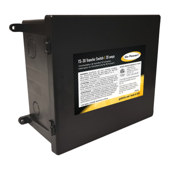
1. INTRODUCTION The Go Power! 30-amp Transfer Switch (TS-30) provides automatic power switching between two separate 120 volt AC input sources, including power cords, onboard generators, or onboard inverters. The TS-30 will sense the presence of available power supplies and automatically select the proper one. - Page 5 2. INSTALLATION 2.5.1 TIMING DELAY The transfer switch will have a delay as it switches from one source to another. The delay can be eliminated by placing a jumper across two pins on the timing board within the unit. The hybrid system involves pulling a line from the main distribution panel through to a second transfer switch to only power circuits in a coach.
- Page 6 INSTALLATION Diagram 1 – Typical Generator Power Cord Connection 2.5.2 INSTALLATION BETWEEN INVERTER AND ALTERNATING SOURCE (CONFIGURATION C) 1. For installation between inverter (default) and another power supply (dominant), such as the output from a prior power cord/ generator transfer switch. These connections will allow any other supply to dominate the inverter, and the inverter output will pass through the normally closed contacts of the switch.
-
Page 7: Operational Testing
The diagrams show where the Inverter/Charger is installed and how the mobile power system can be integrated with a Go Power! RV Solar Kit (sold separately by Go Power; please contact us directly.) 1. Plug in the power cord. If the main panel circuit breakers are switched on, RV load should operate normally. Unplug the power cord. -
Page 8: Troubleshooting
4. TROUBLESHOOTING TROUBLESHOOTING 4.1 LOW VOLTAGE Low voltage is harmful to most appliances. Contactor-based transfer switches are also affected by low voltage; if the voltage level drops far enough the contactor points will “chatter”. Sustained contact chattering can cause transfer switch damage. Switches that have been damaged by chattering need to be returned to the factory for replacement. -
Page 9: Hi-Pot Testing
5. HI-POT TESTING 4.5 TESTING FOR PROPER CIRCUIT BOARD OPERATION 1. Disconnect all AC power from the RV and make sure the generator is OFF. 2. Remove the cover from the ATS sliding a screwdriver blade under the edge of the cover and pry off. 3. -
Page 10: Generator Note
MEDICAL APPLICANCES Go Power! will not knowingly sell a Go Power! Automatic Transfer Switch for any life-support application. It is strongly recommended that you do not operate any life support equipment from a transfer switch. If the switch should malfunction, or fail to operate due to other external conditions, it is possible that all connected appliances, including any life support equipment, will also shut down, resulting in a risk of medical complications and potential loss of life. -
Page 11: Warranty
United States and Canada from defects in materials or workmanship under normal use for two years from date of retail purchase and will repair or replace any Go Power!™ Transfer Switch under warranty found to be defective free of charge. - Page 12 © 2020 Go Power! Worldwide Technical Support and Product Information gpelectric.com Go Power! 201-710 Redbrick Street Victoria, BC, V8T 5J3 Tel: 1.866.247.6527 MOBI_MAN_GP-TS-30-RevE...
Need help?
Do you have a question about the GP-TS-30 and is the answer not in the manual?
Questions and answers