Advertisement
Quick Links
Installation Instructions:
Remove the four (4) 6-32 assembly screws.
Separate the housing and electronics assembly. Unplug
electronic assembly from the faceplate and housing.
Set the electronic assembly aside, carefully.
Remove the four (4) 8-32 mounting nuts from the mounting rods.
Separate the faceplate and housing. Discard the shipping spacers
located between the faceplate and housing if there are any. Hold the
faceplate over the partition opening. Carefully center the faceplate and
align the lettering horizontally. Masking tape can be used to temporarily
hold the faceplate to the outside of the partition.
On the inside of the partition mount the housing over the four (4)
8-32 mounting rods. Be certain to position the housing so that the
threaded hole is positioned properly. If using tubing, orient the hole in
the direction which the tubing is to exit (left, right, top, and bottom). If
tubing is not being used, place the plugged hole at the bottom.
Recommended cables for wiring :
For power connections use West Penn wire #221. This is a
stranded single pair 22 awg, Plenecon -II jacket Rohs cable. Keep
Mic/spk and power cable bundles away from other power cable.
For power connection, route the one pair cable (with the connector
on one end). From the inside unit to the location of the PS-1 power
supply. Connect the conductors to the power supply (RED to +ve,
BLACK to -ve). Plug the connector to its mate from the printed
circuit board. Connect 4 – pin polarized connectors and reassemble
units
3
Place the housing so that the threaded hole can be positioned
properly. If using tubing, orient the hole in the direction in which the
tubing is to exit as shown in the drawing.
Be certain to position the housing so that the threaded hole can
be positioned properly. If using tubing, orient the hole in the
direction which tubing is to exit.
HOW TO USE THE TALK-THRU COMMUNICATOR...
1. With power switch off, turn Talk and Listen controls
completely counter clockwise.
2. Turn on the unit by switching the Power ON/OFF switch to its
upper position. At this position, the unit is at the auto mute
mode.
3. Adjust the TALK volume control until the attendant is clearly heard
by the person outside the window when the attendant is speaking 2"
to 4" from the gooseneck microphone at a normal speaking level. The
green LED should go on when the attendant starts talking and go off
when the attendant stops talking. If the green LED stays lit
constantly, it indicates either the TALK volume setting or the
ambient noise is too high.
4. Adjust the LISTEN control until the person outside the window is
clearly heard when speaking at a normal level.
4
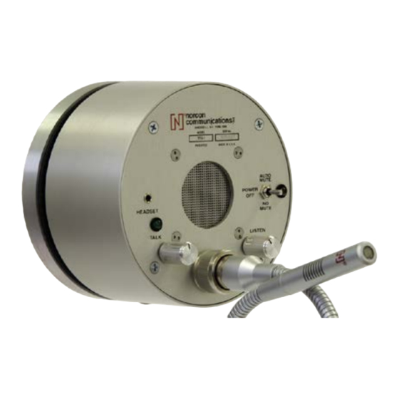
TTU® -1X Series 2-Way Talk-Thru Electronic
Communication System.
A voice communications system for High-Security and Isolation
Booth Situations. In today's security conscious environment,
isolation booths are often the ideal recourse to protect your
employees. But does it facilitate and help maintain your very
important public image? Not if clerks and customers have to yell and
repeat themselves to be heard or understood.
The Patented TTU® -1X Talk-Thru Communicator is a 2-way,
hands-free audio system that provides high-quality personal
communication between people separated by security or isolation
barriers. It is the most widely used system of its type in the U.S., and
the world.
FEATURES
•
Clear 2-way hands-free voice communication.
•
Quality electronic design and engineering.
•
Avoid raising your voice, repetition & misunderstanding.
•
XLR removable mic for your convenience.
•
Simple, one-person installation.
•
Rugged, tamper-resistant materials. Anodized aluminum
•
Self-powered with fast rechargeable battery option.
•
Bullet-resistant option (UL level 3).
•
Units available for ADA applications.
•
Headset jack equipped on all models. Headset can be ordered
separately.
•
Export models available
1
OPERATION HINTS
:
1. Increasing the talk volume control allows the attendant to
speak further away from the microphone as well as increasing
the talk channel volume. The optimum distance from the
microphone should be maintained at approximately 2"-4" or
conversations not directed to customers may be heard outside
the booth. Watch the green LED above the TALK volume
control, it should be ON only when talking into the gooseneck
microphone and off when not talking to the microphone.
2.
Installing a headset into the Headset jack will allow
communications from the headset and disconnect the speaker
and the gooseneck microphone.
3.
The unit will decrease the incoming volume level by
approximately 70% some 30 seconds after the attendant stops
speaking into the microphone. The purpose of this feature is to
decrease the amount of extraneous noise entering the booth.
Normal volume level is restored when the attendant speaks
into the microphone. The muting function can be defeated by
switching the POWER SWITCH to the NO MUTE position.
5
HOW IT WORKS ...
The Norcon TTU® system permits hands-free, 2-way
communication between the booth attendant and the customer.
Unique circuitry facilitates ongoing, clear, 2-way conversation at all
times – as if the two parties were together in the same room. The
TTU®-1X Talk-Thru Communicator now incorporates circuitry to
automatically attenuate the outside channel. If the gooseneck
microphone is not used for a period of 30 seconds, the outside
channel volume will be reduced approximately 70%. Normal operation
is restored as soon as the attendant speaks into the gooseneck
microphone. The automatic volume attenuation circuit prevents
outside noise from bothering the attendant.
The TTU® -1X provides clear communication even in
environments with high ambient noise by shaping the sound for
maximum intelligibility. Its compression circuitry decreases loud,
annoying sounds.
HOW TO INSTALL ...
Installation of the TTU® -1X is a very simple, one-person operation.
All that's needed is a 3" to 4" diameter cutout in the barrier. Four
fasteners and two rubber gaskets for mounting are supplied. The front
face and housing are easily mounted on opposite sides of the barrier
using the fasteners. The rubber gaskets prevent slippage and protects
the barrier surface. The electronic section is then inserted into the
housing and fastened in place.
2
SPECIFICATIONS:
MECHANICAL:
•
Outside faceplate: Aluminum, anodized finish, tamper-resistant.
•
Control housing (inside): Machined aluminum, anodized finish,
tamper-resistant.
•
Size: Outside faceplate 5" Dia. x ½" D. Inside control housing:
5" Dia. x 2-1/2" D (TTU®-1 AX) (TTU®-1 AX)
5" Dia. x 3-1/2" D (TTU®-1 D X) (TTU®-1 ABX)
•
Weight: ~ 5 LB.
•
Mounting: Partition hole 3 to 4" Dia. (3-1/2" recommended)
Specify barrier thickness when ordering. Norcon will adjust
the length of the mounting rods to meet your need.
Panel Controls: LISTEN volume, TALK volume, POWER On/Off,
AUTO MUTE On/Off.
ELECTRONIC:
•
Audio frequency response: Selectively shaped for maximum voice
intelligibility.
•
Audio power: 2 watts per amplifier.
•
Distortion: Less than 2%.
•
Listen mode: 20dB compression.
•
Microphone: Electret.
•
Power Supply Adapter: Input 90-240V AC, 60 Hz. Output 15V
DC, 1A. UL, (Canada and US) CE, level VI.
Specifications are subject to change without notice.
6
TTU-1A XLR P.1.
Advertisement

Related Manuals for Norcon Communications TTU-1X Series


Summary of Contents for Norcon Communications TTU-1X Series
- Page 1 HOW IT WORKS … TTU® -1X Series 2-Way Talk-Thru Electronic The Norcon TTU® system permits hands-free, 2-way Communication System. communication between the booth attendant and the customer. A voice communications system for High-Security and Isolation Unique circuitry facilitates ongoing, clear, 2-way conversation at all Booth Situations.
- Page 2 TROUBLESHOOTING: You may occasionally encounter a problem with your TTU® system. If this happens, refer to the trouble shooting list. If additional help is needed, please contact us. No sound at all • Is the power cable properly connected to power supply and the power supply plugged into a working outlet? The power cable red wire should be connected to (+) and black wire connected to (-) the power supply.