Table of Contents
Advertisement
Quick Links
Operation Manual
Tone Generator & Amplifier Probe
Do not connect Tone Generator unit to live AC power line (220/110 VAC) or
DC power line which exceed 120 VDC.
IMPORTANT
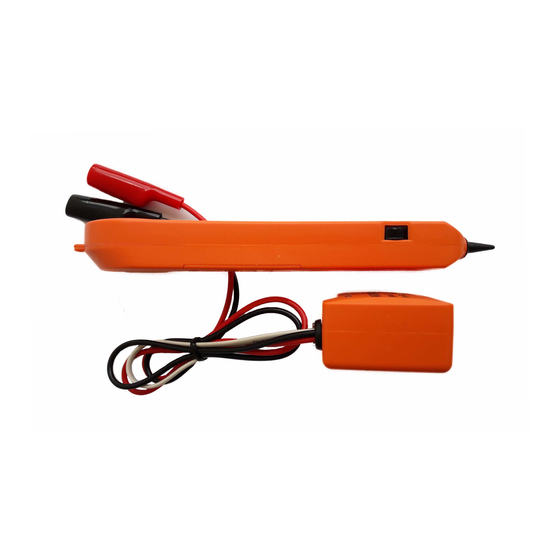
Tone Generator & Amplifier Probe must be installed 9V. battery before operation
Volume
control
Audio jack
Figure 1 Amplifier Probe
Amplifier Probe
Features
• Designed to identify and trace wires without necessary damaging the
insulation.
• Works with any Tone Generator.
• Volume control for sensitivity adjusting to suit working environment.
• Recessed ON/OFF button switch to prevent battery drain while standby.
• Power supply by 9V battery with an average operating life of 100 hours.
• Audio earphone jack for operating in noisy environment such as server
room,etc.
• LED for illustration of signal strength of tone receiving.
LED
ON/OFF button
Black
Modular plug
LED
Figure 2 Tone Generator
Red
3-position
toggle
switch
Page 1
Advertisement
Table of Contents

Related Manuals for Pantong Metodo2

Summary of Contents for Pantong Metodo2
- Page 1 Operation Manual Tone Generator & Amplifier Probe Do not connect Tone Generator unit to live AC power line (220/110 VAC) or DC power line which exceed 120 VDC. IMPORTANT Tone Generator & Amplifier Probe must be installed 9V. battery before operation Black Modular plug Volume...
- Page 2 Tone Generator Features • Red and black alligator clip test leads for connecting in sending tone. • A 3-position toggle switch for selecting mode of operation, a 3-colored LED for indicating line polarity, continuity, ring-in voltage, etc . • A tone selector switch, located on PCB inside the case for selecting either a single solid tone, or dual alternating tone.
- Page 3 the coppers (4/8 wires for RJ11/RJ45 ) one end, and terminating modular plug the other end. OPTIONAL USE METHOD (PAIRED) : Connect one clip to a wire and connect the other clip to the other wire of pair(See figure 4). This method can further verify if tracing pair is the target by momentarily shorting the pair at trace end and found that the tone is stop.
- Page 4 IDENTIFYING PHONE LINES (SWITCH TO “OFF” THEN “CONT”) 1. Dial the line to be identified. 2. While the line is being ring, connect the RED clip to a wire and the BLACK clip to the other wire of pair. 3. In the “OFF” position, the indicator LED will blinking “GREEN” or “RED” if connected to the target pair.
Need help?
Do you have a question about the Metodo2 and is the answer not in the manual?
Questions and answers