Table of Contents
Advertisement
Quick Links
Operation Manual
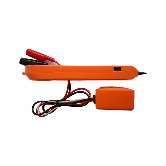
Tone Generator & Amplifier Probe
Do not connect Tone Generator unit to live AC power line (220/110 VAC) , or
DC power line which exceed 110 VDC.
IMPORTANT
Tone Generator & Amplifier Probe must be installed 9V. battery before operation
Volume
control
Audio jack
Figure 1 Amplifier Probe
Amplifier Probe
Features
• The Amplifier Probe is designed to identify and trace wires or cables within
a group without damaging the insulation
• Works with any Tone Generator to idenlify wires.
• Volume control for increased sensitivity and adjustable to suit work
environment.
• Recessed ON/OFF button prevents battery drain.
• Power supply is in any 9V battery with a life of approximately 100 hours.
• Audio jack for headphone to operate in noisy environment.
• LED indicator for signal strength of tone receive
LED
ON/OFF button
Black
Modular plug
LED
Figure 2 Tone Generator
Red
3-position
toggle
switch
Page 1
Advertisement
Table of Contents

Summary of Contents for Pantong METODO2
- Page 1 Operation Manual Tone Generator & Amplifier Probe Do not connect Tone Generator unit to live AC power line (220/110 VAC) , or DC power line which exceed 110 VDC. IMPORTANT Tone Generator & Amplifier Probe must be installed 9V. battery before operation Black Modular plug Volume...
- Page 2 Tone Generator Features • Red and black test leads are provided, and also a standard RJ11 modular plug • A 3-position toggle switch controls the modes of operation plus a 3-colored LED Light Emitting Diode is provided for line polarity, continuity and voltage testing.
- Page 3 OPTIONAL USE METHOD (PAIRED) : Connect one test lead to a wire and connect the other test lead to the other wire of pair(See figure 4). This method can further verify if tracing pair is the target by momentarily shorting the pair at trace end and found the tone is cancelled.
- Page 4 3. In the “OFF” position, the indicator LED will blinking “GREEN” or “RED” when the test leads are connected to the target pair. 4. Re-confirm by switch to “CONT”, that will terminate the call on the target line. TESTING CONTINUITY(SWITCH TO “CONT”) 1.

Need help?
Do you have a question about the METODO2 and is the answer not in the manual?
Questions and answers