Table of Contents
Advertisement
Quick Links
Advertisement
Table of Contents
Troubleshooting

Related Manuals for AQ Elteknik D72

Summary of Contents for AQ Elteknik D72
- Page 1 Ultrasound Controller D72 DP72 D128 G72 Manual AQ Elteknik AB...
- Page 3 Ultrasound Controller D72 DP72 D128 G72 version RevE DP72 version RevE D128 version RevA version RevA Manual version 4.52 Software version 4.5x Gsd file version 3.2 (for DP72) January 2014 AQ Elteknik AB AQ Elteknik AB Ultrasound Controller Manual...
-
Page 4: Table Of Contents
Manufacturer Information ....................................5 Certificate of Quality and Function ..................................5 Introduction ..........................................6 Ultrasound Controller ......................................6 Installing the Ultrasound Controller D72................................6 Installing the Ultrasound Controller DP72 ................................7 Installing the Ultrasound Controller D128................................7 Navigating the menu system ....................................8 Sensor MODE and the start-screen ................................... -
Page 5: Manufacturer Information
Under no circumstances shall AQ Elteknik be held responsible for any loss or indirect damage howsoever caused. The contents of this document are provided as it is. AQ Elteknik AB reserves the right to revise this document or withdraw it at any time without prior notice. -
Page 6: Introduction
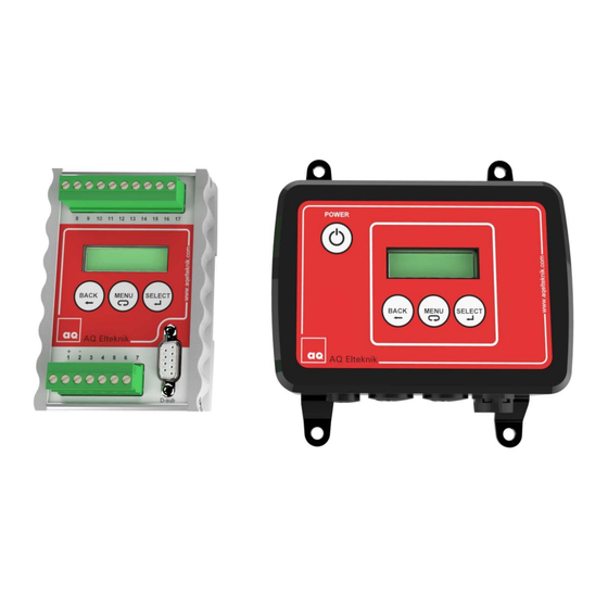
Four single gel-levels can be measured with one Ultrasound Controller. Installing the Ultrasound Controller D72 and G72 The Ultrasound Controller D72 should be protected from dust and water. It is made to be attached to a DIN-rail, to which it D72, G72... -
Page 7: Installing The Ultrasound Controller Dp72
A person with the required knowledge Relay 4 should perform the installation. mA output MINUS + 4-20mA output A + 4-20mA output B Enclosure Gasket Bottom plate Screws Terminals Dummy coverings Cable glands (small and big) Pressure compensation element AQ Elteknik AB Ultrasound Controller Manual... -
Page 8: Navigating The Menu System
3. Navigating the menu system Toggle between Go back to previous Scroll through the menu Select a menu standby and menu-level power-on. Scroll through a Confirm the Cancel a list of parameter- selection of a Selected values parameter-value Switches (D128 only) operation Keep MENU button pressed to scroll continuous through parameter values. -
Page 9: Air Sensor Mode
(and label) is facing up. If instead low bubble sensitivity is desirable rotate the Air Sensor so that the cable connector (and label) is facing down. This makes the Air Sensor less sensitive for bubbles at the top of the tube. AQ Elteknik AB Ultrasound Controller Manual... -
Page 10: Setting Lowest Possible Sensitivity For Bubbles
Setting lowest possible sensitivity for bubbles If mounted horizontally rotate the Air Sensor so that the cable connector is facing down. The FILTER setting determines the delay (response time) for detecting air. Consider what is the longest acceptable delay for detecting air that can be accepted and set FILTER accordingly: delay 0,3s or longer (don’t set it to integrate). -
Page 11: Settings
Select SET RELAY to set how the relays should act. There are four relays each with one normally open contact (at power off and when sensor is not connected the relay is open). Each relay can be set independently. Choose between Closed with air or closed with liquid and choose AQ Elteknik AB Ultrasound Controller Manual... -
Page 12: Air Sensor Start-Screen
between Air Sensor 1 and Air Sensor 2. The duration of air being indicated is minimum 0,5 second even if the bubble is detected much shorter time (to make sure the indication of air is registered). Select SET mA output to set the assignment of the mA-outputs. There are two mA-outputs: A and B. -
Page 13: Advanced Settings
VLthld depends on the type of Air Sensor. Air Sensors with diameter < 14mm can not use very low sensitivity. err 3 is displayed if VLthld becomes too low for reliable measurements, see troubleshooting. AQ Elteknik AB Ultrasound Controller Manual... -
Page 14: Help
Select AUXILIARY DATA to show unprocessed data from the Air Sensor. It can be used for troubleshooting when contacting AQ Elteknik AB. HELP Select HELP to show information about connecting the Ultrasound Controller. Sound velocity in the Air Sensor When there are two liquids with significant different sound velocity in the Air Sensor and these liquids are not well mixed, there can be a false indication of air. -
Page 15: Air Sensor Troubleshooting
Calibration of LIQUID has been done with air or liquid having lots of bubbles or particles attenuating the sound. Wrong settings of Air Sensor Type or Diameter. Wrong connected Air Sensor. A faulty Air Sensor AQ Elteknik AB Ultrasound Controller Manual... -
Page 16: Level Switch Mode
5. Level Switch Mode In Level Switch Mode the Level Switch measures a single level from the side of the container. It measures the presence or no presence of liquid behind the container (or pipe) wall. The Level Switch senses through the wall AND no hole is needed. Four Level Switches can be connected to one Ultrasound Controller. -
Page 17: Level Switch Type And Technique
The WR-technique measures very small signal changes and is sensitive to small movements of the Level Switch. The Level Switch must therefore preferably be glued. The WR-technique can also be sensitive to liquid drops remaining on the inside of the wall and sensitive to temperature changes. AQ Elteknik AB Ultrasound Controller Manual... -
Page 18: Mounting The Level Switch
The advantage of the WR-technique is it is independent of liquid properties and that there is no need for a reflecting surface. Mounting the Level Switch How to mount the Level Switch on the container is described in Level Switch manual. Level Switch start-screen Lev Sw When power is applied, the Level Switch start-screen is displayed showing... -
Page 19: Container With Jacket
0 and 70 should be shown. If by pressing on the inner side of the Level Switch with your finger this value increases then the Level Switch is working. A Level Switch wrongly connected or unconnected shows a value higher than 100. AQ Elteknik AB Ultrasound Controller Manual... -
Page 20: Advanced Settings
ADVANCED SETTINGS Select Set sensor MODE to set either Air Sensor mode or Level Switch mode or Level Sensor mode. It determines which sensor can be connected. Changing sensor mode does not alter any settings or calibrations. Select SIMULATE to simulate detection of air or liquid. Press SELECT button to toggle between simulation of Air and Liq. -
Page 21: Level Switch Troubleshooting
Also any unscreened part of the cable between the Level Switch and Ultrasound Controller should be short. If ex-barriers are used, Ex-barriershields must be used especially if there is more than one Ultrasound Controller. AQ Elteknik AB Ultrasound Controller Manual... -
Page 22: Level Sensor Mode
6. Level Sensor Mode In Level Sensor mode a level sensor is attached at the bottom of the container and measures the continuous liquid level. The level sensor is attached outside the container and senses through the bottom (no hole is needed). A velocity sensor can also be attached, measuring sound velocity. -
Page 23: Connecting The Level Sensor
Ultrasound Controller and be active measuring while it is being glued so that it can be adjusted for loudest echo. Loudest echo may not be at exactly AQ Elteknik AB Ultrasound Controller Manual... -
Page 24: Mounting The Velocity Sensor
horizontal position. The deviation from horizontal bottom for stainless steel must be less than 10˚. Fill the container above half and place the level sensor with silicone in a position expected to be good and calibrate liquid. If there is no error go to Level Sensor measured data. The echo strength is shown in dB. -
Page 25: Calibration
Select Velocity Sensor x calibrated data to show calibrated velocity m/s, calibrated signal strength dB, calibrated frequency MHz and calibrated threshold for detecting liquid %. Calibrated threshold must not be too high, less than 50% is good. AQ Elteknik AB Ultrasound Controller Manual... -
Page 26: Advanced Settings
ADVANCED SETTINGS Select Set sensor MODE to set either Air Sensor mode, Level Switch mode or Level Sensor mode. It determines which sensor can be connected. Changing sensor mode does not alter any settings or calibrations. Select RESTORE settings and calibrations to restore all settings and calibrations to factory-settings. - Page 27 The liquid is rotating and the centrifugal force makes the surface parabolic thereby reflecting echo in wrong direction. – Try finding better position for the level sensor, maybe in the middle of the container. AQ Elteknik AB Ultrasound Controller Manual...
-
Page 28: Gel Sensor Mode
7. Gel Sensor Mode Gel Sensor Mode can measure the presence and concentration of gel media, used in chromatography systems. It can measure single levels of gel and gel concentration behind the container wall. The Gel Sensor senses through the wall (no hole is needed). Four single levels can be measured with one Ultrasound Controller. -
Page 29: Connecting The Gel Sensor
Relativ Signal, is adjusted to 100% and relative attenuation, RelativAtt, is adjusted to 0dB/m, then gelconcentration, Gelconc, becomes 0%. Normally calibration is done with pure liquid without gel. When gel concentration increases, attenuation increases and the signal level drops. AQ Elteknik AB Ultrasound Controller Manual... -
Page 30: Measurement Technique
Unfortunately not only gel causes attenuation, unsolved dense matter also causes attenuation. GEL-THRESHOLD should therefore be set so that wrong detection of gel is avoided or calibration should be done with the liquid containing unsolved dense matter. Look at Gelconc %, when different liquids exist in the container and see what happens. -
Page 31: Gel Sensor Start-Screen
WR sensor is disabled, detection of air overrides the detection of gel. Relay can also be set to be closed or open with error / air (error=disconnected sensor). Relay can also be set to be closed or AQ Elteknik AB Ultrasound Controller Manual... -
Page 32: Calibration
open with weak signal. Weak signal is when the echo signal is weak, below -50dB and then there is a risk that actual gel concentration is higher than the measured concentration. Select SET mA output A or SET mA output B to set the 4-20mA outputs. 1,5mA/GelDetectn means each gel sensor that detects gel adds 1,5mA to the output. -
Page 33: Advanced Settings
On GSF90 it works well. On a glass wall and polypropylene wall it has temperature dependence and should not be used if there is more than +- 7°C variation during measurement. On steel wall it is not recommended. AQ Elteknik AB Ultrasound Controller Manual... -
Page 34: Gel Sensor Troubleshooting
Gel Sensor TROUBLESHOOTING Display shows: = The Gel Sensor is not connected or there is a short circuit. cal = Calibration has not been done. It must be calibrated with Liquid. set = Some settings is missing. If the relay does not change but the display changes between Liquid, Air and Gel. Wrong setting of RELAY. -
Page 35: Profibus Dp
Request Data bit1-4 from being all zero to being nonzero (the data depends on which sensors are to be calibrated, see the Profibus data exchange table below). Bit 0 selects calibrate Air or Liquid. After the master has sent the data, AQ Elteknik AB Ultrasound Controller Manual... -
Page 36: Response Data
Request Data should be set to zero again to prepare for a future calibration command. DP72 performs calibration immediately when it receives the command. Calibration can also be done by pressing the buttons on DP72. Calibration takes about 1-3 seconds and during this time DP72 will discard any new calibration commands. -
Page 37: Response Data Table
Level Switch 3 Echo strength dB NAir % or VLthld¹ Ethd % or Wthd² Level Sensor 2 Air Sensor 2b Level Switch 3 Echo strength dB NAir % or VLthld¹ Ethd % or Wthd² AQ Elteknik AB Ultrasound Controller Manual... -
Page 38: Technical Specifications Ultrasound Controller
9. Technical specifications Ultrasound Controller Hardware version See page 3 Software version See page 3 Weight 210g (D72,DP72,G72,GP72), 370g (D128) Operating temperature 0°C to 50°C Supply voltage 24V ± 3V DC Current consumption max 200mA Relay 1-4 potential free contacts (open when power is off) -
Page 39: 10. Parameter Settings
PROFIBUS SETTING Attenuation GS3 45,45 kbit/s PARAMETER ACCESS Attenuation GS4 93,75 kbit/s Profibus only ☼ Gelconcentration GS1 187,5 kbit/s Menu only Gelconcentration GS2 500 kbit/s Gelconcentration GS3 1500 kbit/s ☼ indicates default setting Gelconcentration GS4 AQ Elteknik AB Ultrasound Controller Manual...
Need help?
Do you have a question about the D72 and is the answer not in the manual?
Questions and answers