
Related Manuals for DYNACO PAT-5

Summary of Contents for DYNACO PAT-5
- Page 1 Updatemydynaco Dynaco PAT-5 Preamp Power Supply (PAT5PM15) +/-15 Volts only ASSEMBLY MANUAL © 2021 AkitikA LLC All rights reserved Revision 1p08 March 27, 2021 Page 1 of 21...
-
Page 2: Table Of Contents
Table of Contents Table of Contents ........................ 2 Table of Figures ........................3 Section 1: About This Manual .................... 4 Who Should Attempt this Project? ................. 4 Tools you’ll need ......................4 Helpful Tools ........................4 Project Overview ......................5 Important Safety Notes .................... -
Page 3: Table Of Figures
Table of Figures Figure 1-Assembled PAT-5 Power Supply................. 6 Figure 2-Empty the power supply components into a soup bowl ........7 Figure 3-Silk screen shows power supply component locations ........7 Figure 4-Applying thermal compound ................9 Figure 5-Regulator and Heat Sink mounting screws and soldering mounting posts ..10 Figure 6-Assembled Power Supply .................. -
Page 4: Section 1: About This Manual
This manual gives the information needed to build and install the upgraded power supply for Dynaco’s PAT-5 Preamp. This upgrade changes out the power supply PCB but keeps the power supply transformer, with the following advantages over the original power supply: ... -
Page 5: Project Overview
Project Overview The project consists of the following steps: 1. Building the circuit board. 2. Removing the old power supply 3. Installing and testing the new power supply 4. Completing re-assembly of the preamp. Important Safety Notes By purchasing, using, or assembling this kit, you have agreed to hold Akitika LLC harmless for any injuries you may receive in its assembly and/or use. -
Page 6: Section 2: Kit Building Hints
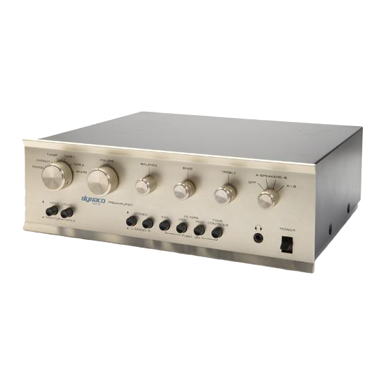
A lead-bending jig can make for quicker, neater assembly. It’s certainly not necessary. Is something in this manual confusing? Does something look wrong? Send your questions by email to dan@akitika.com or dan@updatemydynaco.com. You’ll help yourself and everyone who builds the kit. Figure 1-Assembled PAT-5 Power Supply Page 6 of 21... -
Page 7: Section 3: Building The Power Supply
Section 3: Building the Power Supply This section details the process of building the power supply circuit board. Begin by carefully emptying the contents of the parts envelope into a broad soup bowl, as shown below. In general, you’ll start with the components that lay closest to the board, working your way towards the taller components. -
Page 8: Component Order
Component Order You’ll notice that the component designations in the directions don’t go exactly in order. We have grouped them so that all components with the same value appear together. This makes assembly easier. You’ll find in the parts kit that similar parts, e.g. 8 1N4004 diodes, are typically (though not always) taped together. -
Page 9: Install The Non-Polar Capacitors
Install the non-polar Capacitors These capacitors are not polarized, so it doesn’t matter which way they are installed on the printed circuits. Designation Value Description Done 0.1 µF 100 Volt, film 0.1 µF 100 Volt, film 0.1 µF 100 Volt, film 0.1 µF 100 Volt, film 0.01 µF... -
Page 10: Figure 5-Regulator And Heat Sink Mounting Screws And Soldering Mounting Posts
2. Fasten the regulator to the heat-sink using a 4-40x5/16” Phillips head screw and 4-40 keps nut (a nut with a built-in lock washer) as shown in Figure 5. 3. Insert the regulator/heat-sink assembly into the PCB. 4. Turn the board over and solder the cylindrical projections of the heatsinks to the circular pads on the bottom of the PCB. -
Page 11: Check Your Work
If everything looks good, you’re ready to install the power supply into your PAT-5. Removing the Old Power Supply The mechanical design of the PAT-5 Preamp makes removing the old power supply a lot of work. Your soup bowl will come in handy again as a safe place to collect all the bits and pieces you’ll need to remove to change the power supply. -
Page 12: Figure 8-Remove These 2 Screws And 2 Screws On The Opposite Side
Remove the two 4-40 screws and nuts from the back panel that hold the zig- zag shield and the power supply mounting bracket. Try to not let the nuts or lock washers get away from you (Figure 9). Use a 1/16” Allen wrench to remove all the front panel knobs. I like to turn all the knobs fully counterclockwise before I start. -
Page 13: Connect The Transformer
Connect the Transformer Make absolutely sure that your PAT-5 is unplugged! You will re-use the original Dynaco power transformer. In its new connection arrangement, the total power drawn by the PAT5 drops from 10 Watts to 7 Watts. That’s because the new arrangement is more efficient than the stock arrangement. -
Page 14: Connecting The Ac Line-Side Transformer Wires
Violet-White and Violet transformer wires were twisted together As you perform the steps below, you will untwist these pairs, and form new twisted pairs out of these four wires. Make absolutely sure that your PAT-5 is unplugged! 1. Identify the following 2 transformer wires: a. Violet b. -
Page 15: Connecting Ac Power To The Pcb
Connecting AC Power to the PCB Make absolutely sure that your PAT-5 is unplugged! The only thing that remains to do is to connect the fused 120 volt power to the transformer. Locate the supplied piece of twisted white/black 22 AWG stranded wire. -
Page 16: Testing The New Power Supply
Testing the New Power Supply Safety Warnings: Clean-up and make sure that no tools are inside the preamp. You’re about to power it on to test the output voltages. Remember to be safe, as potentially lethal voltages will be present in the next step. Re-installing the power supply is a lot of work. -
Page 17: Installing The New Power Supply
Installing the New Power Supply Figure 11-Mount new PCB to shield and mounting brackets Installing the new power supply Done? () Pull the Preamp’s AC plug and wait 1 minute before going on. Mount the new power supply to the zig-zag shield using four 4-40 screws and the supplied 4-40 KEPS nuts into the power supply mounting brackets. -
Page 18: Complete Zig-Zag Wall And Back Panel Re-Installation
Complete Zig-Zag Wall and back panel re-Installation Make sure that the PAT-5 Preamp is unplugged before going on! Use two silver colored 4-40 screws and the supplied 4-40 KEPS nuts to fasten the zig-zag shield to the front panel. It’s hard to get your fingers in place to hold the nuts. -
Page 19: Figure 12-Wiring Power From Back To Front With Jumpers
Figure 12-wiring power from back to front with jumpers Figure 13-Separate runs for power to phono stages and line stages Page 19 of 21... -
Page 20: Testing The Power Supply Line-Stage Combination
Measure DC voltage from any of the N15 terminals to any of the GND terminals. It should be -15 Volts, plus or minus 1 volt. Final Re-Assembly Once you have verified correct voltages, it’s time to return your PAT-5 Preamp to service. Putting on the Cover Done? () -
Page 21: Schematic
Schematic Figure 14-Schematic of Power Supply Page 21 of 21...
Need help?
Do you have a question about the PAT-5 and is the answer not in the manual?
Questions and answers