Table of Contents
Advertisement
Quick Links
BLACKMER HD COMPRESSORS
Installation, Operation, and Maintenance Instructions
DISCONTINUED
TABLE OF CONTENTS
SAFETY DATA ..........................................................1
Compressor Data .................................................2
Nameplate Data ...................................................3
Location and Piping..............................................5
Mounting the Compressor Unit ............................5
Compressor Flywheel ..........................................6
V-Belt Drive...........................................................6
Suction Valve Unloaders......................................7
Maximizing Compressor Life................................7
Seal Arrangements...............................................8
Typical Compressor, Drawing..............................9
Relief Valves.........................................................9
4-Way Valves .......................................................9
Liquid Traps ..........................................................9
Temperature and Pressure Switches ..................9
Pressure Gauges .................................................9
SAFETY DATA
This is a SAFETY ALERT SYMBOL.
When you see this symbol on the product, or in the
manual, look for one of the following signal words and
be alert to the potential for personal injury or property
damage.
Warns of hazards that WILL cause serious personal
injury, death or major property damage.
Warns of hazards that CAN cause serious personal
injury, death or major property damage.
Warns of hazards that CAN cause personal injury, or
property damage.
NOTICE
Indicates special instructions which are very important
and must be followed.
MODELS HD942A and HDL942A
Pre-Start up Check List ........................................ 10
Start Up Procedure ............................................... 10
Service Schedule.................................................. 11
Tool List................................................................. 12
Bolt Torque Table ................................................. 12
Crankcase Lubrication.......................................... 13
Setting the Oil Pressure........................................ 13
COMPRESSOR DISASSEMBLY.............................. 14
COMPRESSOR ASSEMBLY.................................... 16
UNLOADER SEAL REPLACEMENT....................... 18
VALVE REPLACEMENT........................................... 18
SEAL (PACKING) REPLACEMENT ........................ 20
BEARING REPLACEMENT...................................... 23
OIL PUMP REPLACEMENT ..................................... 24
EXTENDED STORAGE............................................. 24
TROUBLESHOOTING............................................... 25
NOTICE
Blackmer compressors MUST only be installed in
systems which have been designed by qualified
engineering personnel. The system MUST conform to
all applicable local and national regulations and safety
standards.
These instructions are intended to assist in the
installation and operation of Blackmer compressors
and MUST be kept with the compressor.
Blackmer compressor service and maintenance shall
be performed by qualified technicians ONLY. Service
and maintenance shall conform to all applicable local
and national regulations and safety standards.
Thoroughly review this manual, all instructions and
hazard warnings, BEFORE performing any work on
the compressor.
Maintain ALL system and compressor operation and
hazard warning decals.
For handling liquefied gas, NFPA Pamphlet 58 should
be consulted.
960478
INSTRUCTIONS CB9A-030
Section
901
Effective
Jan 2007
Replaces
Oct 2006
r2010feb
Advertisement
Table of Contents

Subscribe to Our Youtube Channel
Related Manuals for BLACKMER HD942A


Summary of Contents for BLACKMER HD942A
-
Page 1: Table Of Contents
EXTENDED STORAGE..........24 TROUBLESHOOTING..........25 SAFETY DATA NOTICE Blackmer compressors MUST only be installed in This is a SAFETY ALERT SYMBOL. systems which have been designed by qualified When you see this symbol on the product, or in the engineering personnel. The system MUST conform to... -
Page 2: General Information
GENERAL INFORMATION COMPRESSOR DATA TABLE 1 - COMPRESSOR DATA Air-Cooled HD942A Water-Cooled HDL942A MAWP - psia (Bar) 350 (24.1) Displacement CFM (m /hr) @ 350 rpm (Minimum Speed) 52.5 (89.1) -
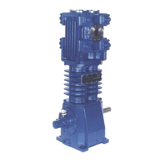
Page 3: Nameplate Data
GENERAL INFORMATION Figure 1 – Air-Cooled HD942A Compressor (Type 'B' Packing shown) MODEL: HD ID#: SERIAL NO: Before proceeding: 1. Note the nameplate data in the space provided above. 2. Obtain the appropriate parts lists for the model in question. - Page 4 GENERAL INFORMATION An 11 character "I.D. No." identifies the construction of the compressor. TABLE 2 - COMPRESSOR ID NUMBER KEY VALVES Code Fields Ductile Iron / PEEK DI/PEEK w/ Unloaders TNT-12 DI/PEEK TNT-12 DI/PEEK w/ Unloaders Stainless Steel SS w/ Unloaders O-RINGS Field 3 Buna-N...
-
Page 5: Installation
INSTALLATION NOTICE: Blackmer compressors must only be installed in systems designed by qualified engineering personnel. System design must conform with all applicable Discharge piping surface temperatures regulations and codes and provide warning of all may be hot during operation (over system hazards. -
Page 6: Compressor Flywheel
V-BELT DRIVES Most Blackmer compressors are driven via V-belts which must be properly aligned and tensioned. Flywheel guard contact with moving parts may be a source of ignition in 1. Lay a straight edge along the face of the motor explosive atmospheres causing severe sheave and compressor flywheel. -
Page 7: Suction Valve Unloaders
Blackmer unloaders are basically a piston and a plunger each application, installation, and operating procedures. atop the suction valve. When pressure is applied to the... -
Page 8: Seal Arrangements
INSTALLATION Seal Type D SEAL ARRANGEMENTS This seal arrangement is designed to allow the These compressors are furnished with three types packing to be vented if desired. Vent openings to of piston rod seals. The type used is noted by the 6 each rod's packing are located in the cylinder casting digit of the compressor's ID Number on the nameplate. -
Page 9: Typical Compressor, Drawing
Blackmer offers various relief valves for gas and Optional temperature switches should be installed with application compatibility. a thermowell as close to the compressor discharge as possible. -
Page 10: Operation
Operating limits listed in the "Compressor Data" inlet and discharge of the compressor. section must not be exceeded. 5. Blackmer compressors are shipped from the factory 3. Check for leakage from the piping and equipment, without oil in the crankcase. Fill with a high quality and repair as necessary. -
Page 11: Maintenance
NOTICE: Blackmer compressor service and maintenance shall be performed by qualified technicians only. Service and maintenance shall conform to all applicable local and national regulations and safety standards. Table 5 – SERVICE SCHEDULE Daily... -
Page 12: Tool List
MAINTENANCE TOOL LIST Description Used For: Blackmer Wrench 790535 Valve Hold-down screw Blackmer Packing Installation Tool 790540 Rod-packing protection during installation. Lower Packing Box Hold-down Ring 3" Adjustable Spanner with 1/4" pins (Blackmer PN 790316) 15/16" socket with 4" extension Piston Nut 3/4"... -
Page 13: Crankcase Lubrication
The oil pump on these models will operate in either direction of crankshaft rotation. Models Quarts Liters HD942A / HDL942A 6.62 SETTING THE OIL PRESSURE (see Figure 6) 1. The oil pressure should be about 25 psig Table 8 - Oil Capacity (1.73 Bar). -
Page 14: Compressor Disassembly
3" adjustable spanner with ¼" pins 4. PISTON REMOVAL (Blackmer PN 790316). a. Rotate the crankshaft by hand to bring a piston e. Place a wooden block (or the end of a mallet to the top dead center position. - Page 15 COMPRESSOR DISASSEMBLY Figure 8 - Packing Boxes, Crosshead and Connecting Rod Detail 8. REMOVING CONNECTING 9. Remove opposite connecting ASSEMBLIES (with the crossheads attached). crosshead assembly. The piston rod is permanently attached to the 10. Rest the crosshead assembly on a bench. crosshead to form a single assembly.
-
Page 16: Compressor Assembly
O-rings with light oil. The packing bore in the crosshead assembly, and the wrist installation tool (Blackmer Part No. 795040) pin bushing in the connecting rod with grease. must be used to avoid damaging the packing b. - Page 17 COMPRESSOR ASSEMBLY e. Place the upper shim washer(s) over the rod 7. CYLINDER ASSEMBLY onto the piston. a. The cylinder should be installed with the valves Install the piston cap (without the O-ring). removed. g. Tighten the piston nut on securely. b.
-
Page 18: Unloader Seal Replacement
UNLOADER SEAL REPLACEMENT 1. Remove the unloader cap and O-ring. 4. Inspect and replace the seals as needed - note the 2. Remove the unloader body from the cylinder head seal orientation! (a strap wrench is helpful). 5. Inspect the unloader body bore - it must be clean 3. - Page 19 1. Remove the valve cap and O-ring from each valve. 2. Remove the valve hold down screw with a spanner wrench (Blackmer PN 790535). 3. VALVE REMOVAL a. Remove the valve cover plate capscrews then lift off the cover plate and O-ring.
-
Page 20: Seal (Packing) Replacement
SEAL (PACKING) REPLACEMENT Clean and inspect all parts, replacing as Two seals separated by a distance piece seal the gas in needed. the cylinder and prevent contamination by the crankcase oil. The upper seal consists of pairs of e. Refer to the appropriate drawing for the proper segmented packing rings, while the lower seal utilizes a orientation of the packing cups and rings. - Page 21 SEAL (PACKING) REPLACEMENT Figure 17 - Type 'B' Packing Detail Figure 19 - Type 'D' Packing Detail CB9A-030 page 21/28...
- Page 22 SEAL (PACKING) REPLACEMENT Figure 20 - Lower Packing Assembly 3. LOWER PACKING BOX a. Remove both retainer rings, then remove the old packing, spring, and washers. b. Clean the packing box in a suitable solvent. Do not insert objects or fingers in Inspect the bore for wear, roughness, or inspection cavity.
-
Page 23: Bearing Replacement
BEARING REPLACEMENT NOTICE: When replacing the bearings, the entire c. Note the proper orientation and carefully press bearing assembly, including the bearing cup and the outboard bearing cup into the bearing the bearing cone, must be replaced. carrier assembly. d. Press a bearing cone onto each end of the 1. -
Page 24: Oil Pump Replacement
OIL PUMP REPLACEMENT 4. Place the spring and the drive cone in the end of the crankshaft. 5. Note the slot in the end of the crankshaft and the drive tab on the back of the oil pump assembly. Install the oil pump assembly into the bearing carrier with the tab and slot aligned. -
Page 25: Troubleshooting
TROUBLESHOOTING IF PROBLEM PROBLEM STEP PROBABLE CAUSE WHAT TO CHECK STILL EXISTS GO TO STEP ... 4-Way Valve Leaking Lubricate with a stick lubricant compatible with (when equipped) material being transferred. Check condition of rings by restricting discharge Worn or Broken Piston Rings line. - Page 26 NOTES CB9A-030 page 26/28...
- Page 27 ATEX zone. Closed inlet or outlet valves can result in excess compressor surface temperature conditions. Intended Use: Blackmer compressors are intended for use in liquefied gas transfer or gas compression applications. The compressor must be operated in systems, with gasses and at conditions for which it is specifically designed and sized.
- Page 28 1528, ." " 3, e .5...
Need help?
Do you have a question about the HD942A and is the answer not in the manual?
Questions and answers