Table of Contents
Advertisement
Advertisement
Table of Contents

Related Manuals for Birch BP-525D


Summary of Contents for Birch BP-525D
- Page 1 BP-525D DIRECT THERMAL BAR CODE PRINTER USER’S MANUAL...
-
Page 2: Table Of Contents
Contents Copyright Declaration........i 1. Introduction ........... ii Product Introduction ................ii 2. Operations Overview ........1 2.1 Unpacking and Inspection ..............1 2.2 Printer Overview ..................2 2.2.1 Front View ..................2 2.2.2 Interior view..................3 2.2.3 Rear View..................4 3. Setup ..........5 3.1 Setting Up the Printer ................5 3.2 Loading the Media ...................5 3.3 Diagnostic Tool ..................8 3.5.1 Start the Diagnostic Tool...............8... -
Page 4: Introduction
1. Introduction Product Introduction Thank you for purchasing bar code printer . Although the printer delivers reliable, superior performance. This printer provides direct thermal printing at user selectable speed of: 2.0, 3.0, 4.0 or 5.0 ips. It accepts roll feed, die-cut, and fan-fold media with gap or black mark. All common bar codes formats are available. - Page 5 Note: The maximum printing ratio per dot line is 15% for this printer. To print the full web black line, the maximum black line height is limited to 40 dots, which is 5mm for 203 DPI resolution printer.
-
Page 6: Operations Overview
2. Operations Overview 2.1 Unpacking and Inspection This printer has been specially packaged to withstand damage during shipping. Please carefully inspect the packaging and printer upon receiving the bar code printer. Please retain the packaging materials in case you need to reship the printer. Unpacking the printer, the following items are included in the carton. -
Page 7: Printer Overview
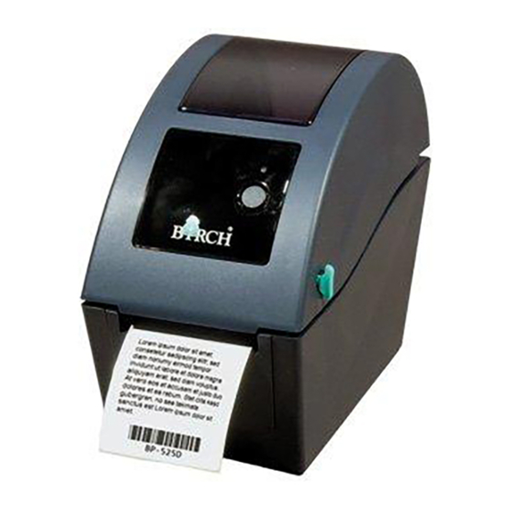
2.2 Printer Overview 2.2.1 Front View 1. Top cover open lever 2. MicroSD card socket 3. Media view window 4. LED indicator 5. Feed button 6. Paper exit chute * Recommended MicroSD card specification. SD card spec SD card capacity Approved SD card manufacturer V1.0, V1.1 MicroSD 128 MB... -
Page 8: Interior View
2.2.2 Interior view 1. Top cover 2. Media holder 3. Media guide 4. Printhead 5. Gap sensor (receiver) 6. Gap sensor (transmitter) 7. Black mark sensor 8. Platen roller... -
Page 9: Rear View
2.2.3 Rear View 1. Power switch 2. Power jack socket 3. USB interface 4. RS-232C interface 5. Fan-fold paper entrance chute 6. Ethernet interface (Option) -
Page 10: Setup
3. Setup 3.1 Setting Up the Printer 1. Place the printer on a flat, secure surface. 2. Make sure the power switch is set to “off”. 3. Connect the printer to the computer with the provided USB cable. 4. Plug the power cord into the AC power cord socket at the rear of the printer, and then plug the power cord into a properly grounded power outlet. - Page 11 4. Place the roll between the holders and close them onto the core. Sensor Platen roller 5. Place the paper, printing side face up, through the media guides, media sensor and place the label leading edge onto the platen roller. Media guides 6.
- Page 12 7. Use “Diagnostic Tool” to set the media sensor type and calibrate the selected sensor. (Start the “Diagnostic tool” Select the “Printer Configuration” tab Click the “Calibrate Sensor” button) Note: Please calibrate the gap/black mark sensor when changing media. Loading path for roll labels...
-
Page 13: Diagnostic Tool
Diagnostic Tool The Diagnostic Utility is a toolbox that allows users to explore the printer's settings and status; change printer settings; download graphics, fonts, and firmware; create printer bitmap fonts; and to send additional commands to the printer. Using this convenient tool, you can explore the printer status and settings and troubleshoot the printer. -
Page 14: Printer Function (Calibrate Sensor, Ethernet Setup, Rtc Setup
3.3.2 Printer Function (Calibrate sensor, Ethernet setup, RTC setup………) 1. Select the PC interface connected with bar code printer. 2. Click the “Function” button to setting. 3. The detail functions in the Printer Function Group are listed as below. Function Description Initialize the printer and restore the settings to Factory Default... -
Page 15: Install Microsd Memory Card
3.4 Install MicroSD Memory Card 1. Open the SD memory card cover. 2. Insert the MicroSD card into the socket. 3. Close the memory card cover. * Recommended SD card specification. SD card spec SD card capacity Approved SD card manufacturer V1.0, V1.1 MicroSD 128 MB Transcend, Panasonic... -
Page 16: Led And Button Functions
4. LED and Button Functions This printer has one button and one three-color LED indicator. By indicating the LED with different color and pressing the button, printer can feed labels, pause the printing job, select and calibrate the media sensor, print printer self-test report, reset printer to defaults (initialization). -
Page 17: Gap/Black Mark Sensor Calibration
Power on utilities The LED color will be changed as following pattern: LED color Amber Amber Green Green/Amber Red/Amber Solid green Functions (5 blinks) (5 blinks) (5 blinks) (5 blinks) (5 blinks) 1. Gap / black mark sensor calibration Release 2. - Page 18 internal configuration (self-test) on label and then enter the dump mode. To calibrate gap or black mark sensor, depends on the sensor setting in the last print job. Please follow the steps below to calibrate the sensor. 1.Turn off the power switch. 2.
- Page 19 Self-test Printer will print the printer configuration after gap/black mark sensor calibration. Self-test printout can be used to check if there is any dot damage on the heater element, printer configurations and available memory space. Print head test pattern Printer model name & Main board firmware version Printed mileage Main board firmware checksum Serial port setting...
-
Page 20: Printer Initialization
Hex decimal data related to ASCII Data left column of ASCII data Note: 1. Dump mode requires 2” wide paper width. 2. Turn off / on the power to resume printer for normal printing. 3. Press FEED button to back to the previous menu. 4.3.3 Printer Initialization Printer initialization is used to clear DRAM and restore printer settings to defaults. -
Page 21: Set Black Mark Sensor As Media Sensor And Calibrate The Black Mark Sensor
Reference Point 0,0 (upper left corner) Offset Tear Mode Peel off Mode Cutter Mode Serial Port Settings 9600 bps, none parity, 8 data bits, 1 stop bit Code Page Country Code Clear Flash Memory IP Address DHCP 4.3.4 Set Black Mark Sensor as Media Sensor and Calibrate the Black Mark Sensor Please follow the steps as below. - Page 22 Please follow the procedures below to skip an AUTO.BAS program. 1. Turn off printer power. 2. Press the FEED button and then turn on power. 3. Release the FEED button when LED becomes solid green. The LED color will be changed as following: Amber red (5 blinks) amber (5 blinks)
-
Page 23: Troubleshooting
5. Troubleshooting The following guide lists the most common problems that may be encountered when operating this bar code printer. If the printer still does not function after all suggested solutions have been invoked, please contact the Customer Service Department of your purchased reseller or distributor for assistance. -
Page 24: Print Problem
5.2 Print Problem Problem Possible Cause Recovery Procedure Check if interface cable is well Re-connect cable to interface. connected to the interface connector. The serial port cable pin configuration is Please replace the cable with pin to pin not pin to pin connected. connected. -
Page 25: Maintenance
6. Maintenance This session presents the clean tools and methods to maintain your printer. 1. Please use one of following material to clean the printer. Cotton swab (Head cleaner pen) Lint-free cloth Vacuum / Blower brush 100% ethanol 2. The cleaning process is described as following: Printer Part Method Interval... - Page 26 Regularly clean the print head and supply sensors once change a new media to keep printer performance and extend printer life. The maximum printing ratio per dot line is 15% for this printer. To print the full web black line, the maximum black line height is limited to 40 dots, which is 5mm for 203 DPI resolution printer.
-
Page 27: Revise History
Revise History Date Content Editor...
Need help?
Do you have a question about the BP-525D and is the answer not in the manual?
Questions and answers