Table of Contents
Advertisement
Document No.:KE-4010-11
Operation Manual
KITZ F Series Pneumatic Valve Actuators
Thank you for having chosen KITZ products.
For safe and trouble-free use of the products, ensure to carefully
read all instructions of this manual before handling of the product.
Keep this manual in a convenient place for easy access of all valve
operating personnel.
for
Advertisement
Table of Contents

Related Manuals for Kitz F Series

Summary of Contents for Kitz F Series
- Page 1 Document No.:KE-4010-11 Operation Manual for KITZ F Series Pneumatic Valve Actuators Thank you for having chosen KITZ products. For safe and trouble-free use of the products, ensure to carefully read all instructions of this manual before handling of the product. Keep this manual in a convenient place for easy access of all valve operating personnel. ...
- Page 2 Document No.:KE-4010-11 NOTES TO USERS This manual applies to the KITZ F Series Pneumatic Valve Actuators. For actuators of automatically operated value, refer to the operation manual of relevant actuators prepared by the manufacturers. SAFETY CAUTIONS This manual calls users’ careful attention to the dangers and hazards that may be caused to personnel or properties during handling, storage, installation, operation or maintenance of the product. Such dangers and hazards are specifically highlighted in the operation manual with either one of the following marks. A warning indicates a potentially hazardous condition that may result in serious injury or death of personnel, if such a warning is ignored. A caution indicates a potentially hazardous condition that may result in minor injury to personnel or damage to properties, if such a caution is ignored. Indicate to call attention of an action. Indicates prohibition of an action. Indicates mandatory implementation of an action. This manual provides users with the instructions on correct use of KITZ F Series pneumatic valve actuators. Ensure to carefully read all the items of this manual before handling, storage, installation, operation and maintenance of the product. This manual covers the normal use of the product as a general guide to users, but does not necessarily cover every condition or situation that may be caused to users while using the product. If technical assistance beyond the scope of this manual is required, users are recommended to contact KITZ Corporation or the distributors in their locations. Numerical limits given in this manual such as operating pressures and service temperatures are specified in consideration of safe and trouble-free operation of the products. It is forbidden to use the product in ...
-
Page 3: Table Of Contents
5. Dimensions and Mass ・・・・・・・・・・・・・・・・・・・・・・・・・・・・・・・・・・・・・・・・・・・・・・3 6. Design Specifications ・・・・・・・・・・・・・・・・・・・・・・・・・・・・・・・・・・・・・・・・・・・・・・・・・・4 7. Product Identification Plate ・・・・・・・・・・・・・・・・・・・・・・・・・・・・・・・・・・・・・・・・・・・・4 8. Actuator Driving Mechanism ・・・・・・・・・・・・・・・・・・・・・・・・・・・・・・・・・・・・・・・・・・・・5 9. Output Torques ・・・・・・・・・・・・・・・・・・・・・・・・・・・・・・・・・・・・・・・・・・・・・・・・・・・・・・6 10. Supply of Air Operation Pressure ・・・・・・・・・・・・・・・・・・・・・・・・・・・・・・・・・・・・・・・・7 11. Air Consumption ・・・・・・・・・・・・・・・・・・・・・・・・・・・・・・・・・・・・・・・・・・・・・・・・・・・・・・8 12. Handling and Storage of Actuators and Actuated Valves ・・・・・・・・・・・・・・・・・・・・・・9 13. Valve Opening Positions Set for Shipment ・・・・・・・・・・・・・・・・・・・・・・・・・・・・・・・・・10 14. Mounting Actuators on Valves ・・・・・・・・・・・・・・・・・・・・・・・・・・・・・・・・・・・・・・・・・・・10 15. Adjusting Valve Opening Range ・・・・・・・・・・・・・・・・・・・・・・・・・・・・・・・・・・・・・・・・・・13 16. Mounting KITZ Optional Accessories on Actuators ・・・・・・・・・・・・・・・・・・・・・・・・・・15 17. Optional Design Specifications ・・・・・・・・・・・・・・・・・・・・・・・・・・・・・・・・・・・・・・・・・・・17 18. Automatic Operation of Actuators ・・・・・・・・・・・・・・・・・・・・・・・・・・・・・・・・・・・・・・・・17 19. Manual Operation of Actuators ・・・・・・・・・・・・・・・・・・・・・・・・・・・・・・・・・・・・・・・・・・・18 20. Inspection and Maintenance of Actuators and Actuated Valves ・・・・・・・・・・・・・・・・19 21. Disassembly and Reassembly of Actuators ・・・・・・・・・・・・・・・・・・・・・・・・・・・・・・・・・20 22. KITZ Standard Spare Parts for KITZ Type FA/FAS Actuators・・・・・・・・・・・・・・・・・・・31 23. Trouble Shooting ・・・・・・・・・・・・・・・・・・・・・・・・・・・・・・・・・・・・・・・・・・・・・・・・・・・・・・34 24. Notes to Users ・・・・・・・・・・・・・・・・・・・・・・・・・・・・・・・・・・・・・・・・・・・・・・・・・・・・・・・・35 25. Product Warranty ・・・・・・・・・・・・・・・・・・・・・・・・・・・・・・・・・・・・・・・・・・・・・・・・・・・・・・35 26. Emergency Call for Technical Assistance ・・・・・・・・・・・・・・・・・・・・・・・・・・・・・・・・・・・35 ... -
Page 4: Attentions For User's System Design ・・・・・・・・・・・・・・・・・・・・・・・・・・・・・・・・・・・・1
1. Corrosive environment 2. Explosiveness, flammable environment (explosion-proof specification) 3. Receive direct sunlight 4. Vibration environment (When an actuator increases vibration more than 0.5G) Do not install the product under water. (Include high humidity environment and be buried in snow) Do not pressurize spring return type actuator s breathing port. Prevent entering dust, rainwater or waste into actuators through the breathing port. 2. Product Features 2.1 KITZ F Series pneumatic valve actuators are provided with output torque characteristics suitable for operation of both KITZ ball valves and KITZ butterfly valves. 2.2 KITZ F Series pneumatic valve actuators are designed for direct modular mounting of KITZ optional accessories on the actuator housing. 3. Product Codes KITZ F Series pneumatic valve actuators are available in two types, depending on the drive mechanism. Type FA is for the double action drive. Type FAS is for the spring return drive. For operation of valves of various sizes, both types are available with the Size 1 through Size 6, which are identified by the last digit of each product code, such as FA-1 or FAS-2. ... -
Page 5: Mounting Of Actuators On Valves ・・・・・・・・・・・・・・・・・・・・・・・・・・・・・・・・・・・・・・2
Document No.:KE-4010-11 Page: 2/58 4. Mounting of Actuators on Valves KITZ F Series pneumatic valve actuators are mounted on KITZ ball valves with a factory supplied bracket connector, or directly mounted on ISO mounting pads of KITZ butterfly valves. ... - Page 6 Document No.:KE-4010-11 Page: 3/58 5. Dimensions and Mass Type FA double action actuators 4‐M5 Depth 10 4-R3 Depth L3 4-R2 Depth L2 4-R2 Depth L2 4-R1 Depth L1 4-R1 Depth L1 4-R1 Depth L1 FA-6 ONLY A view W1 W2 W3 W4 E1 H2 H4 H5 H6 H7 b1 d1 R1×L1 R2×L2 R3×L3 R4×L4 FA/FAS-1 50 M6×9 M5×7.5 FA-1 54 30 55 12 76 12 15 Rc1/4 FA/FAS-2 70 M6×9...
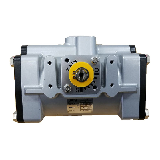
- Page 7 1.29 2.29 5.27 Standard operation pressure 0.4 MPa Operation pressure range *1 0.3〜0.7 MPa Housing shell test pressure 0.97 MPa Valve opening position 90°with 7 division marks including [O] and[S] indicator Service temperature range −20℃〜+80℃ *2 Bottom pad for mounting on ISO5211 valves *1. Contact KITZ Corporation for technical advice, if the operating pressure is lower than 0.4MPa. *2. The air supply must not be frozen. 7. Product Identification Plate For the identification of the product code and service conditions, a metal plate is attached to the actuator housing. ID plate for FA-1 actuator ID plate location ...
-
Page 8: Actuator Driving Mechanism ・・・・・・・・・・・・・・・・・・・・・・・・・・・・・・・・・・・・・・・・・・・・5
Document No.:KE-4010-11 Page: 5/58 8. Actuator Driving Mechanism 8.1 Type FA double action actuators The air pressure supplied into Chamber[A] through Port ① pushes the pistons and the gear rack outwards, and releases the air left in Chamber[B] through Port ②. The gear rack rotates the piston gear and the shaft counter-clockwise to drive the valve. Reverse supply of the air pressure reversely activates valve operation. 8.2 Type FAS spring return actuators The air pressure supplied into Chamber [A] through Port ① pushes the pistons and the gear rack outwards, compressing the spring, and releases the air left in Chamber[B] through Port ②. The gear rack rotates the piston gear and the shaft counter-clockwise to drive the valve. At the moment the air in Chamber [A] is discharged through the solenoid valve, the spring force pushes the pistons to the reverse direction, and the gear rack rotates the pinion gear and the shaft clockwise to reversely drive the valve. ... - Page 9 Document No.:KE-4010-11 Page: 6/58 9. Output Torques 9.1 Output torques of Type FA double action actuators UNIT: N・m Operation pressure (air) ...
-
Page 10: Supply Of Air Operation Pressure ・・・・・・・・・・・・・・・・・・・・・・・・・・・・・・・・・・・・・・・・7
10. Supply of Air Operation Pressure 10.1 For the actuator factory-assembled with a solenoid valve, provide the air tubing between the air compressor and the solenoid valve. Air inlets are Rc 1/4. 10.2 Use copper, coated copper or plastic tubes of an adequate diameter and wall thickness. Clean tube bores to remove all foreign residues and tightly seal all connections to avoid leakage of air during a travel from the compressor. 10.3 If you want to mount your own solenoid valves other than those factory-assembled, select the following type. For Type FA actuators, 4-way solenoid valves are used. For Type FAS actuators, 3-way or 4-way solenoid valves with plug up just one port are used. 10.4 Air inlets are Rc1/4. Use 6mm or smaller tubes, and hexagonal fittings of 19mm and smaller width of flat . Contact KITZ Corporation for technical advice, if you want to use larger tubes for faster operation of actuators. 10.5 Keep the air always free from dust and moisture ( -15℃ or lower dew point under the atmospheric pressure ), using air-filters and air-dryers. 10.6 Choose the capacities of your own accessories and the sizes of auxiliary air tubing, in consideration of possible loss of air pressure during a travel from the compressor. 10.7 The exact volume (Q) of air supply required per minute for actuators must be known before the air tubing installation so that the provided operation pressure may be sufficient to properly drive actuators and valves. Calculate your air supply requirement with the following equation. 10.8 The required air pressure must be kept constant at the air inlet of an actuator. Insufficient air supply causes intermittent piston drive and results in malfunction of actuators. Q = V(P + 0.1013) / 0.1013 x 60/t [ /min.(ANR)] ... - Page 11 Document No.:KE-4010-11 Page: 8/58 11. Air Consumption Air consumption means the volume (Q) of the air released to the atmosphere from an actuator operating [n] times forward and backward per hour as converted to the average volume per minute. Decide the capacity of an air compressor using the result of the following calculation. We recommend to use an air reservoir of an adequate size to constantly operate an actuator at the preset time. ◆ Air consumption of Type FA double action actuators: Q = (V1 + V2)(P + 0.1013) / 0.1013 x n/60 [ /min.(ANR)] ◆ Air consumption of Type FAS spring return actuators: Q = V3 (P + 0.1013) / 0.1013 x n/60 [ /min.(ANR)] V1, V2 and V3: Volume of actuator housing [ ] ...
-
Page 12: Handling And Storage Of Actuators And Actuated Valves ・・・・・・・・・・・・・・・・・・・・・・9
Appropriately design the total length of air tubing. Too long air tubing causes pressure loss or insufficient flow rate of the air, and results in malfunction or failure of an actuator. 12. Handling and Storage of Actuators and Actuated Valves 12.1 Store actuators and valves in cool, dry, corrosion-free environment to keep them rust-free and prevent their malfunction, although surfaces are appropriately finished for primary protection. 12.2 Actuators and actuated valves are provided with dust protectors and packed individually for damage prevention. Don’t unpack them and don’t remove protectors until you are ready to install them on pipes. 12.3 Overloading actuators and valves must be prevented. Don’t fall them on the ground. Don’t place any other objects on them. Don’t step on them. Actuators or actuated valves are individually packed and all openings and connections are sealed for dust prevention. Don’t unpack them and don’t remove protectors until you are ready to install them on pipes. Modification of actuators or actuated valves is forbidden, unless accepted by KITZ Corporation or the authorized modification shops in advance. Carefully handle actuators packed particularly in cardboard cases, since the cases might have become very fragile due to moisture and other causes. Care must be taken to handle actuators equipped with solenoid valves and other accessories during storage or transportation. Store actuators or actuated valves in cool, dry, corrosion-free environment to keep them rust-free and prevent their malfunction or failure. ... -
Page 13: Valve Opening Positions Set For Shipment ・・・・・・・・・・・・・・・・・・・・・・・・・・・・・・・・・10
(1) If solenoid valves are set for AIR-TO-OPEN mode ( or positioners are set for reverse action ), valves are fully closed. (2) If solenoid valves are set for AIR-TO-CLOSE mode ( or positioners are set for direct action ), valves are fully open. 13.3 KITZ butterfly valves equipped with Type FA double action actuators are all shipped with the disc set fully closed. 13.4 KITZ ball and butterfly valves equipped with Type FAS spring return actuators are all shipped in the de-energized condition. 14. Mounting Actuators on Valves 14.1 Mount F Series actuators on KITZ butterfly valves, referring to the illustration provided below. Type FAS spring return actuator Type FA double action actuator Actuator mounting pad Spring washer <145B> ... - Page 14 Document No.:KE-4010-11 Page: 11/58 14.2 Mount F Series actuators on KITZ ball valves, referring to the illustration provided below. Type FA double action actuator Spacer <155> Bracket connector <92> Spring washer <145> Hexagon screw <94> Actuator mounting bracket <93> Top gland nut <34A> Gland B Unnecessary Gland A <7A> Gland bolt <36> parts <7B> Snap ring <48>...
- Page 15 Document No.:KE-4010-11 Page: 12/58 When Type FAS spring return actuator is used outside or wet condition, water may enter into a spring unit in some actuator orientation. Rotate a part avoiding entering water ( Mizukiller ) clockwise and set it adequate position that open side tip of Mizukiller shall be upward. Open side tip Normal position of Mizukiller Mizukiller (1) Actuator supply port faces upward. Open side tip shall be upward. (2) Actuator supply port faces ground. Open side tip shall be upward. (3) Actuator supply port feces side and spring case is upward. Open side tip shall be upward. (4) Actuator supply port faces side and spring case is downward. ...
-
Page 16: Adjusting Valve Opening Range ・・・・・・・・・・・・・・・・・・・・・・・・・・・・・・・・・・・・・・・・・・13
Document No.:KE-4010-11 Page: 13/58 15. Adjusting Valve Opening Range adjustment Stopper bolt for adjustment Stopper bolt for to opening direction to closing direction 15.1 Release the compressed air from the actuator housing. Loosen a hexagon nut and adjust the position of either one of two stopper bolts illustrated above for your desired valve opening position. The dimensional requirements of butterfly valve discs (A less B in Table 3) or ball valve balls ([L] in Table 4) must be satisfied. Refer to Table 5 on the sizes of stopper bolts. 15.2 Clockwise rotation of the stopper bolt makes the valve operation range smaller, and counter-clockwise rotation makes it larger. 15.3 After having tightened the nuts, supply the compressed air to the port and check the valve opening range. Repeat this work until you have a satisfactory result. ... - Page 17 Document No.:KE-4010-11 Page: 14/58 Table 3: Adjustment for KITZ butterfly valves (*1) Valve size A less B [mm] (*1) Set [A less B] to zero for KITZ 10XJ 10DJ 16DJ 20DJ UB Series butterfly valves. 11/2 2 to 3 0 to 2 2 to 3 to 3 (*2) Contact KITZ Corporation for 3 to 4 21/2 2 to 3 3 to 4 information on 16/20DJ250 to 6 9 to 11 8 to 9 5 to 6...
-
Page 18: Mounting Kitz Optional Accessories On Actuators ・・・・・・・・・・・・・・・・・・・・・・・・・・15
Document No.:KE-4010-11 Page: 15/58 16. Mounting KITZ Optional Accessories on Actuators KITZ F Series pneumatic valve actuators employ NAMUR dimensions for an accessory mounting pad on the top. Any NAMUR dimensioned solenoid valve can be directly mounted on the actuator without tubing. For detailed information on mounting KITZ optional accessories on F Series actuators, refer to the operating instructions provided for each optional accessory. ◆ Mounting diagram of KITZ optional accessories ◆ Mounting view of KITZ optional accessories ... - Page 19 Document No.:KE-4010-11 Page: 16/58 ◆ Design specifications of KITZ optional accessories Accessories Specification NAMUR solenoid valves Power supply Explosion proof :AC100V/110V 50/60Hz Weather proof indoor use :AC200V/220V 50/60Hz Weather proof outdoor use :DC24V Air inlets:Rc1/4 Maximum working pressure:0.7MPa Switch boxes Switch boxes with built-in sensitive switches With built-in sensitive switches Resistive load :11A AC125V/250V :0.5A DC125V :0.25A DC250V Inductive load :7A AC125/250V With built-in proximity switches Switch boxes with built-in proximity switches ...
-
Page 20: Optional Design Specifications ・・・・・・・・・・・・・・・・・・・・・・・・・・・・・・・・・・・・・・・・・・・17
Document No.:KE-4010-11 Page: 17/58 17. Optional Design Specifications The following design specifications can be optionally accommodated for KITZ F Series pneumatic valve actuators. For details, refer to Appendix of this manual. Optional Design Specifications Options Design specifications Low temperature -40℃(-40°F) to +60℃(+140°F) ambient Service temperatures High temperature -20℃(-4°F) to +100℃(+212°F) ambient for 0.5MPa operating pressure 5K Spring cartridges for 0.3MPa operating pressure 3K to open valves with spring repulsing force AIR-FAIL-OPEN mode Adjustment of valve opening range to stop valve travel at a desired position ... -
Page 21: Manual Operation Of Actuators ・・・・・・・・・・・・・・・・・・・・・・・・・・・・・・・・・・・・・・・・・・・18
Document No.:KE-4010-11 Page: 18/58 (5) Check if the operating pressure has been set with your required specification. (6) Check if an equipped air regulator has been set for your required operation pressure. (7) If a speed controller is equipped, adjust the flow rate of the exhaust air to match your required operation speed. Use either compressed instrumentation air or nitrogen gas for operation of actuators. Use of any other operating medium may affect the function of actuators. Use of operation pressure exceeding 0.7MPa may damage actuators or accessories. Keep the operation medium completely dry. High humidity causes rust and may result in malfunction or failure of actuators or accessories. A part to avoid entering water into a spring case ( Mizukiller ) is installed on spring return type actuator s breathing port. And The Mizukiller is sealed with a sticker. Remove the sticker before running automated operation. (For products shipped before December 2009, a cap is installed on spring return type actuator s breathing port instead of the Mizukiller. Remove the cap before running automated operation. If the cap remains, actuator speed may become slow.) When Type FAS spring return actuator is used outside or in wet condition, the Mizukiller has to be installed into it. If the Mizukiller is not installed, water may enter into ... -
Page 22: Inspection And Maintenance Of Actuators And Actuated Valves ・・・・・・・・・・・・・・・・19
Don’t forget to remove the spanner or the wrench used for manual operation after the actuator is reset for automated operation. Otherwise the spanner or the wrench may jump out and injure nearby personnel and damage nearby properties. Ensure to equalize the housing pressure with the atmospheric level before manual operation. Leaving the residual air pressure in the housing is too hazardous to nearby personnel and properties. 19.3 Manual operation of energized Type FA double action actuators (1) All KITZ optional solenoid valves are provided with a manual switch. Choose any one of the following solenoid valves for manual operation of the actuators being energized. ① KOGANEI Model A180 Keep pressing a switch with the tip of a screwdriver for manual operation. Removal of the screwdriver returns the actuator to the original automated operation mode. ② CKD Model 4F310 Rotate a knob for manual operation. ③ KANEKO Model MK15G Pull out a switch for manual operation. ④ ASCO SCXD551 ... -
Page 23: Disassembly And Reassembly Of Actuators ・・・・・・・・・・・・・・・・・・・・・・・・・・・・・・・・・20
◇ Ensure that the valve opening or closing range is correctly maintained in accurate response to a signal currency or a signal pressure of actuators and accessories. ◇ Check the air leakage through all air tubing connections and valves. ◇ Check an abnormal noise generated from the air tubing or valves. ◇ Check vibration of actuators and valves. ◇ Ensure that all bolts and nuts are securely tightened. Don’t use any spindle oil or gear oil for lubrication of actuators and accessories. An abnormal noise may be generated due to valve seat galling ( valve seats getting stuck with foreign objects ) or blockage of actuator air tubing caused by internal residues. Take corrective measures immediately, since damage of valve seats and malfunction of actuators and valves may be caused by negligence of such problems. Ensure to replace terminals of electric devices, if needed, with those designed with the same specifications. Different design specifications could be a cause of technical troubles. Leaving an abnormal vibration of actuators and valves also causes equipment failure. Support the piping system securely. 21. Disassembly and Reassembly of Actuators 21.1 KITZ F Series pneumatic valve actuators are available in two types, depending on the basic drive mechanism. While Type FA actuators are designed for double action drive, spring cartridge modules are added to Type FA mechanism to make Type FAS spring return actuators. When you disassemble or reassemble these actuators for inspection or maintenance, the utmost care must be taken to respect the warnings and cautions mentioned here. ... - Page 24 In such a case, disassembly work must be immediately discontinued to prevent the spring cartridge from jumping out. If you have a concern of damage of a spring cartridge, securely retighten spring cover bolts, and replace the actuator itself without removal of the spring cartridge. Before disassembling, loosen the hexagon headed bolt under air port to depressurize the housing. Hexagon headed bolt Disassembling F type actuator is prohibited. Please ask KITZ or authorized maintenance shops to disassemble them for maintenances or disposal. Spring retainer Retainer guide Spring ...
- Page 25 Document No.:KE-4010-11 Page: 22/58 On disassembly of KITZ F Series pneumatic valve actuators: Place work benches in a spacious, clean room. Equalize the housing pressure with the atmospheric level, before disassembly. After the air tubing has been disassembled, appropriately protect air inlet/outlet ports of an actuator to keep them dust-free until subsequent reassembly. The internal surface of the housing and sliding parts such as shafts, pistons and bearings must be carefully handled and stored to avoid scratches or damages, until subsequent reassembly. On reassembly of KITZ F Series pneumatic valve actuators: Place work benches in a spacious, clean room. Clean all parts and components, and ensure that they are free from dust and rust. Lubricate pistons, bearings, shafts and the internal surface of the housing with Kyodo Oil MULTEMP AC-J or the equivalent. Contact KITZ Corporation for advice, if this lubricant is not available to you. Use KITZ genuine parts to replace O-rings, gaskets and other consumables, referring to Section 22 of this manual. Carefully mount all sealing parts not to cause scratches or damages to the sealed surface of an actuator housing and adjacent parts. Assemble a gear rack with the housing, paying a careful attention to the mounting direction and position. Assemble pistons and shafts with the utmost care not to cause scratches or damages to adjacent sliding surfaces. ...
- Page 26 Document No.:KE-4010-11 Page: 23/58 21.2 Disassembly of KITZ F Series pneumatic valve actuators (1) Make the air pressure the same as the atmospheric level. (2) Gradually loosen all air tubing fittings and ensure that the housing pressure has been equalized with the atmospheric level. Dismantle an actuated valve from the pipeline and disassemble an actuator from the valve. (3) Unthread a hexagon headed bolt and a seal washer near the solenoid valve mounting pad. It is possible that piston O-rings are worn and cause air leakage and pressurize the interior of the housing. Therefore, before working on disassembly of an actuator, gradually loosen the hexagon headed bolt and check that the housing pressure has been equalized with the atmospheric level ( Fig.1 ). Snap ring <48B> Indicator <97> Headed screw <39> Indicator plate <98> Seal washer <155B> Hexagon headed bolt <13B> ( Fig.1) ( Fig.2 ) ...
- Page 27 Document No.:KE-4010-11 Page: 24/58 (7) Rotate the shaft and move another piston toward the end cover opening. Loosen a hexagon headed bolt and remove the second piston from the housing. Also remove a gear rack ( Fig.5 ). Rack <103> Snap ring <48A> Thrust washer <47A> Thrust bearing <47B> Hexagon headed bolt <13A> Fig.5 ...
- Page 28 Document No.:KE-4010-11 Page: 25/58 21.3 Reassembly of KITZ F Series pneumatic valve actuators (1) Lubricate a larger O-ring, a smaller O-ring, a bearing, and a back-up ring with Kyodo Oil MULTEMP AC-J lubricant or the equivalent, and assemble them with the piston (Fig.8). Contact KITZ Corporation for advice, if this lubricant is not available. O-ring <45D> Bearing B <67B> Shaft <3> Piston <177> Back-up ring <146> O-ring <45C> O-ring <45A> Piston bearing <67C> Fig.8 Fig.9 ...
- Page 29 Document No.:KE-4010-11 Page: 26/58 (4) Lubricate the shaft assembled with the housing. Mount a thrust washer and a thrust bearing on the shaft securely with a snap ring ( Fig.12 ). Housing <1> Snap ring <48A> Thrust washer <47A> Thrust bearing <47B> Piston / O-ring / bearing / back-up ring Fig.12 Fig.13 ...
- Page 30 Document No.:KE-4010-11 Page: 27/58 (8) Mount a stopper bolt, a seal washer and a hexagon nut on an end cover. Lubricate an O-ring and assemble it with the end cover ( Fig.16 ). Mount the end cover on the housing opening with hexagon headed bolts ( Fig.17 ). For reassembly of Type FAS spring return actuators, the spring cartridge must be mounted on the housing opening, instead of the end cover. Hexagon nut <132A> Hexagon headed bolt <35> O-ring <45F> End cover <2A> Seal washer <155A> Hexagon nut <133> Fig.16 Fig.17 ...
- Page 31 Document No.:KE-4010-11 Page: 28/58 ④ Leak test should be done after 15minuits to 30minuts past since pressurizing actuators. If not, internal air residue remains and the leak test cannot be done with accuracy. ⑤ Wipe off all soap solution afterwards. If any leakage has been detected, disassemble the actuator again to check if any part or component is scratched, deformed or worn, and replace them, if necessary, with KITZ genuine parts. (11) Plug the leak detector hole with a seal washer and a hexagon headed bolt, to complete reassembly of an actuator ( Fig.19 ). (12) Mount an indicator plate on top of the housing with two headed screws so that Mark [O] may point (a) the left-hand of the housing for ball valves, or (b) the air inlet/outlet ports for butterfly valves as shown in Fig.20. After checking correct mounting of the indicator plate, assemble a position indicator through the shaft securely with a snap ring. Indicator plate <98> Indicator <97> Air inlet/outlet Air inlet/outlet ...
- Page 32 Document No.:KE-4010-11 Page: 29/58 21.5 Construction details and list of parts Type FA double action actuators Materials Part No. Parts name Material EQ.ASTM Part No. Parts name Material EQ.ASTM ADC12 B85-95-383.0 B62 or B584 Housing Cast aluminum AC4C...
- Page 33 Document No.:KE-4010-11 Page: 30/58 Type FAS spring return actuators Materials of spring unit Part No. Parts name Material EQ.ASTM Spring cover Cast aluminum ADC12 B85-95-383.0 Breathing plug Brass C3604BD Mizukiller Resin (POM) Plug Alloy steel SCM435 ...
- Page 34 Document No.:KE-4010-11 Page: 31/58 22. KITZ Standard Spare Parts for KITZ Type FA/FAS Actuators The spare parts kit is a set of consumable parts for the actuator. The O-ring number for the end cover changes depending on the date of manufacture of the actuator. Check the date of manufacture from the O-ring identification number on page 33, and select a spare part kit. Actuators manufactured before 2012 Actuator manufactured after 2013 Spare Parts Kit Fig Product code Spare Parts Kit Fig Product code FA-1/FAS-1 FKIT-1 08B6-A520-20 FA-1/FAS-1 FAKIT-1 08B6-A530-20 FBS-1 FBS-1 FA-2 FAKIT-2 08B6-A530-30 FA-2/FAS-2 FKIT-2 08B6-A520-30 FAS-2 FASKIT-2 08B6-A540-30 FA-3/FAS-3 FKIT-3 08B6-A520-40 FA-3/FAS-3 Same as Spare Parts Kit shown on left FA-4/FAS-4 FKIT-4 08B6-A520-50 FA-4 FAKIT-4 08B6-A530-50 FAS-4 FASKIT-4 08B6-A540-50 ...
- Page 35 1 Piston bearing 67C 8622-1901-49 2 8730-0209-80 Back-up ring 146 P209 2 Seal washer 155A 6360-6812-14 M20 2 Seal washer 155B 6360-9811-02 M5 1 Note: Spare parts for the discontinued KITZ Type F and FS actuators are exactly the same as those used for Type FA and FAS actuators. Spare Parts Kit of Actuators manufactured after 2013 FA/FAS-1 FA-2 FAS-2 Spare Parts Kit Fig Product code Fig Product code Fig Product code FAKIT-1 08B6-A530-20 FAKIT-2 08B6-A530-30 FASKIT-2 08B6-A540-30 ...
- Page 36 Document No.:KE-4010-11 Page: 33/58 Spare Parts Kit of Actuators manufactured after 2013 FA-4 FAS-4 Spare Parts Kit Fig Product code Fig Product code FAKIT-4 08B6-A530-50 FASKIT-4 08B6-A540-50 Description Part No. Product code Size Quantity Product code Size Quantity 8710-0130-00 8710-0130-00 Piston 45A P130 2 P130 2 Shaft 45B 8710-0025-00 1 8710-0025-00 P25 1 8710-0034-00 8710-0034-00 Shaft 45C 1 P34 1 8710-0022-00 8710-0022-00 Gear rack 45D 2 ...
- Page 37 Document No.:KE-4010-11 Page: 34/58 23. Trouble Shooting Detected Troubles Causes of Troubles Remedial Measures Malfunction or insufficient capacity of Check/repair of compressors; compressors check/repair of tubing systems Air leakage from tubing between compressors and actuators Disturbed supply of air pressure Air flow disturbed by foreign objects Check/repair of tubes within tubes;...
-
Page 38: Notes To Users ・・・・・・・・・・・・・・・・・・・・・・・・・・・・・・・・・・・・・・・・・・・・・・・・・・・・・・・・35
25. Product Warranty Failed or damaged products shall be repaired or replaced at no cost to users, if the failure or damage occurred within 12 months after pilot operation, but not exceeding 18 months after shipment from KITZ factories, and the following conditions are satisfied: (1) The product has been correctly handled, stored, installed, operated and maintained according to this manual within the scope of design specifications and service conditions of the product. (2) The product has not been modified by any party other than KITZ Corporation or its authorized modification shops. (3) The product function and performance has not been deteriorated by aging. (4) The product has not been damaged due to an act of God or a natural disaster. 26. Emergency Call for Technical Assistance Should users need to contact KITZ Corporation, its distributors or its authorized service shops on technical problems of the products, they are recommended to inform the following: ◆ Arrival date of shipment and date of pilot operation ◆ Name of distributors ◆ KITZ product code and size ◆ In-site service conditions such as the kind and conditions of the fluid, the line pressure range and cycles, and the line temperature range and cycles ◆ Frequency of operation and any other functional conditions ◆ Environmental conditions for piping installation ◆ Detail of troubles ◆ Company name, address, section and phone number ... - Page 39 Document No.:KE-4010-11 Page: 36/58 Engineering Modifications of Actuators for Optional Specifications Appendix to Operation Manual of KITZ F Series Pneumatic Valve Actuators 1. Replacement of O-rings 2. Conversion to AIR-FAIL-OPEN Mode 3. Adjustment of Intermediate Valve Opening Range 4. Change of Spring Cartridge Units 5. 90°Turn of Actuator-to-Valve Mounting Orientation 6. Actuation of KITZ 3-way Ball Valves 7. Conversion of Actuator Drive Modes 8. Spring Return Drive with Manual Operator Units ...
- Page 40 Piston outside circumference 45B O-ring P type 1 Top of shaft 45C O-ring P type 1 Bottom of shaft 45D O-ring P type 2 Piston inside circumference 45F O-ring S type 2 End cover 1.3 Information on KITZ optional O-rings is detailed in Table 2-1 to 2-4 Table 2-1. Product codes of optional O-rings for Actuator Size 1 to 3 (Actuators manufactured before 2012) Application Actuator Part No. Type-Size Material Pcs. Product code 045A P60 8710-0060-10 045B P16 FKM 1 ...
- Page 41 Document No.:KE-4010-11 Page: 38/58 Table 2-2. Product codes of optional O-rings for Actuator Size 4 to 6 (Actuators manufactured before 2012) Application Actuator Part No. Type-Size Material Pcs. Product code 045A P60 FKM 2 8710-0130-10 045B P25 FKM 1 8710-0025-10 FA/FAS-4 045C P34 FKM 1 8710-0034-10 045D P22 FKM 2 8710-0022-10 045F S145 FKM 2 87B0-0145-10 045A P155 ...
- Page 42 Document No.:KE-4010-11 Page: 39/58 Table 2-3. Product codes of optional O-rings for Actuator Size 1 to 3 (Actuators manufactured after 2013) Application Actuator Part No. Type-Size Material Pcs. Product code 045A P60 2 8710-0060-10 045B P16 FKM 1 8710-0016-10 045C P21 FKM 1 8710-0021-10 FA/FAS−1 045D P9 FKM 2 8710-0009-10 045F S77 FKM 2 87B0-0077-10 045A P80 FKM 2 8710-0080-10 ...
- Page 43 Document No.:KE-4010-11 Page: 40/58 Table 2-4. Product codes of optional O-rings for Actuator Size 4 to 6 (Actuators manufactured after 2013) Application Actuator Part No. Type-Size Material Pcs. Product code 045A P60 FKM 2 8710-0130-10 045B P25 FKM 1 8710-0025-10 FA-4 045C P34 FKM 1 8710-0034-10 045D P22 FKM 2 8710-0022-10 045F S150 FKM 2 87B0-0150-10 045A P60 FKM 2 ...
- Page 44 Document No.:KE-4010-11 Page: 41/58 2. Conversion to AIR-FAIL-OPEN Mode The standard AIR-FAIL-CLOSE mode of KITZ Type FAS spring return actuator can be converted to AIR-FAIL-OPEN mode, without changing its counter-clockwise opening operation ( Fig.1 ). (1) Check that the housing pressure has been equalized to the atmospheric level, loosen 4 hexagon headed bolts and disassemble the end cover. Opposite side (2) Also disassemble the spring cartridge unit. air path (3) For FAS-6, remove the rubber plug and put it into the opposite side air path. Rubber plug FAS-6 (4) Mount the spring cartridge to the opposite end opening of the housing. (5) Also mount the end over to the opposite end opening of the housing, in place of the spring cartridge unit. (6) Move a port stopper plug from Port [S] to Port [O]. Standard AIR-FAIL-CLOSE Optional AIR-FAIL-OPEN ...
- Page 45 Document No.:KE-4010-11 Page: 42/58 Before disassembly of spring cartridges from Type FAS actuator, evenly loosen all of 4 spring cover bolts ( but don’t completely remove them from the cover ) and check if the spring has been released from the compression force and bolts can be rotated by hand. If the spring cover bolts are found too tight to be rotated by hand, the spring still remains energized, possibly due to damage of the spring cartridge or the housing pressure remaining higher than the atmospheric level. In such a case, disassembly work must be immediately discontinued to prevent the spring cartridge from jumping out. If you have a concern of damage of a spring cartridge, securely retighten spring cover bolts, and replace the actuator itself without removal of the spring cartridge. Spring retainer Retainer guide Spring Spring cover A compressed heavy-duty spring is packed in a spring cartridge of Type FAS spring return actuators. Careless disassembly of the cartridge may cause the spring to jump out and result in damage of properties or injury of personnel. Don’t loosen a retainer ...
- Page 46 Document No.:KE-4010-11 Page: 43/58 3. Adjustment of Intermediate Valve Opening Range 3.1 By use of an optional longer stopper bolt as a kit, the valve opening range can be adjusted within a range of -7° to 97°. The kit shall be mounted on the left hand end cover for adjustment of the opening range, while it shall be mounted reversely for adjustment of the closing range ( Fig.3 ). Follow the working instructions provided below. Seal washer ...
- Page 47 Document No.:KE-4010-11 Page: 44/58 (8) Then, energize the actuator for trial operation to ensure trouble-free operation. (9) An optional adjustment kit includes the following parts: ① Long stopper bolt ( hexagon socket set screw ) ② Lock nut ③ O-ring ④ Cap nut ⑤ Seal washer ( for replacement ) The standard stopper bolt, the hexagon nut and the replaced seal washer are not used anymore. 3.2 Product code numbers of the kit parts are introduced in Table 4. Table 4. Product codes of optional adjustment kit parts Adjustment kit parts Actuator Adjusting Lock nut O-ring Stopper bolt Seal washer Brass 304 S.S. Brass NBR ...
- Page 48 4. Change of Spring Cartridge Units 4.1 KITZ Type FAS spring return actuators are factory-assembled with a standard 4K spring cartridge unit ( for 0.4MPa operating pressure). This can be optionally changed to either 3K unit ( for 0.3MPa ) or 5K unit ( for 0.5MPa ) with the procedures provided below ( Fig.4 ). ...
- Page 49 Document No.:KE-4010-11 Page: 46/58 Before disassembly of spring cartridges from Type FAS actuator, evenly loosen all of 4 spring cover bolts ( but don’t completely remove them from the cover ) and check if the spring has been released from the compression force and bolts can be rotated by hand. If the spring cover bolts are found too tight to be rotated by hand, the spring still remains energized, possibly due to damage of the spring cartridge or the housing pressure remaining higher than the atmospheric level. In such a case, disassembly work must be immediately discontinued to prevent the spring cartridge from jumping out. If you have a concern of damage of a spring cartridge, securely retighten spring cover bolts, and replace the actuator itself without removal of the spring cartridge. Spring retainer Retainer guide Spring Spring cover A compressed heavy-duty spring is packed in a spring cartridge of Type FAS spring return actuators. Careless disassembly of the cartridge may cause the spring to jump out and result in damage of properties or injury of personnel. Don’t loosen a retainer ...
- Page 50 Document No.:KE-4010-11 Page: 47/58 5. 90°Turn of Actuator-to-Valve Mounting Orientation The actuator mounting orientation with a valve may be turned by 90°for local piping convenience or operation ease. In this case, a position indicator must be relocated so that [O] indication becomes parallel to the axis of the piping or the direction of fluid flow. An position indicator must be also relocated according to the new location of the indicator plate and the valve opening position ( Fig.5 ). Follow the procedures provided below. Standard indicator plate orientation 90°turned orientation ...
- Page 51 Document No.:KE-4010-11 Page: 48/58 6. Actuation of KITZ 3-way Ball Valves KITZ 3-way ball valves may be operated with F Series pneumatic actuators by means of adding special position indicators to the standard one as instructed below ( Fig.6 and Fig.7 ). The position indicator plate is not needed for actuation of 3-way ball valves. Special indication Position Indicator marks for T port design / for L port design Indicator plate Fig.6 Fig.7 ...
- Page 52 Document No.:KE-4010-11 Page: 49/58 7. Conversion of Actuator Drive Mode 7.1 Type FA double action actuators can be converted to Type FAS spring return actuators by replacement of several parts. (1) Disassemble the air tubing, equalize the housing pressure with the atmospheric level and remove the left hand end cover ( with air inlet/outlet ports facing to the front) of an actuator set for the standard AIR-FAIL-CLOSE mode. If you now want the opposite AIR-FAIL-OPEN mode, remove the right hand end cover instead ( Fig.8 ). O-ring Spring unit Breathing hole plug Stopper bolt / Seal washer / Hexagon nut Fig.8 Fig.9 ...
- Page 53 Document No.:KE-4010-11 Page: 50/58 7.2 For conversion of the spring return mode to the double action mode, remove the spring cartridge from the housing and mount the end cover instead. After adjustment of the valve opening range, following Section 14 of the operation manual, detect external air leakage with soap solution, through the contact of the end cover and the stopper bolt with the housing. Before disassembly of spring cartridges from Type FAS actuator, evenly loosen all of 4 spring cover bolts ( but don’t completely remove them from the cover ) and check if the spring has been released from the compression force and bolts can be rotated by hand. If the spring cover bolts are found too tight to be rotated by hand, the spring still remains energized, possibly due to damage of the spring cartridge or the housing pressure remaining higher than the atmospheric level. In such a case, disassembly work must be immediately discontinued to prevent the spring cartridge from jumping out. If you have a concern of damage of a spring cartridge, securely retighten spring cover bolts, and replace the actuator itself without removal of the spring cartridge. Spring retainer Retainer guide Spring ...
- Page 54 Document No.:KE-4010-11 Page: 51/58 7.3 Table 7 provides the information on the parts required to accommodate the spring return mode for the double action actuators. Table 7. Parts required for conversion of double action mode to spring return mode Part Actuator Description Product code Quantity Spring set FA-1 AE04-4201-10 1set F(A)S-1 Spring set 1set FA-2 F(A)S-1 AE04-4301-10 Spring set 1set FA-3 AE04-4401-10 F(A)S-1 Spring cartridge Spring set 1set FA-4 AE04-4501-10 FAS-4 Spring set 1set FA-5 AE04-4601-10 FAS-5 ...
- Page 55 Document No.:KE-4010-11 Page: 52/58 8. Spring Return Drive with Manual Operator Units 8.1 KITZ Type FAS spring return actuators can be manually operated with FSW manual operator units, for either AIR-FAIL-CLOSE mode ( Fig.11 ) or AIR-FAIL-OPEN mode ( Fig.12 ), following the instructions provided below. Product codes of FSW units and O-rings are shown in Table 8 and Table 9. [ AIR-FAIL-CLOSE ] AIR-FAIL-CLOSE mode Indicator plate ...
- Page 56 Document No.:KE-4010-11 Page: 53/58 8.2 FSW manual operator units can be mounted on Type FAS spring return actuators for AIR-FAIL-CLOSE mode as follows. (1) Rotate the handwheel of a FSW manual operator unit clockwise till it completely stops ( Fig.13). O-ring <45F> FSW manual operator unit Fig.13 Fig.14 ...
- Page 57 Document No.:KE-4010-11 Page: 54/58 8.3 In the case of Type FAS spring return actuators with manual operator units ( AIR-FAIL-OPEN mode ), FSW units shall be mounted on the reverse side of actuators as shown in Fig.17. [ AIR-FAIL-OPEN ] Fig.17 8.4 For operation of Type FAS spring return actuators equipped with FSW manual operators, read the following instructions carefully before handling. 8.4.1 Manual operation (1) Equalize the housing pressure with the atmospheric level. (2) Rotate a handwheel counter-clockwise to open the valve. (3) At the end of the handwheel travel, a position indicator of an actuator will indicate that the valve is fully open. Adding any further load to the handwheel may cause damage or failure of the actuator. (4) Rotate the handwheel clockwise to close the valve. (5) At the end of the reverse travel of the handwheel, the position indicator will indicate that the valve is fully closed. Adding any further load may cause damage or failure of the actuator. ...
- Page 58 Document No.:KE-4010-11 Page: 55/58 8.4.2 Adjustment of valve opening range (1) Equalize the housing pressure with the atmospheric level. (2) Loosen a hexagon nut and rotate the stopper with a spanner to adjust the valve opening range ( Fig.18 ). (3) Ensure to securely retighten the hexagon nut afterwards ( Fig.18 ). Hexagon nut < 123B> Stopper Fig.18 Fig.19 ...
- Page 59 Fig.24 Fig.25 (2) Tighten the stopper with the seal washer and the nut ( Fig.25 ). (3) Lubricate the spindle and the O-ring with Kyodo Oil MULTEMP AC-J or the equivalent, and assemble them together ( Fig.26 ). Contact KITZ Corporation for advice, if this lubricant is not available. Spindle <123> ...
- Page 60 Document No.:KE-4010-11 Page: 57/58 (5) Lubricate the spindle threads with Kyoudo Oil MULTEMP AC-J or the equivalent, and insert the guide onto the spindle till it contacts the spindle guard ( Fig.28 ). Guide <108> Fig.28 ...
- Page 61 Document No.:KE-4010-11 Page: 58/58 (9) Assemble a FSW unit with Type FAS actuator, and check if the manual operation functions correctly to fully open or close the valve. Rotate the unit clockwise till the handwheel completely stops ( Fig.32 ). If necessary, adjust the valve opening range by rotating the stopper with a spanner. Tighten the stopper with the hexagon nut afterwards ( Fig.33 ). O-ring <45F> Fig.32 ...
Need help?
Do you have a question about the F Series and is the answer not in the manual?
Questions and answers