Table of Contents
Advertisement
Quick Links
INSTALLATION INSTRUCTIONS
35" Tall, High Efficiency Condensing Gas Furnace
These instructions must be read and understood completely before attempting installation.
DANGER, WARNING, CAUTION, and NOTE
The
signal
words
CAUTION, and NOTE are used to identify levels of
hazard seriousness. The signal word DANGER is
only used on product labels to signify an immediate
hazard. The signal words WARNING, CAUTION,
and NOTE will be used on product labels and
throughout this manual and other manual that may
apply to the product.
DANGER -- Immediate hazards which will result in
severe personal injury or death.
WARNING -- Hazards or unsafe practices which
could result in severe personal injury or death.
CAUTION -- Hazards or unsafe practices which
may result in minor personal injury or product or
property damage.
NOTE -- Used to highlight suggestions which will
result in enhanced installation, reliability, or
operation.
TABLE OF CONTENTS
. . . . . . . . . . . . . . . . . . . . . . . . . . . . . . . . . .
. . . . . . . . . . . . . . . . . . . . . . . . . . . . . . . . . . . .
. . . . . . . . . . . . . . . . . . . . . . . . . . . . . . . . . . . . . . .
. . . . . . . . . . . . . . . . . . . . . . . . . . . . .
. . . . . . . . . . . . . . . . . . . . . . . . . . . . . . . . . . .
. . . . . . . . . . . . . . . . . . . . . . . . . .
. . . . . . . . . . . . . . . . . . . . . . . . . .
. . . . . . . . . . . . . . . . . . . . . . . . . . . . . . . . . . . . . .
. . . . . . . . . . . . . . . . . . . . . . . . . . . . . . . . . . . . . .
. . . . . . . . . . . . . . . . . . . . . . . . . . . .
. . . . . . . . . . . . . . . . . . . . . . . . . . . . . . . . . . . . . . . .
Portions of the text and tables are reprinted from NFPA 54 /ANSI Z223.1, with permission of National Fire Protection Association, Quincy, MA 02269 and American Gas Association, Washington, DC 20001.
This reprinted material is not the complete and official position of the NFPA or ANSI, on the referenced subject, which is represented only by the standard in its entirety.
Printed in U.S.A.
Single- -Stage, PSC Blower Motor
N9MSB0801716 (B Series Only)
N9MSB (All Others C Series)
Safety Labeling and Signal Words
DANGER,
WARNING,
. . . . . . . . . . . . . . . . . . . . . . .
. . . . . . . . . . . . . . . . . . . . . . . . .
. . . . . .
. . . .
. . . . . . . . .
. . . . . . . . . . . . . . . . . . . . . . .
. . . . . . . . . . . . . . . . . . . . . .
. . . . . . . . . . . . . . . . . . . . . .
. . . . . . . . . . . . . . . . . . . . . .
. . . . . . . . . . . . . . . . . . .
. . . . . . . . . . . . . . . . . . .
. .
. . . . . . . . . . . . .
Signal Words in Manuals
The signal word WARNING is used throughout
this manual in the following manner:
WARNING
!
The signal word CAUTION is used throughout
this manual in the following manner:
CAUTION
!
Signal Words on Product Labeling
Signal words are used in combination with
colors and/or pictures or product labels.
Safety--alert symbol
When you see this symbol on the unit and in
instructions or manuals, be alert to the
potential for personal injury.
3
4
MAXIMUM ALLOWABLE EXPOSED VENT LENGTH
4
MAXIMUM EQUIVALENT VENT LENGTH
5
MAXIMUM ALLOWABLE EXPOSED VENT LENGTH
6
7
9
9
12
19
20
21
23
25
29
29
31
32
INSTALLER: Affix these instructions on or adjacent to the
36
furnace.
36
CONSUMER:
Retain
42
reference.
42
42
52
440 01 4104 07
. . . . . . . . . . . .
. . . . . . . . . . . .
Use of the AHRI Certified TM Mark indicates a
manufacturer's participation in the program.
For verification of certification for individual
products, go to www.ahridirectory.org .
these
instructions
11/5/2018
57
. .
59
57
. .
59
for
future
Advertisement
Table of Contents

Related Manuals for International comfort products C Series


Summary of Contents for International comfort products C Series
-
Page 1: Table Of Contents
Single- -Stage, PSC Blower Motor 35” Tall, High Efficiency Condensing Gas Furnace N9MSB0801716 (B Series Only) N9MSB (All Others C Series) These instructions must be read and understood completely before attempting installation. Safety Labeling and Signal Words DANGER, WARNING, CAUTION, and NOTE... - Page 2 Required Notice for Massachusetts Installations Important The Commonwealth of Massachusetts requires compliance with regulation 248 CMR as follows: 5.08: Modifications to NFPA- -54, Chapter 10 2) Revise 10.8.3 by adding the following additional requirements: (a) For all side wall horizontally vented gas fueled equipment installed in every dwelling, building or structure used in whole or in part for residential purposes, including those owned or operated by the Commonwealth and where the side wall exhaust vent termination is less than seven (7) feet above finished grade in the area of the venting, including but not limited to decks and porches, the following requirements shall be satisfied: INSTALLATION OF CARBON MONOXIDE DETECTORS.
-
Page 3: Safety Considerations
INSTALLATION INSTRUCTIONS Gas Furnace: N9MSB Safety Considerations and listed kits or accessories when modifying this product. Refer to the individual instructions packaged with the kits or accessories when installing. WARNING Installing and servicing heating equipment can be hazardous due to gas and electrical components. Only trained and qualified personnel should install, repair, or service FIRE, EXPLOSION, ELECTRICAL SHOCK, AND heating equipment. -
Page 4: Introduction
INSTALLATION INSTRUCTIONS Gas Furnace: N9MSB Introduction When a furnace is installed so that supply ducts carry air circulated by the furnace to areas outside the space The 4--way multipoise Category IV condensing furnace is CSA containing the furnace, the return air shall also be design--certified as a direct vent (2--pipe) or non--direct vent handled by duct(s) sealed to the furnace casing and (1--pipe) -
Page 5: Electrostatic Discharge Precautions
INSTALLATION INSTRUCTIONS Gas Furnace: N9MSB Safety Electrical Connections US: Current edition of the National Fuel Gas Code U.S.A.: Current edition of the National Electrical Code (NFGC) NFPA 54/ANSI Z223.1 and the Installation (NEC) NFPA 70 Standards, Warm Air Heating and Air Conditioning CANADA: Current edition of the Canadian Electrical Systems ANSI/NFPA 90B Code CSA C22.1... - Page 6 INSTALLATION INSTRUCTIONS Gas Furnace: N9MSB Accessories See Specification Sheets for a list of accessories for this product. Loose Parts Bag Contents (shipped in Table 2 blower compartment) QUANTITY DESCRIPTION Outlet Restrictor Plate (Provided with the 40K BTUH furnace only -- see NOTE below) Air Intake Pipe Flange Vent Pipe Flange Pipe Flange Gaskets...
-
Page 7: Dimensions
INSTALLATION INSTRUCTIONS Gas Furnace: N9MSB Figure 2 Dimensions A180202 N9MSB SHIP WT. CABINET BOTTOM FURNACE SIZE OUTLET WIDTH AIR INTAKE LB (KG) WIDTH INLET WIDTH 0401410 14--3/16 (361) 12--1/2 (319) 12--9/16 (322) 7--1/8 (181) 121 (55) 0401712 14--3/16 (361) 12--1/2 (319) 12--9/16 (322) 7--1/8 (181) 132 (60) -
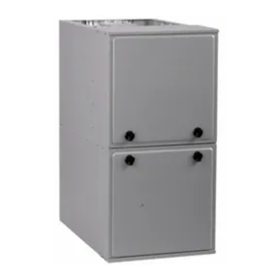
Page 8: Location
INSTALLATION INSTRUCTIONS Gas Furnace: N9MSB Location not be installed directly on any combustible material other than wood flooring (refer SAFETY CONSIDERATIONS). CAUTION be located close to the chimney or vent and attached to an air distribution system. Refer to Air Ducts section. be provided ample space for servicing and cleaning. - Page 9 INSTALLATION INSTRUCTIONS Gas Furnace: N9MSB Figure 3 Multipoise Orientations THE BLOWER IS LOCATED BELOW THE BURNER SECTION, AND CONDITIONED AIR IS DISCHARGED UPWARD. THE BLOWER IS LOCATED TO THE RIGHT OF THE BURNER SECTION, AND CONDITIONED AIR IS DISCHARGED TO THE LEFT. THE BLOWER IS THE BLOWER IS LOCATED TO THE LEFT...
-
Page 10: Location Relative To Cooling Equipment
INSTALLATION INSTRUCTIONS Gas Furnace: N9MSB Location Relative to Cooling CAUTION Equipment FURNACE CORROSION HAZARD The cooling coil must be installed parallel with, or on the Failure to follow this caution may result in furnace downstream side of the unit to avoid condensation in the heat damage. - Page 11 INSTALLATION INSTRUCTIONS Gas Furnace: N9MSB ONE OUTDOOR OPENING requires: =combined input other than fan-assisted other appliances in Btuh/hr a. 1 sq. in. (25.4 square mm)of free area per 3,000 Btuh (734 mm /kW) for combined input of all gas =combined input of all fan-assisted appliances in Btuh/hr appliances in the space per Table 3 and ACH = air changes per hour (ACH shall not exceed 0.60.) b.
- Page 12 INSTALLATION INSTRUCTIONS Gas Furnace: N9MSB Table 3 Minimum Free Area Required for Each Combustion Air Opening or Duct to Outdoors TWO OPENINGS OR TWO HORIZONTAL DUCTS SINGLE DUCT OR OPENING VERTICAL DUCTS (1 SQ. IN./2,000 BTUH) (1 SQ. IN./3,000 BTUH) (1 SQ.
-
Page 13: Condensate Trap
INSTALLATION INSTRUCTIONS Gas Furnace: N9MSB CONDENSATE TRAP Condensate Trap - - Upflow Orientation image in Figure 9. When the furnace is installed in the downflow orientation, the condensate trap must be relocated When the furnace is installed in the upflow position, it is not for proper condensate drainage. - Page 14 INSTALLATION INSTRUCTIONS Gas Furnace: N9MSB Downflow Trap Configuration Connect the new pressure switch tube from Loose Parts bag to Route tube through inducer port on front pressure switch. stand--offs to adjust position of the tube. Trim excess tube. Connect pressure switch tube to port on collector Install the two plugs box.
- Page 15 INSTALLATION INSTRUCTIONS Gas Furnace: N9MSB Figure 10 Unconverted Factory Configuration as viewed in the Horizontal Right Orientation Remove plug from If alternate vent position collector box. is required, loosen clamp DO NOT DISCARD. on inlet of vent elbow. Remove the screw that secures the trap to the collector box and remove trap.
- Page 16 INSTALLATION INSTRUCTIONS Gas Furnace: N9MSB Figure 11 Unconverted Factory Configuration as viewed in the Horizontal Left Orientation Remove the screw that secures the condensate trap to the collector box If alternate vent position and remove trap. is required, loosen clamp on vent elbow inlet.
- Page 17 INSTALLATION INSTRUCTIONS Gas Furnace: N9MSB Condensate Drain Connection a. The drains are not hard piped together, and b. There is an air gap at the point where the two drain lines meet or CAUTION c. All condensate piping is at least 1/2 in. PVC and there is a relief tee at the top of condensate drain piping as shown below: FROZEN AND BURST WATER PIPE HAZARD...
- Page 18 INSTALLATION INSTRUCTIONS Gas Furnace: N9MSB TIPS FROM CONTRACTORS: Contractors have found that 16. Open the spring clamp and insert the long end of the temporarily removing inducer assembly upflow adapter or the 1/2--in. CPVC pipe into the outlet stub on applications while performing the steps below, makes upflow the drain elbow.
- Page 19 INSTALLATION INSTRUCTIONS Gas Furnace: N9MSB Example of Field Drain Attachment Figure 14 Example of Field Drain Attachment Figure 13 (NOT ALLOWED) Evaporator Coil + + + + = Positive pressure Air gap here < + = Pressure lower than areas with + Open standpipe −...
-
Page 20: Installation
INSTALLATION INSTRUCTIONS Gas Furnace: N9MSB Example of Field Drain Attachment cont. Figure 17 Drain Trap Connection and Routing ATTACH ELBOW TO Evaporator Coil Ä Ä Ä Ä Ä Ä Ä Ä Ä FORMED END CONDENSATE TRAP Ä Ä Ä Ä Ä Ä Ä Ä Ä OF GROMMET CUT OFF FORMED END Open standpipe... -
Page 21: Upflow Installation
INSTALLATION INSTRUCTIONS Gas Furnace: N9MSB UPFLOW INSTALLATION Figure 20 Removing Bottom Closure Panel NOTE: The furnace must be pitched as shown in Figure 19 for proper condensate drainage. Figure 19 Furnace Pitch Requirements LEVEL 0-IN. (0 MM) TO 1/2-IN. (13 MM) MAX MIN 1/4-IN. -
Page 22: Downflow Installation
INSTALLATION INSTRUCTIONS Gas Furnace: N9MSB Leveling Legs (If Desired) Floor and Plenum Opening Figure 23 Dimensions In upflow position with side return inlet(s), leveling legs may be used. (See Figure 22) Install field--supplied, 5/16 x 1--1/2--in. (8 x 38 mm) (max) corrosion--resistant machine bolts, washers and nuts. - Page 23 INSTALLATION INSTRUCTIONS Gas Furnace: N9MSB Figure 24 Duct Flanges UPFLOW DOWNFLOW HORIZONTAL PERFORATED DISCHARGE DUCT 90° 90° FLANGE 120° 120° 120° A10493 Table 5 Opening Dimensions - - in. (mm) FURNACE PLENUM OPENING FLOOR OPENING CASING WIDTH APPLICATION IN. (mm) Upflow Applications on Combustible or Noncombustible Flooring 12- -11/16 21- -5/8...
-
Page 24: Horizontal Installation
INSTALLATION INSTRUCTIONS Gas Furnace: N9MSB HORIZONTAL INSTALLATION Furnace, Plenum, and Subbase Figure 25 Installed on a Combustible Floor NOTE: The furnace must be pitched forward as shown in Figure 19 for proper condensate drainage. WARNING FIRE, EXPLOSION, AND CARBON MONOXIDE POISONING HAZARD Failure to follow this warning could result in personal injury, death, or property damage. - Page 25 INSTALLATION INSTRUCTIONS Gas Furnace: N9MSB Figure 27 Suspended Furnace Installation COMBUSTION-AIR PIPE (SEE VENTING SECTION) 2-IN. (51 mm) ROLLOUT PROTECTION REQUIRED Install 12” x 22” (204 x 559 mm) sheet metal in front of and above the burner compartment area. The sheet metal MUST extend above the furnace casing by 1-in.
-
Page 26: Filter Arrangement
INSTALLATION INSTRUCTIONS Gas Furnace: N9MSB Supply Air Connections on the furnace. For side return use in the horizontal position, refer to Figure 31 and Figure 32. If both side and bottom For a furnace not equipped with a cooling coil, the outlet duct openings are used in Figure 31 and Figure 32, each opening shall be provided with a removable access panel. - Page 27 INSTALLATION INSTRUCTIONS Gas Furnace: N9MSB Table 7 Filter Media Pressure Drop (Clean) Versus Airflow - in. w.c. (Pa) Representative After-Market Filter Media* Factory-Accy Fiberglass* Pleated* 14 x 25 Filter Washable (1-in. / 2.5 cm) (1-in. / 2.5 cm) (2-in. / 5 cm) (1-in.
- Page 28 INSTALLATION INSTRUCTIONS Gas Furnace: N9MSB Downflow Return Air Horizontal Return Air Figure 29 Figure 32 Configurations and Restrictions Configurations and Restrictions HORIZONTAL TOP RETURN NOT PERMITTED FOR ANY MODEL SUPPLY RETURN *RETURN *HORIZONTAL LEFT BOTTOM RETURN NOT PERMITTED L10F033 FOR ALL MODELS. SEE TABLE BELOW. A14006 Upflow Return Air Configurations Figure 30...
- Page 29 INSTALLATION INSTRUCTIONS Gas Furnace: N9MSB External Filter Cabinet Configurations Figure 34 Accessory Bottom Filter Rack Figure 33 Accessory Side Filter Rack FURNACE FILTER FRAME FILTER TABS L10F031 DOOR L10F027 ⅜” ½” 2 ⅜” 1 ¼” (1 cm) (6 cm) (1.3 cm) (3 cm) TABS (TYP.)
-
Page 30: Air Ducts
INSTALLATION INSTRUCTIONS Gas Furnace: N9MSB Air Ducts GAS PIPING WARNING NOTICE FIRE OR EXPLOSION HAZARD Many states, provinces and localities are considering or Failure to follow this warning could result in personal in- have implemented standards and/or restrictions on duct jury, death, and/or property damage. - Page 31 INSTALLATION INSTRUCTIONS Gas Furnace: N9MSB WARNING A 1/8--in. (3 mm) NPT plugged tapping, accessible for test gauge connection, MUST be installed immediately upstream of gas supply connection to furnace and downstream of manual FIRE OR EXPLOSION HAZARD equipment shutoff valve. Piping should be pressure and leak tested in accordance with A failure to follow this warning could result in personal in- the current edition of the NFGC in the United States, local, and...
-
Page 32: Electrical Connections
INSTALLATION INSTRUCTIONS Gas Furnace: N9MSB WARNING Figure 37 Gas Entry Left Side Gas Entry. Gas Pipe Gas Pipe Grommet Required ELECTRICAL SHOCK AND FIRE HAZARD Grommet Required For Direct For Direct Vent Applications Vent Applications. Failure to follow this warning could result in personal injury, death, or property damage. -
Page 33: J--Box Installation
INSTALLATION INSTRUCTIONS Gas Furnace: N9MSB WARNING Use a separate, fused branch electrical circuit with a properly sized fuse or circuit breaker for this furnace. See Table 11 for wire size and fuse specifications. A readily accessible means of FIRE HAZARD electrical disconnect must be located within sight of the furnace. - Page 34 INSTALLATION INSTRUCTIONS Gas Furnace: N9MSB The J--Box cover, mounting bracket and screws are shipped in NOTE: If electrical entry through the furnace top panel is used, the loose parts bag included with the furnace. See Figure 40 a 7/8--in. (22 mm) hole must be drilled through the top panel. for J--Box mounting locations.
- Page 35 INSTALLATION INSTRUCTIONS Gas Furnace: N9MSB WARNING Field- -Supplied External Electrical Figure 42 Box on Furnace Casing FIRE, EXPLOSION, ELECTRICAL SHOCK, AND CARBON MONOXIDE POISONING HAZARD Failure to follow this warning could result in dangerous operation, personal injury, death, or property damage. Do no drill into blower shelf of furnace to route control wiring.
- Page 36 INSTALLATION INSTRUCTIONS Gas Furnace: N9MSB Alternate Power Supplies Power from an alternate power supply that non-sinusoidal may damage the furnace or cause erratic furnace operation. This furnace is designed to operate on a utility generated Contact alternate power supply manufacturer power which has a smooth sinusoidal waveform.
-
Page 37: Venting
INSTALLATION INSTRUCTIONS Gas Furnace: N9MSB Figure 44 Example of Single Stage Furnace Control for PSC Blower Motor HEAT COMPONENT TEST J2 JUMPER OFF- -DELAY TERMINAL 24- -V THERMOSTAT TERMINALS HUMIDIFIER TERMINAL (24- -VAC 0.5 AMP MAX) 24VAC TRANSFORMER 24- -VAC CONNECTIONS 3- -AMP FUSE COM/BLUE... - Page 38 INSTALLATION INSTRUCTIONS Gas Furnace: N9MSB ’apprêt et le ciment d’un manufacturier avec un système the current edition of National Fuel Gas Code NFPA 54/ANSI Z--223.1. In Canada, refer to CAN/CSA--B149.1 d’évacuation d’un manufacturier différent. An abandoned masonry chimney may be used as a raceway Bien suivre les indications du manufacturier lors de l’utilisation for properly insulated and supported combustion--air (when de l’apprêt et du ciment et ne pas utiliser ceux-ci si la date...
-
Page 39: Direct Vent / 2--Pipe System
INSTALLATION INSTRUCTIONS Gas Furnace: N9MSB combustion for a single pipe vent system. Refer to the “Air For NOTICE Combustion and Ventilation Section.” Provisions for adequate combustion, ventilation, and dilution air RECOMMENDED SUPPORT FOR VENT TERMINATIONS must be provided in accordance with: It is recommended that sidewall vent terminations of over 24 Non-Direct Vent (1-pipe) System inches (0.6 M) in length or rooftop vent terminations of over... - Page 40 INSTALLATION INSTRUCTIONS Gas Furnace: N9MSB Approved Combustion-Air and Vent Pipe, Fitting and Cement Materials (U.S.A. Installation) Table 13 MATERIALS 1. All pipe, fittings, primers*, and solvents* must conform to American National Standards Institute (ANSI) standards and Ameri- can Society for Testing and Materials (ASTM) standards or ULC S636 where required by code. 2.
- Page 41 INSTALLATION INSTRUCTIONS Gas Furnace: N9MSB NOTICE Figure 47 Vent Pipe Flush Showing Coupling ALIGN NOTCHES IN VENT PIPE COUPLING OVER STAND-- OFF ON ADAPTER. TORQUE LOWER CL AMP 15 LB--IN. WHEN RECOMMENDED SUPPORT VENT REMAINING VENT PIPE IS INSTALLED, TORQUE UPPER TERMINATIONS CL AMP TO 15 LB--IN.
- Page 42 INSTALLATION INSTRUCTIONS Gas Furnace: N9MSB Figure 48 Inside Corner Termination No operable windows, doors or Clearance distances for intakes of any type within the items greater than 3 feet shaded areas of Wall A and B. (1 meter ) away from the inside corner, refer to the For all other items, refer to the Inside Inside Corner Clearance...
-
Page 43: Ventilated Combustion Air
INSTALLATION INSTRUCTIONS Gas Furnace: N9MSB Direct Vent / 2- -Pipe System Termination Requirements for the Provinces of Alberta and Saskatchewan Direct vent (2--pipe) vent and combustion air pipes must terminate outside the structure. See Figure 65 for references to The Provinces of Alberta and Saskatchewan require a vent clearances required by National code authorities. - Page 44 INSTALLATION INSTRUCTIONS Gas Furnace: N9MSB Figure 49 Tee at Termination Outlet Figure 51 Vent Terminations OPTIONAL TERMINATION OPTIONAL BRACKET FOR 2-PIPE BRACKET TERMINATIONS COUPLING 12 IN. (305 MM) MIN. SEPARATION BETWEEN BOTTOM OF COMBUSTION AIR AND 12 IN. (305 MM) MIN. BOTTOM OF VENT.
- Page 45 INSTALLATION INSTRUCTIONS Gas Furnace: N9MSB Figure 52 Combustion Air and Vent Pipe Termination for Direct Vent (2- -Pipe) System Roof Termination (Preferred) Note: 36--in. separation between pairs of inlets only required for direct--vent systems Note: Vertical separation between At least 36 in. “A”...
- Page 46 INSTALLATION INSTRUCTIONS Gas Furnace: N9MSB Size the Vent and Combustion Air Pipes General Approved Two- Pipe Termination Fittings Vent and Allowable 1 1/2--in. 2--in. 2 1/2--in. 3--in. 4--in. Combustion Air Concentric Vent (38 mm) (51 mm) (64 mm) (76--mm) (102 mm) Pipe Diameters 1 1/2--in.
- Page 47 INSTALLATION INSTRUCTIONS Gas Furnace: N9MSB 2. Count the number of elbows for each pipe. b. If the Total Vent Length is longer than the Maximum 3. For each pipe, multiply the number of elbows by the Equivalent Vent Length for the diameter of pipe equivalent length for the type of elbow used.
- Page 48 INSTALLATION INSTRUCTIONS Gas Furnace: N9MSB Combustion Air and Vent Piping Insulation Guidelines NOTE: Use closed cell, neoprene insulation or equivalent. The vent pipe may pass through unconditioned areas. The amount of exposed pipe allowed is shown in Table 16. Slope vent pipe back to the 1.
- Page 49 INSTALLATION INSTRUCTIONS Gas Furnace: N9MSB Figure 58 Upflow Configurations Figure 59 Downflow Configurations UPFLOW LEFT -- VENT CONFIGURATION Representative drawing only, some models may vary in appearance. A11309 DOWNFLOW LEFT -- VENT CONFIGURATION Representative drawing only, some models may vary in appearance. A11311 UPFLOW RIGHT -- VENT CONFIGURATION DOWNFLOW RIGHT -- VENT CONFIGURATION...
- Page 50 INSTALLATION INSTRUCTIONS Gas Furnace: N9MSB Figure 60 Horizontal Left Configurations Figure 61 Horizontal Right Configurations HORIZONTAL LEFT -- VERTICAL VENT CONFIGURATION Representative drawing only, some models may vary in appearance. HORIZONTAL RIGHT -- VERTICAL VENT CONFIGURATION Representative drawing only, some models may vary in appearance. HORIZONTAL LEFT -- LEFT VENT CONFIGURATION Representative drawing only, some models may vary in appearance.
- Page 51 INSTALLATION INSTRUCTIONS Gas Furnace: N9MSB NOTES: 3. Pilot drill the screw holes for the adapter in the casing and attach the vent pipe adapter to the furnace with 1. Attach vent pipe adapter with gasket to furnace casing. sheet metal screws 2.
- Page 52 INSTALLATION INSTRUCTIONS Gas Furnace: N9MSB Hanger Spacing Material Diameter PVC Sch 40 SDR 21 & 26 CPVC Polypropylene 1 1/2--in. 3--ft. 2 1/2--ft. 3--ft. 3--ft. 3.25--ft. 38--mm 914--mm 762--mm 914--mm 914--mm 1000 mm 2--in. 3--ft. 3--ft. 3--ft. 3--ft. 3.25--ft. 51--mm 914--mm 914--mm 914--mm...
-
Page 53: Installing The Vent Termination
INSTALLATION INSTRUCTIONS Gas Furnace: N9MSB Slide assembled kit with rain shield REMOVED through hole in Figure 62 Combustion Air Pipe wall or roof flashing. NOTE: Do not allow insulation or other materials to accumulate inside of pipe assembly when installing it through hole. Disassemble loose pipe fittings. - Page 54 INSTALLATION INSTRUCTIONS Gas Furnace: N9MSB Two-Pipe and Single-Pipe Vent Termination (Direct Vent / Two-Pipe System ONLY) NOTE: Follow the instructions of the vent terminal When two or more furnaces are vented near each other, two vent terminations may be installed as shown in Figure 52, but manufacturer.
- Page 55 INSTALLATION INSTRUCTIONS Gas Furnace: N9MSB Figure 63 Crawl Space Vent Termination Ventilated Combustion Air intake pipe Pipe hangar 3” (76 mm) 12” (305 mm) Ventilated Combustion Air intake termination in crawl space CRAWL SPACE Figure 64 Attic Vent Termination Ventilated Combustion Air intake pipe Vent through roof flashing...
- Page 56 INSTALLATION INSTRUCTIONS Gas Furnace: N9MSB Figure 65 Direct Vent Termination Clearance 25- -24- -65- -2 NOTE: The following is based upon National codes for gas appliances, and is provided as a reference. Refer to Local codes which may supersede these standards and/or recommendations. (1 ) (2 ) Canadian Installations...
- Page 57 INSTALLATION INSTRUCTIONS Gas Furnace: N9MSB Figure 66 Other than Direct Vent Clearance - - Ventilated Combustion Air Option 25- -24- -65- -2 NOTE: The following is based upon National codes for gas appliances, and is provided as a reference. Refer to Local codes which may supersede these standards and/or recommendations. (1 ) (2 ) Canadian Installations...
- Page 58 INSTALLATION INSTRUCTIONS Gas Furnace: N9MSB Table 14 MAXIMUM EQUIVALENT VENT LENGTH - Feet (Meters) Note: Maximum Equivalent Vent Length (MEVL) does NOT include elbows or terminations Use Table 15 - - DEDUCTIONS FROM MEVL to determine allowable vent length for each application. Single Stage 92% - Feet/inches Unit Size 40,000...
-
Page 59: Maximum Equivalent Vent Length
INSTALLATION INSTRUCTIONS Gas Furnace: N9MSB Venting System Length Calculations The Total Equivalent Vent Length for EACH combustion air or vent pipe equals the length of the venting system, plus the equivalent length of elbows used in the venting system from Table 15. Standard vent terminations or factory accessory concentric vent terminations count for zero deduction. - Page 60 13.7 19.8 15.2 19.8 15.2 19.8 18.3 Design 10.7 13.7 13.7 15.2 12.2 Temp °C Not all families have these models Copyright 2018 International Comfort Products Lewisburg, TN 37091 USA Specifications subject to change without notice. 440 01 4104 07...
Need help?
Do you have a question about the C Series and is the answer not in the manual?
Questions and answers