
Related Manuals for ASROCK 4X4-V2000


Summary of Contents for ASROCK 4X4-V2000
- Page 1 4X4-V2000 User Manual Version 1.0 Published September 24, 2021 Copyright©2021 ASRockind INC. All rights reserved.
- Page 2 Version 1.0 Published September 24, 2021 Copyright©2021 ASRockind INC. All rights reserved. Copyright Notice: No part of this documentation may be reproduced, transcribed, transmitted, or translated in any language, in any form or by any means, except duplication of documentation by the purchaser for backup purpose, without written consent of ASRockind Inc.
- Page 3 ® The terms HDMI and HDMI High-Definition Multimedia Interface, and the HDMI logo are trademarks or registered trademarks of HDMI Licensing LLC in the United States and other countries. CAUTION: RISK OF EXPLOSION IF BATTERY IS REPLACED BY AN INCORRECT TYPE. DISPOSE OF USED BATTERIES ACCORDING TO THE INSTRUCTIONS.
-
Page 4: Table Of Contents
Contents 1 Introduction ............5 1.1 Package Contents ............5 1.2 Specifications ..............6 1.3 Motherboard Layout ............8 1.4 I/O Panel ................ 9 2 Installation ............10 2.1 Screw Holes ..............10 2.2 Pre-installation Precautions ........... 10 2.3 Installation of Memory Modules (SO-DIMM) ....11 2.4 Expansion Slots ............ -
Page 5: Introduction
Chapter 1: Introduction Thank you for purchasing ASRockind 4X4-V2000 motherboard, a reliable mother- board produced under ASRockind’s consistently stringent quality control. It delivers excellent performance with robust design conforming to ASRockind’s commitment to quality and endurance. In this manual, chapter 1 and 2 contain introduction of the motherboard and step- by-step guide to the hardware installation. -
Page 6: Specifications
1.2 Specifications Form Dimensions NUC 4.09" x 4.02" (104 x 102mm) Factor 4X4-V2000M (V2718, 8C, Max Speed up to 4.15GHz) Processor 4X4-V2000V (V2516, 6C, Max Speed up to System 3.95GHz) Chipset BIOS AMI SPI 128 Mbit Expansion 1 x M.2 (Key E, 2230) with PCIe x1, USB 2.0 and Slot CNVio for Wireless Technology Dual Channel DDR4 3200 MHz... - Page 7 USB (1x2.0 pitch header) Internal 1 x COM (RS-232/422/485) Connector Infinion SLB9670VQ2.0 1 x M.2 (KEY M, 2242/2260/2280) with PCIe x4 and SATA3 for SSD Storage *M.2 Key M 2280 (Supported by bracket) SATA 1 x SATA3.0 (6.0 Gb/s) Watchdog Output From Super I/O to drag RESETCON# Timer...
-
Page 8: Motherboard Layout
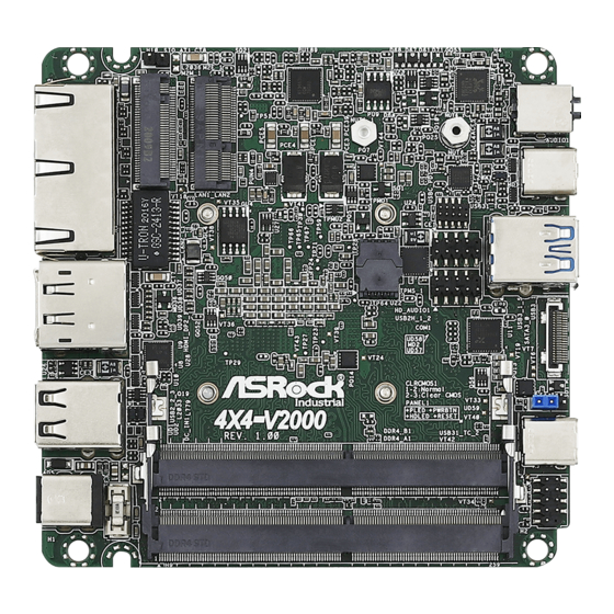
1.3 Motherboard Layout 1 : SIO_AT1 2 : M.2 Key-M Socket (M2M_1) 3 : M.2 Key-E Socket (M2E_1) 4 : Front Panel Audio Header 5 : USB2.0 Connector (USB2H_1_2) 6 : COM Port Header (RS232/422/485) 7 : SATA3 Port (SATA3_0) 8 : Clear CMOS Header (CLRCMOS1) 9 : System Panel Header (PANEL1) Back Side :... -
Page 9: I/O Panel
1.4 I/O Panel LAN RJ-45 Port (LAN1)* DC-In Jack (DC_IN1) LAN RJ-45 Port (LAN2)** USB 3.2 Gen2 Type-C Port (USB31_TC_2) HDMI Port (HDMI1) USB 3.2 Gen2 Ports (USB3_1_5) DisplayPort (DP2) USB 3.2 Gen2 Type-C Port (USB31_TC_1) USB 2.0 Ports (USB2_2_3) Audio Jack (AUDIO1) * There are two LED next to the LAN port. -
Page 10: Installation
Chapter 2: Installation Before you install the motherboard, study the configuration of your chassis to ensure that the motherboard fits into it. Make sure to unplug the power cord before installing or removing the motherboard. Failure to do so may cause physical injuries to you and damages to motherboard components. -
Page 11: Installation Of Memory Modules (So-Dimm)
2.3 Installation of Memory Modules (SO-DIMM) This motherboard provides two 204-pin DDR4 (Double Data Rate 4) SO-DIMM slots. Step 1. Align a SO-DIMM on the slot such that the notch on the SO-DIMM matches the break on the slot. 1. The SO-DIMM only fits in one correct orientation. It will cause permanent damage to the motherboard and the SO-DIMM if you force the SO-DIMM into the slot at incorrect orientation. -
Page 12: Expansion Slots
2.4 Expansion Slots (M.2 Slots) There are 2 M.2 slots on this motherboard. M.2 for SSD: 1 x M.2 (KEY M, 2242/2260/2280) with PCIe x4 and SATA3 for SSD. * M.2 Key M 2280 (Supported by bracket) M.2 for Wi-Fi: 1 x M.2 (Key E, 2230) with PCIe x1, USB 2.0 and CNVio for Wireless. -
Page 13: Jumpers Setup
2.5 Jumpers Setup The illustration shows how jumpers are setup. When the jumper cap is placed on pins, the jumper is “Short”. If no jumper cap is placed on pins, the jumper is “Open”. The illustration shows a 3-pin jumper whose pin1 and pin2 are “Short”... -
Page 14: Onboard Headers And Connectors
2.6 Onboard Headers and Connectors Onboard headers and connectors are NOT jumpers. Do NOT place jumper caps over these headers and connectors. Placing jumper caps over the headers and connectors will cause permanent damage of the motherboard! USB 2.0 Connector There is one USB 2.0 connector on this (9-pin USB2H_1_2) - Page 15 Front Panel Audio Header This is an interface for front panel audio cable that allows (9-pin HD_AUDIO1) convenient connection and (see p.8 No. 4) control of audio devices. Signal Signal Signal Signal Signal Name Name Name Name Name AGND LIN1_JD LIN2_JD 10 LIN1_L_ LIN1_R_...
- Page 16 Back Side: Power Button Header (PWR_BTN3) Fan Connector +12V (FAN1) FAN_SPEED FAN_SPEED_CONTROL...
-
Page 17: Uefi Setup Utility
Chapter 3: UEFI SETUP UTILITY 3.1 Introduction This section explains how to use the UEFI SETUP UTILITY to configure your system. The UEFI chip on the motherboard stores the UEFI SETUP UTILITY. You may run the UEFI SETUP UTILITY when you start up the computer. Please press <F2>... -
Page 18: Navigation Keys
3.1.2 Navigation Keys Please check the following table for the function description of each navigation key. Navigation Key(s) Function Description Moves cursor left or right to select Screens Moves cursor up or down to select items + / - To change option for the selected items <Enter>... -
Page 19: Advanced Screen
3.3 Advanced Screen In this section, you may set the configurations for the following items: CPU Configu- ration, Chipset Configuration, Storage Configuration, Super IO Configuration, ACPI Configuration, USB Configuration, Trusted Computing, MCTP Configuration and Se- rial Port Console Redirection. Setting wrong values in this section may cause the system to malfunction. -
Page 20: Cpu Configuration
3.3.1 CPU Configuration Cool ‘n‘ Quiet Use this item to enable or disable AMD’s Cool ‘n’ QuietTM technology. The default value is [Enabled]. Configuration options: [Enabled] and [Dis- ® abled]. If you install Windows OS and want to enable this function, please set this item to [Enabled]. -
Page 21: Chipset Configuration
3.3.2 Chipset Configuration Share Memory Configure the size of memory that is allocated to the integrated graphics processor when the system boots up. Onboard HD Audio Select [Enabled] or [Disabled] for the onboard HD Audio feature. Verb Table Select The default value is [Combo Jack]. Onboard LAN 1 This allows you to enable or disable the Onboard LAN 1. -
Page 22: Storage Configuration
3.3.3 Storage Configuration SATA Controller(s) Use this item to enable or disable the SATA Controller feature. SATA Mode Selection Use this to select SATA mode. The default value is [AHCI Mode]. AHCI (Advanced Host Controller Interface) supports NCQ and other new features that will improve SATA disk perfor- mance but IDE mode does not have these advantages. -
Page 23: Super Io Configuration
3.3.4 Super IO Configuration COM1 Configuration Use this to set parameters of COM1. Type Select Use this to select COM1 port type: [RS232], [RS422] or [RS485]. WDT Timeout Reset Use this to set the Watch Dog Timer. -
Page 24: Acpi Configuration
3.3.5 ACPI Configuration Suspend to RAM Use this item to select whether to auto-detect or disable the Suspend-to- RAM feature. Select [Auto] will enable this feature if the OS supports it. Onboard LAN Power On Use this item to enable or disable onboard LAN to turn on the system from the power-soft-off mode. -
Page 25: Usb Configuration
3.3.6 USB Configuration Legacy USB Support Use this option to select legacy support for USB devices. There are two configuration options: [Enabled] and [UEFI Setup Only]. The default value is [Enabled]. Please refer to below descriptions for the details of these two options: [Enabled] - Enables support for legacy USB. -
Page 26: Trusted Computing
3.3.7 Trusted Computing Security Device Support Enable or disable BIOS support for security device. -
Page 27: Hardware Health Event Monitoring Screen
3.4 Hardware Health Event Monitoring Screen In this section, it allows you to monitor the status of the hardware on your system, including the parameters of the CPU temperature, motherboard temperature, CPU fan speed, chassis fan speed, and the critical voltage. CPU_FAN1 Setting This allows you to set CPU_FAN1’s speed. -
Page 28: Security Screen
3.5 Security Screen In this section, you may set, change or clear the supervisor/user password for the system. Supervisor Password Set or change the password for the administrator account. Only the ad- ministrator has authority to change the settings in the UEFI Setup Utility. Leave it blank and press enter to remove the password. -
Page 29: Boot Screen
3.6 Boot Screen In this section, it will display the available devices on your system for you to config- ure the boot settings and the boot priority. Boot From Onboard LAN Use this item to enable or disable the Boot From Onboard LAN feature. Setup Prompt Timeout This shows the number of seconds to wait for setup activation key. - Page 30 CSM (Compatibility Support Module) Enable to launch the Compatibility Support Module. Please do not disable unless you’re running a WHCK test. If you are using Windows 8.1 64-bit and all of your devices support UEFI, you may also disable CSM for faster boot speed.
-
Page 31: Exit Screen
3.7 Exit Screen Save Changes and Exit When you select this option, it will pop-out the following message, “Save configuration changes and exit setup?” Select [OK] to save the changes and exit the UEFI SETUP UTILITY. Discard Changes and Exit When you select this option, it will pop-out the following message, “Discard changes and exit setup?”... -
Page 32: Software Support
Chapter 4: Software Support 4.1 Install Operating System ® ® This motherboard supports various Microsoft Windows operating systems: 10 64-bit. Because motherboard settings and hardware options vary, use the setup procedures in this chapter for general reference only. Refer your OS documentation for more information.
Need help?
Do you have a question about the 4X4-V2000 and is the answer not in the manual?
Questions and answers