Table of Contents
Advertisement
Quick Links
Advertisement
Table of Contents

Related Manuals for Telic NT910G

Summary of Contents for Telic NT910G
- Page 1 NT910G User Manual 31.01.2020 Release 1.0...
-
Page 2: Table Of Contents
Please note the following: ..............................6 Identification................................7 Physical Dimensions and Weight ........................7 Product Features and Technical Data ........................ 8 Telic Certified Accessories ............................9 3 Safety and Product Care ..................11 Audience and Intended Use ..........................12 Safety instructions ..............................12 General precautions .............................. - Page 3 NT910G User Manual - Telic AG Additional Software Configuration ........................23 5.8.1 Activating / Deactivating LTE Mode ........................ 23 5.8.3 Configuring specific frequency band ......................23 6 Installation of the modem ..................23 Where to install the modem ..........................23 6.1.1 Environmental conditions ............................
-
Page 4: General Terms And Conditions
We cannot be held responsible for material loss or personal injury that is due to non-compliance with the safety instructions. The warranty will be void in such circumstances. Telic reserves the right to change the included information without prior notice and does not take responsibility for errors in the document and/or for any missing information. -
Page 5: Conventions Used In This Manual
Related Documentation Please consult the download zone of the Telic AG website for additional documents related to LT910 E, such as AT command manuals. Note that such type of documents can be accessed online only after you have registered on our website and agreed with our terms of use. Please follow this link to register for a user account: http://www.telic.de/en/nda-reg-form... -
Page 6: Revision History
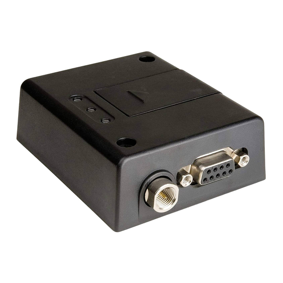
Table 2: Documentation Change Log 2 Product Description Overview The pictures below show the mechanical design of the NT910G Terminal along with the positions of the different connectors and mounting holes. The NT910G Terminal case is made of durable PC/ABS plastic. -
Page 7: Please Note The Following
NT910G User Manual - Telic AG Figure 1: Connector on rear side of the Terminal Figure 2: Connectors on front side of the Terminal PLEASE NOTE THE FOLLOWING: The terminal can be securely fitted into your application by using the mounting holes ▪... -
Page 8: Identification
Special DIN Rail Mounting Brackets (Art-nr. 12304 or Art-nr. 12305) is available as an accessory item which allows installation of the modem in industrial environments using DIN Rails. For more details of our accessories please check chapter 2.5 Telic Certified Accessories. Identification On the bottom of the device, you will find the type label. -
Page 9: Product Features And Technical Data
Figure 3: Drawing of the Terminal’s Housing Product Features and Technical Data NOTICE Telic AG may, at any time and without notice, make changes or improvements to the products and services offered and / or cease producing or commercializing them. NOTICE – Optional Features Features identified as “Optional”... -
Page 10: Telic Certified Accessories
NT910G User Manual - Telic AG B19(800) / B20(800) / B26(850) / B28(700) IP Protection IP40 1x (1,8/3 Volt) Size: 25 x 15 mm SIM Card Holder Mini-SIM, Form Factor: 2FF Hardware Features SIM Chip Option: Yes 1x Mobile communications 2x... - Page 11 NT910G User Manual - Telic AG Pg 10...
-
Page 12: Safety And Product Care
User Manual - Telic AG Table 4: Accessories List Please contact your distributor or Telic AG for availability or check Telic’s webpage http://www.telic.de. 3 Safety and Product Care This device has been designed in accordance with industrial standards, manufactured with utmost care using high-quality materials, and thoroughly tested. -
Page 13: Audience And Intended Use
NT910G User Manual - Telic AG If these instructions are ignored, Telic AG will not assume responsibility for any damages that are incurred. Telic AG may refuse warranty claims where evidence of product misuse is found. Please read the information in this section and the information in Section 6 Installation of the modem... -
Page 14: General Precautions
NT910G User Manual - Telic AG You should only use tools on components, modules or devices if they are disconnected from the power supply and the electric charge, which may still be stored in some components inside the device, has been discharged. -
Page 15: Sim Card Precautions
NT910G User Manual - Telic AG SIM card precautions Before handling the SIM card in your application, ensure that you are not charged with static electricity. Use proper precautions to avoid electrostatic discharges. When the SIM card hatch is opened, the SIM card connectors lie exposed under the SIM card holder. -
Page 16: Electrical Description
NT910G User Manual - Telic AG 4 Electrical Description The modem uses the following standard connectors: RJ11 6-way (power + 1 analogue input + 1 optional output) ▪ Mini USB (for data) – Also the power connector for the USB powered variant (optional) ▪... -
Page 17: Antenna Connector
NT910G User Manual - Telic AG Input 5 – 32V Active high control line used to switch off the terminal EMERG_OFF VIH > 5V, VIL < .5V Power off: t >1s Input 5 – 32V Positive edge triggered signal; used to switch on the modem VIH >... -
Page 18: Sim Card Reader
NT910G User Manual - Telic AG SIM card reader The Terminal is fitted with a SIM card reader designed for 1.8V and for 3V SIM cards. It is the flip-up type which is lockable in the horizontal position and is accessed through a removable panel. -
Page 19: Mini Usb Connector
The modem supports a standard USB 2.0 Full Speed slave interface to receive AT-commands as well as data transmissions. Drivers for Windows Desktop, Windows CE Embedded and instructions for Linux are available for download from the Telic AG website (for registered users only). Figure 5: Mini USB Type A/B connector for NT910 G 5 Operation... -
Page 20: Configuration Of The Bit Rate On The Serial Interface
NT910G User Manual - Telic AG The modem is fully operational after 8 seconds. Logging onto a network may take longer than this and is outside the control of the modem. The modem can be configured to start up at the time power is applied by permanently tying power connector signals TO_IN (pin 4) and VCC (pin 1) together. -
Page 21: Using Low Power Mode Of The Modem
NT910G User Manual - Telic AG EMERG_OFF to high level for t >1s on the RJ11 connector ▪ Turn off, or disconnect the power supply. ▪ Using low power mode of the modem The NT910 G terminal supports a special ultra-low power mode which can be activated or deactivated by sending dedicated AT commands, which are described further below in this section. -
Page 22: Disabling The Low Power Mode By User
NT910G User Manual - Telic AG 5.4.2 DISABLING THE LOW POWER MODE BY USER Set the DTR control line from Low to High. ▪ Low-power mode should be exited automatically. After sending DTR from Low to High, the ▪ module doesn’t save power, but the module is saving power again after setting DTR from High to Low. -
Page 23: Status Leds (One Yellow, One Red)
NT910G User Manual - Telic AG Status LEDs (one yellow, one red) The red and yellow Status LEDs are under control of GPIO1 and GPIO2 of the LE910 EU1 module inside the Terminal. They can be controlled via AT commands. The default status of these two LEDs is off. The... -
Page 24: Additional Software Configuration
NT910G User Manual - Telic AG Additional Software Configuration 5.8.1 ACTIVATING / DEACTIVATING LTE MODE The terminal is configured by default with 2G / LTE mode activated (AT+WS46=30). The following commands can be used to modify the usage of mobile network technologies (refer also to Section 3.2.26. -
Page 25: Gsm Signal Strength
NT910G User Manual - Telic AG 6.1.2 GSM SIGNAL STRENGTH The modem has to be placed in a way that ensures sufficient GSM signal strength. To improve signal strength, the antenna can be moved to another position. Signal strength may depend on how close the modem is to a radio base station. -
Page 26: Antenna
NT910G User Manual - Telic AG Securely attach the LT910 E Terminal modem to the host application using two 3mm diameter ▪ pan-head screws. Antenna 6.3.1 GENERAL The antenna is the component in your system that maintains the radio link between the network and the modem. -
Page 27: Possible Communications Disturbances
NT910G User Manual - Telic AG that the antenna cable is a high-quality, low-loss cable. Minimize the use of extension cables, connectors and adapters. Each additional cable, connector or adapter causes a loss of signal power. 6.3.5 POSSIBLE COMMUNICATIONS DISTURBANCES Possible communication disturbances include the following: Noise can be caused by electronic devices and radio transmitters.
Need help?
Do you have a question about the NT910G and is the answer not in the manual?
Questions and answers