Table of Contents
Advertisement
Advertisement
Table of Contents

Related Manuals for Acer Veriton M430


Summary of Contents for Acer Veriton M430
- Page 1 Acer Veriton M438G/M430G/M430 Service Guide PRINTED IN TAIWAN...
-
Page 2: Revision History
Revision History Please refer to the table below for the updates made on this service guide. Date Chapter Updates... - Page 3 Copyright Copyright © 2010 by Acer Incorporated. All rights reserved. No part of this publication may be reproduced, transmitted, transcribed, stored in a retrieval system, or translated into any language or computer language, in any form or by any means, electronic, mechanical, magnetic, optical, chemical, manual or otherwise, without...
- Page 4 Any Acer Incorporated software described in this manual is sold or licensed "as is". Should the programs prove defective following their purchase, the buyer (and not Acer Incorporated, its distributor, or its dealer) assumes the entire cost of all necessary servicing, repair, and any incidental or consequential damages resulting from any defect in the software.
- Page 5 Conventions The following conventions are used in this manual: SCREEN MESSAGES NOTE WARNING CAUTION IMPORTANT Denotes actual messages that appear on screen. Gives additional information related to the current topic. Alerts you to any physical risk or system damage that might result from doing or not doing specific actions.
-
Page 6: Fru Information
Service Guide. For ACER-AUTHORIZED SERVICE PROVIDERS, your Acer office may have a DIFFERENT part number code to those given in the FRU list of this printed Service Guide. You MUST use the list provided by your regional Acer office to order FRU parts for repair and service of customer machines. -
Page 7: Table Of Contents
Table of Contents System Tour Features Block Diagram System Components Front Panel Rear Panel Hardware Specifications and Configurations Power Management Function(ACPI support function) System Utilities CMOS Setup Utility Entering CMOS setup Navigating Through the Setup Utility Setup Utility Menus System Disassembly Disassembly Requirements Pre-disassembly Procedure Removing the Side Panel... -
Page 8: System Tour
System Tour Features Below is a brief summary of the computer’s many feature: NOTE: The features listed in this section is for your reference only. The exact configuration of the system depends on the model purchased. Operating System Microsoft Windows 7 Home Premium 64-bit •... -
Page 9: Serial Ata Controller
1 HDMI port and 1 D-sub port for Consumer model • 1 D-sub port and 1 DVI-D port for Commercial model • Need to measure VGA follow Acer SOP • Audio Chip : HD audio codec ALC662-VC HD codec 5.1 •... -
Page 10: Usb Ports
Controller: Realtek 8111E Gigabit Ethernet controller • RJ-45 Back panel port with Link/Activity LEDs • USB ports Ports Quantity: 14 (should reserve more header for front DB) • 6 ports for rear port • On-board: 4 2*5 headers • 4 ports for front daughter board 2 ports for internal card reader 2 ports for Daughter board (Aspire M5400/M3400 only) Connector Pin: standard Intel FPIO pin definition... -
Page 11: Power Supply
System BIOS Size: 8Mbit • AMI Kernel with Acer skin/copyright • Power supply 300W/500W in stable mode (Acer Assign System Power Unit) • Support 82+ PSU for EnergyStar 5.0 complaint • Design for RS880P+SB810 series chipset compatible system • Voltage design should be covered +5V, +3.3V, +12V, +5VSB, -12V (attention to 12V output capability) •... -
Page 12: Block Diagram
Block Diagram Chapter 1... -
Page 13: System Components
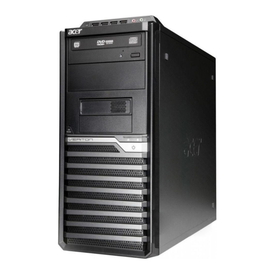
System Components This section is a virtual tour of the system’s interior and exterior components. Front Panel Component USB 2.0 ports Acer logo Optical drive(1) ODD activity indicator(1) Optical drive(2) ODD activity indicator(2) Smart Media card reader and XD(XD- Picture) slot... -
Page 14: Rear Panel
Rear Panel Component Power connector PS2 keyboard connector DVI port COM port USB 2.0 ports Microphone jack Speaker out jack Expansion slot(graphics card ect.) Lock Handle line-in jack RJ45 LAN port VGA Port System Fan PS2 mouse connector Fan aperture Chapter 1... -
Page 15: Hardware Specifications And Configurations
SB810 Audio controller ALC662-VC LAN controller Realtek 8111E Gigabit Ethernet controller HDD controller RS880P Specification AMI Kernel with Acer skin P01-A0 SPI ROM SMBIOS(DMI)2.4/DMI2.0 Support BBS spec 1st priority: HDD 2nd priority: CD-ROM 3th priority: LAN 4th priority: USB device Description Press while the system is booting to enter BIOS Setup Utility. -
Page 16: Memory Combinations
Memory Combinations Slot Memory Slot 1 1MB,2GB,4GB Slot 2 1MB,2GB,4GB Slot 3 1MB,2GB,4GB Slot 4 1MB,2GB,4GB Maximum System Memory Supported System Memory Item Memory slot number Support Memory size per socket Support memory type Support memory interface Support memory voltage Support memory module package Support to parity check feature Support to error correction code (ECC) feature No... -
Page 17: Environmental Requirements
SATA Interface Item SATA controller Number of SATA channel Support mode USB Port Item Universal HCI USB Class USB Connectors Quantity Environmental Requirements Item Specification Temperature Operating +5°C ~ +35°C Non-operating -20 ~ +60°C (Storage package) Humidity Operating 15% to 80% RH Non-operating 10% to 90% RH Vibration... -
Page 18: Power Management Function(Acpi Support Function)
Power Management Function(ACPI support function) Device Standby Mode Independent power management timer for hard disk drive devices(0-15 minutes,time step=1minute). • Hard Disk drive goes into Standby mode(for ATA standard interface). • Disable V-sync to control the VESA DPMS monitor. • Resume method:device activated (keyboard for DOS, keyboard &mouse for Windows. -
Page 19: System Utilities
System Utilities CMOS Setup Utility CMOS setup is a hardware configuration program built into the system ROM, called the complementary metal- oxide semiconductor (CMOS) Setup Utility. Since most systems are already properly configured and optimized, there is no need to run this utility. You will need to run this utility under the following conditions. When changing the system configuration settings •... -
Page 20: Entering Cmos Setup
Entering CMOS setup Turn on the server and the monitor. If the server is already turned on, close all open applications, then restart the server. During POST, press Delete. If you fail to press Delete before POST is completed, you will need to restart the server. The Setup Main menu will be displayed showing the Setup’s menu bar. -
Page 21: Setup Utility Menus
Setup Utility Menus The Setup Main menu includes the following main setup categories. Parameter Description Product Information This page shows the relevant information of the main board Standard CMOS Features This setup page includes all the items in standard compatible BIOS Advanced BIOS Features This setup page includes all the items of Award special enhanced features Advanced Chipset Features... -
Page 22: Product Information
Product Information The Product Information menu displays basic information about the system. These entries are for your reference only and are not user-configurable. Parameter Description Processor Type Type of CPU installed on the system. Processor Speed Speed of the CPU installed on the system. System Memory Total size of system memory installed on the system. -
Page 23: Standard Cmos Features
Standard CMOS Features Parameter Description System Date Set the date following the weekday-month-day-year format. System Time Set the system time following the hour-minute-second format. Halt On Determines whether the system will stop for an error during the POST. Chapter 2 Option All, But Keyboard No Errors... -
Page 24: Advanced Bios Feature
Advanced BIOS Feature Parameter Description Quick Boot Allows you to decrease the time it takes to boot the computer by shortening or skipping certain standard booting process. Quiet Boot When enabled, the BIOS splash screen displays during startup. When disabled, the diagnostic screen displays during startup. 1st/2nd/3rd/4th Boot Device Specifies the boot order from the available devices. -
Page 25: Advanced Chipset Features
Advanced Chipset Features Parameter Description AMD Cool’n’ Quiet When enabled, this feature allows the OS to reduce power consumption. When disabled, the system operates at maximum CPU speed. AMD-V Enables or disables the Virtualization Technology (VT) availability. If enabled, a virtual machine manager (VMM) can utilize the additional hardware virtualization capabilities provided by this technology. -
Page 26: Integrated Peripherals
Integrated Peripherals Parameter Onboard SATA Controller Onboard SATA Mode Onboard USB Controller Legacy USB Support USB Storage Emulation Onboard Graphics Controller Onboard Graphics Mode Onboard Audio Controller Onboard LAN Controller Onboard LAN Option ROM Onboard Floppy Controller Serial Port1 Address Serial Port1 Mode Serial Port2 Address Serial Port2 Mode... -
Page 27: Power Management Setup
Power Management Setup Parameter Description ACPI Suspend Mode Select an ACPI state. Deep power off mode Select the Deep power off Mode Power On by RTC Alarm Enables or Disables to wake up the system by RTC Alarm Function Power On by PCIE Devices Enables or disables to wake up the system from a power saving mode through an event on PCI Express device. -
Page 28: Pc Health Status
PC Health Status Parameter Description system Shutdown Select the system Shutdown Temperature Temperature CPU Shutdown Temperature Select the system Shutdown Temperature Smart FAN Enables or disables the smart system fan control function. Option Enabled Disabled Enabled Disabled Enabled Disabled Chapter 2... -
Page 29: Frequency/Voltage Control
Frequency/Voltage Control Parameter Description Spread Spectrum Enables or disables the reduction of the mainboard’s EMI. Note: Remember to disable the Spread Spectrum feature if you are overclocking. A slight jitter can introduce a temporary boost in clock speed causing the overclocked processor to lock up. Chapter 2 Option Enabled... -
Page 30: Bios Security Features
BIOS Security Features Parameter Description Supervisor Password Indicates the status of the supervisor password. User Password Indicates the status of the user password. Change Supervisor Supervisor password prevents unauthorized access to the BIOS Setup Utility. Password Press Enter to change the Supervisor password. Setting a supervisor password Use the up/down arrow keys to select Change Supervisor Password menu then press Enter. -
Page 31: Load Default Settings
Load Default Settings The Load Default Settings menu allows you to load the default settings for all BIOS setup parameters. Setup defaults are quite demanding in terms of resources consumption. If you are using low-speed memory chips or other kinds of low-performance components and you choose to load these settings, the system might not function properly. -
Page 32: Save And Exit Setup
Save & Exit Setup The Save & Exit Setup menu allows you to save changes made and close the Setup Utility. Chapter 2... -
Page 33: Exit Without Saving
Exit Without Saving The Exit Without Saving menu allows you to discard changes made and close the Setup Utility. Chapter 2... -
Page 34: System Disassembly
System Disassembly This chapter contains step-by-step procedures on how to disassemble the desktop computer for maintenance and troubleshooting. Disassembly Requirements To disassemble the computer, you need the following tools: Wrist grounding strap and conductive mat for preventing electrostatic discharge • Flat-blade screwdriver •... -
Page 35: Pre-Disassembly Procedure
Pre-disassembly Procedure Before proceeding with the disassembly procedure, perform the steps listed below: Turn off the system and all the peripherals connected to it. Unplug the power cord from the power outlets. Unplug the power cord from the system. Unplug all peripheral cables from the system. Place the system unit on a flat, stable surface. -
Page 36: Removing The Side Panel
Removing the Side Panel Remove the two screws located on the rear edge of the side panel. The firstly use two fingers to Press the lock handle toward the arrowhead of the direction until the lock handle no moving,then use other hand to Lift the side panel away from the chassis and put it aside. Chapter 3... -
Page 37: Removing The Front Bezel
Removing the Front Bezel Remove the side panel. Refer to the previous section for instructions. Release the front bezel from the chassis interior. Pull the bezel away from the chassis. Chapter 3... -
Page 38: Removing The Heat Sink Fan Assembly
Removing the Heat Sink Fan Assembly WARNING:The heat sink becomes very hot when the system is on. NEVER touch the heat sink with any metal or with your hands. Disconnect the fan cable from the mainboard. Use a long-nosed screwdriver to loosen the four screws on the heat sink, in the order as shown below. Chapter 3... - Page 39 Lift the heat sink fan assembly away from the mainboard. Use an alcohol pad to wipe off the thermal grease from both the heat sink and the processor. Chapter 3...
-
Page 40: Removing The Processor
Removing the Processor IMPORTANT:Before removing a processor from the mainboard, make sure to create a backup file of all important data. WARNING:The processor becomes very hot when the system is on. Allow it to cool off first before handling. Release the load lever. Lift the load lever and load plate to the fully open. -
Page 41: Removing The Memory Modules
Removing the Memory Modules IMPORTANT:Before removing any DIMM from the memory board, make sure to create a backup file of all important data. Press the holding clips on both sides of the DIMM slot outward to release the DIMM(1,2). Gently pull the DIMM upward to pull it away from the M/B(3). Chapter 3... -
Page 42: Removing The Vga Card
Removing the VGA Card Remove the PCI fixer. Use One finger to Press the clip. Gently pull the card to remove it from the mainboard. Chapter 3... -
Page 43: Removing The Hard Disk Drive
Removing the Hard Disk Drive Disconnect the data and power cables from the rear of the optical drive. Disconnect the other end of the data cable from the mainboard. Remove the HDD bracket. Use two fingers to press the HDD bracket then lift the bracket up. Chapter 3... - Page 44 Take out the HDD module Use a hand to open out the HDD bracket until the hook of HDD bracket away from the HDD screw bore. then use other hand to take out the HDD module. Chapter 3...
-
Page 45: Removing The Optical Drive
Removing the Optical Drive Disconnect the data and power cables from the rear of the optical drive. Disconnect the other end of the data cable from the mainboard. Slide two lock handle toward the left(1) until the lock hnadle no removing(2). Chapter 3... - Page 46 Push the rear of the optical drive. take out the slave ODD. Use the same method to take out master ODD. Chapter 3...
-
Page 47: Remove System Fan
Removing System FAN Remove System FAN cable from M/B. Release four screws according to the following picture. Take off the system fan from chassis. Chapter 3... -
Page 48: Removing The Power Supply
Removing the Power Supply Disconnect the 4-pin and 24-pin power supply cables from the mainboard. Remove the four screw that secures the power supply to the chassis. Lift the power supply module out of the chassis. Chapter 3... -
Page 49: Removing The Obr Cable And Intrusion Alarm Cable
Removing the OBR Cable and Intrusion Alarm Cable Disconnector the OBR cable and intrusion alarm from the motherboard. Release the retention tabs from the chassis interior. Pull the OBR assembly from the chassis. Chapter 3... - Page 50 Removing the two screws.then take out the intrusion alarm assembly. Chapter 3...
-
Page 51: Removing The Card Reader
Removing the Card Reader Disconnector the card resder cable from the motherboard,then release the cable from the clip. Slide the lock handle as show below. Pull the card reader away from the bracket. Chapter 3... -
Page 52: Removing The Internal Speaker
Removing the Internal Speaker Disconnector the speaker cable from the motherboard. Slide the lock handle as show below. Pull the internal speaker away from bracket. Chapter 3... -
Page 53: Removing The Mainboard
Removing the Mainboard Disconnect the power switch/LED/Audio/ USB cable from the mainboard. Remove the eight screws that secure the mainboard to the chassis. Note: Circuit boards >10 cm² has been highlighted with the yellow rectangle as above image shows. Please detach the Circuit boards and follow local regulations for disposal. Chapter 3... - Page 54 Lift the board from the chassis. Punching in IO Shield then you can remove it. Remove the RTC battery. Note: RTC battery has been highlighted with the yellow circle as above image shows.Please detach the RTC battery and follow local regulations for disposal. Chapter 3...
-
Page 55: Removing Other Side Pannel
Removing Other Side Pannel Remove the two screws located on the rear edge of the side panel. Lift the side panel away from the server. Chapter 3... -
Page 56: Removing The Front I/O And Usb Assembly
Removing the Front I/O and USB Assembly Release the cable from clip. Release the five locking tabs from the chassis interior. Lift the front I/O and USB cover from the chassis. Chapter 3... - Page 57 Removing the screws from the chassis. Lift the front I/O and USB assembly away from chassiss. Chapter 3...
-
Page 58: Removing The Power Switch And Led Cable Assembly
Removing the Power Switch and LED Cable Assembly Release the locking tabs from the chassis interior. Pull the power switch and LED cable assembly from the chassis. Chapter 3... -
Page 59: System Troubleshooting
This chapter provides instructions on how to troubleshoot system hardware problems. Hardware Diagnostic Procedure IMPORTANT:The diagnostic tests described in this chapter are only intended to test Acer products. Non- Acerproducts, prototype cards, or modified options can give false errors and invalid systemresponses. -
Page 60: System Check Procedures
Verify that components are properly seated. Verify that all cable connectors inside the system are firmly and correctly attached to their appropriate connectors. Verify that all components are Acer-qualified and supported. 10. Replace the system covers. 11. Power on the system. -
Page 61: Beep Codes
Beep Codes Beep codes are used by the BIOS to indicate a serious or fatal error to the end user. Beep codes are used when an error occurs before the system video has been initialized. Beep codes will be generated by the system board speaker, commonly referred to as the PC speaker. -
Page 62: Bootblock Initialization Code Checkpoints
Checkpoints A checkpoint is either a byte or word value output to I/O port 80h.The BIOS outputs checkpoints throughout bootblock and Power-On Self Test (POST) to indicate the task the system is currently executing. Checkpoint sare very useful in aiding software developers or technicians in debugging problems that occur during the pre- boot process. - Page 63 Checkpoint Restore CPUID value back into register. Give control to BIOS POST (ExecutePOSTKernel). See POST Code Checkpoints section of document for more information. System is waking from ACPI S3 state. E1-E8 EC- OEM memory detection/configuration error. This range is reserved for chipset vendors & system manufacturers.
-
Page 64: Bootblock Recovery Code Checkpoints
Bootblock Recovery Code Checkpoints The Bootblock recovery code gets control when the BIOS determines that a BIOS recovery needs to occur because the user has forced the update or the BIOS checksum is corrupt. The following table describes the type of checkpoints that may occur during the Bootblock recovery portion of the BIOS. NOTE: Checkpoints may differ between different platforms based on system configuration. -
Page 65: Bios Recovery
BIOS Recovery Copy the target BIOS rom file to a USB disk. Rename the target BIOS to “amiboot.rom”.Plug the USB disk to computer that you want to recovery the system BIOS. Power on the system, BIOS recovery will be done. Wait for about 3 minutes the system will reboot automatically after flash update completed successfully. -
Page 66: Jumper And Connector Information
Chapter 5 Jumper and Connector Information M/B Placement Chapter 5... - Page 67 Label CPU Socket PWR2 DIMM PWR1 C_INTRUSIO F_USB1~3 CLR_CMOS HBIOS_WP SPDIF_OUT AUDIO PCIE_1X1 PCI-E1_16X Description AM3 938 socket for CPU Power connector CONN,DIMM,DDRIII, 1.5V,Blu,1mm,G/ F,G,DIP-240 Trusted platform module interface header M/B main power connector Chassis intrusion alarm header Card reader USB headers Clear CMOS jumpers SPDIF out header...
-
Page 68: Jumper Setting
Jumper Setting The section explains how to set jumper for correct configuration of the mainboard. Setting Jumper Use the motherboard jumpers to set system configuration options. Jumpers with more numbered. When setting the jumpers, ensure that the jumper caps are Internal header pin definition Jumper/Header Name CPU_FAN (3 PIN) - Page 69 Jumper/Header Name F_USB1, F_USB2, F_USB3, F_USB4 F_AUDIO Function System Recover HEADER Yellow is symbol, Red is Pin 1 of symbol. FRONT USB HEADER (2X5) Yellow is symbol, Red is Pin 1 of symbol. FRONT PANEL AUDIO HEADER (2X5) Yellow is symbol, Red is Pin 1 of symbol. Definition 1:SYS_RECOVER 2: GND...
- Page 70 Jumper/Header Name F_1394 F_PANEL Chapter 5 Function FRONT 1394 HEADER Yellow is symbol, Red is Pin 1 of symbol. Front panel header Yellow is symbol, Red is Pin 1 of symbol. TPM Header Definition 1. 1394_TPA0P_C 2. 1394_TPA0N_C 3. GND 4.
- Page 71 Jumper/Header Name SPEAKER Function Printer Header Yellow is symbol, Red is Pin 1 of symbol. Audio internal speaker header Yellow is symbol, Red is Pin 1 of symbol. Definition 1: STRBJ 2: AFDJ 3: PRP_D0 4: PRERRJ 5:PRP_D1 6: INITJ 7: PRP_D2 8: SLINJ 9: PRP_D3...
- Page 72 Jumper/Header Name SPDIF_OUT, SPDIF_OUT1 COM2 COM2 Header_2X5_K10 @Commercial Chapter 5 Function Yellow is symbol, Red is Pin 1 of symbol. Yellow is symbol, Red is Pin 1 of symbol. Definition 1: VCC (5V_SYS) 2: KEY 3: A_SPDIF_OUT1 4: GND 1. JDCD2J 2.
- Page 73 USB CONNECTORS (Stacked)(Black) USB_X4 "11,21,31,41" "45,46,47,48, 49,50" Signal Name VCC_USB1 USBP3N_R USBP3P_R Ground USBP2N_R USBP2P_R Ground USBP5N_R USBP5P_R Ground USBP4N_R USBP4P_R Ground Ground Chapter 5...
- Page 74 11.2.2LAN-USB_X2 "1, 5" "4, 8" "23,24,25,26, 27,28,29,30" NOTE: Pins 9-18 for RJ-45 LAN Jack pin definition, 19-22 for LAN LED definition Chapter 5 Signal Name VCC_USB0 (5V) USBP7N_R USBP6N_R USBP6N_R USBP6P_R Ground AVDD18 MDI0+ MDI0- MDI1+ MDI1- MDI2+ MDI2- MDI3+ MDI3- ACT_LED LAN_LINK_LED...
- Page 75 Audio Back Panel Connectors AUDIO1A (MIC) AUDIO1B (Line in) AUDIO1C (Line out) IDE / SATA 40-pin (2x20) IDE Headers IDERST PIDE_D7 PIDE_D 6 PIDE_D 5 PIDE_D 4 PIDE_D 3 PIDE_D 2 PIDE_D 1 PIDE_D 0 Ground PIDE_DREQ PIDE_IOWJ PIDE_IORJ PIDE_RDY PIDE_PACKJ PIDE_IRQ Signal Name...
- Page 76 PIDE_A1 PIDE_A0 PIDE_CS1J PATA_LEDJ 1x7-pin SATA Headers HDMI Chapter 5 Signal Name PD_DMA66 PIDE_A2 PIDE_CS3J Ground Signal Name SATA_TX0+_ SATA_TX0-_C SATA_RX0-_C SATA_RX0+_C Signal Name NC (5V_VGA) HSYNC VSYNC Signal Name HDMI_TXDP2_C HDMI_TXDN2_C HDMI_TXDP1_C HDMI_TXDN1_C Signal Name...
- Page 77 DVI-D Signal Name HDMI_TXDP0_C HDMI_TXDN0_C HDMI_TXCP_C HDMI_TXCN_C HDMI_DDCCLK_C HDMI_DDCDATA_C 5V_HDMI_C HP_DET_C Signal Name DVI_TXDN2_C DVI_TXDP2_C HDMI_DDCCLK_C HDMI_DDCDATA_C DVI_TXDN1_C DVI_TXDP1_C Signal Name KB_DA KBVCC (5V_DUAL) KB_CK MS_DA Signal Name 5V_HDMI_C HP_DET_C DVI_TXDN0_C DVI_TXDP0_C DVI_TXCP_C DVI_TXCN_C Signal Name KBVCC (5V_DUAL) MS_CK Chapter 5...
- Page 78 5,10,11 Chapter 5 Signal Name JDCD1J JSIN1 JSOUT1 JDTR1J JDSR1J JRTS1J JCTS1J JRI1J...
-
Page 79: Fru (Field Replaceable Unit) List
To scrap or to return the defective parts, follow the local government ordinance or regulations on • how to dispose it properly, or follow the rules set by your regional Acer office on how to return it. This document will be updated as more information about the FRU list becomes available. -
Page 80: Veriton M438G/M430G/M430 Exploded Diagram
Veriton M438G/M430G/M430 Exploded Diagram NOTE: This section will be updated when more information becomes available. ITEM NAME CHASSIS LINE-CLIP USB-SHIELD NUT 6-32# USB-SHIELDING USB PCB MODULE SIDE FOOT RUBBER RIGHT SIDE PLATE LED/SEITCH HOLDER CD-ROM CARD READER DEVICE OBR HOLDER PLASTIC FOOT CD-ROM LOCK SLIDE FDD-LOCK-SLIDE... -
Page 81: Veriton M438G/M430G/M430 Fru List
Veriton M438G/M430G/M430 FRU List Category MB Kit Chassis Bezel Nameplate Dust filter CPU Cooler System Fan Chapter 6 Description MB Kit FRS880F commercial HM081 VM410 for HM081 Veriton M4 series Dust filter HM081, V-2 Flammability Rating Fan Cooler K8_M2 FXC PKP482 Fan8025 Fan Cooler K8_M2 AVC Z7UB008 AVC fan7015 Fan Cooler AMD AM2 HS080 with duct Cooler AMD AVC Z8UH408002 (for 125W/140W) - Page 82 Category Memory Description AMD Phenom II 955 AMD Phenom II B95 AMD Phenom II 740 AMD Phenom II 720 AMD Phenom II B75 AMD Phenom II 555 AMD Phenom II 550 AMD Phenom II B55 AMD Athlon II x4 640 AMD Athlon II x4 635 AMD Athlon II x4 605e AMD Athlon II x3 445...
- Page 83 Category Chapter 6 Description DDRIII 1333MHz 2GB DDRIII 1333MHz 2GB DDRIII 1333MHz 4GB DDRIII 1333MHz 4GB DDRIII 1333MHz 4GB DDRIII 1333MHz 4GB HDD HGST 3.5" 7200rpm 160GB HDT721016SLA380 Saturn SATA II LF F/W:31B HDD HGST 3.5" 7200rpm 160GB Jupiter HDD HGST 3.5" 7200rpm 320GB HDT721032SLA380 Saturn SATA II LF F/W:31B HDD HGST 3.5"...
- Page 84 Category Description ODD HLDS DVD-ROM HH 16X DH20N LF+HF Black Bezel SATA w/Win7 ODD PLDS DVD-ROM HH DL 16X DH-16D5SH LF+HF Black Bezel SATA w/Win7 ODD TSST DVD-ROM w/Win7 ODD HLDS Super-Multi DRIVE HH 16X GH41N Black Bezel SATA HF + Win 7 ODD PLDS Super-Multi DRIVE HH 16X DH-16AASH Black Bezel SATA HF+Win7 ODD TSST Super-Multi with LF...
- Page 85 Category Card Reader Modem WLAN Power Supply Chapter 6 Description 288-1E127-110AC HD5450 512MB SDDR 3 (64BITS) HYNIX DUAL DVI PASSIVE W/ATX BKT ROHS 288-1E145-A01AC HD5450 512MB SDDR 3 (64BITS) SAMSUNG DVI HDMI W/LP BKT ROHS 288-1E145-001AC HD5450 512MB SDDR 3 (64BITS) SAMSUNG DVI HDMI VGA W/ATX BKT ROHS 288-1E145-101AC HD5450 512MB SDDR 3 (64BITS) HYNIX DVI HDMI VGA W/ATX BKT ROHS...
- Page 86 FR 300W (16L) EuP 82+ FR 300W (16L) EuP 82+ Internal Speaker_3.5V2 Mono (Plug on HD audio header) Neosonica Speaker Acer logo /LF /0810 / 9M-20A200-000 Neosonica Speaker USB with new color AC-MT-018 Sony FDD 1.44M 3.5" Black RoHS TPM module...
- Page 87 Category Keyboard Chapter 6 Description Logitech 0810_USB Optical mouse USB M-UAY-ACR2 Lite-On PS2 optical mouse PS2 SM-9620 Lite-On USB optical USB SM-9625 Lite-on Optical mouse USB SM-9625S with new color AC- MT-018 Chicony RF2.4G mouse RF2.4G MG-0766 Chicony 2.4G Dangle Receiver external receiver Keyboard CHICONY KG-0766 RF2.4 Standard 104KS Black US w/o Aspire logo Keyboard CHICONY KG-0766 RF2.4 Standard 104KS Black...
- Page 88 Category Description Keyboard CHICONY KG-0766 RF2.4 Standard 105KS Black Icelandic w/o Aspire logo Keyboard CHICONY KG-0766 RF2.4 Standard 105KS Black Norwegian w/o Aspire logo Keyboard CHICONY KG-0766 RF2.4 Standard 104KS Black Hebrew w/o Aspire logo Keyboard CHICONY KG-0766 RF2.4 Standard 105KS Black Polish w/o Aspire logo Keyboard CHICONY KG-0766 RF2.4 Standard 105KS Black Slovenian w/o Aspire logo...
- Page 89 Category Chapter 6 Description Keyboard CHICONY KB-0759 PS/2 Standard 104KS Black Traditional Chinese w/o eKey Keyboard CHICONY KB-0759 PS/2 Standard 104KS Black Simplified Chinese w/o eKey Keyboard CHICONY KB-0759 PS/2 Standard 104KS Black US International w/o eKey Keyboard CHICONY KB-0759 PS/2 Standard 104KS Black Arabic/English w/o eKey Keyboard CHICONY KB-0759 PS/2 Standard 104KS Black Thailand w/o eKey...
- Page 90 Category Description Keyboard CHICONY KB-0759 PS/2 Standard 104KS Black Russian w/o eKey Keyboard CHICONY KB-0759 PS/2 Standard 105KS Black Hungarian w/o eKey Keyboard CHICONY KB-0759 PS/2 Standard 104KS Black Greek w/o eKey Keyboard CHICONY KB-0759 PS/2 Standard 105KS Black Danish w/o eKey Keyboard CHICONY KB-0759 PS/2 Standard 104KS Black Czech w/o eKey Keyboard CHICONY KB-0759 PS/2 Standard 105KS Black...
- Page 91 Category Chapter 6 Description Keyboard LITE-ON SK-9620 PS/2 Standard 104KS Black Arabic/English w/o eKey Keyboard LITE-ON SK-9620 PS/2 Standard 104KS Black Thailand w/o eKey Keyboard LITE-ON SK-9620 PS/2 Standard 105KS Black Spanish w/o eKey Keyboard LITE-ON SK-9620 PS/2 Standard 105KS Black Portuguese w/o eKey Keyboard LITE-ON SK-9620 PS/2 Standard 105KS Black Canadian French w/o eKey...
- Page 92 Category Description Keyboard LITE-ON SK-9620 PS/2 Standard 105KS Black Danish w/o eKey Keyboard LITE-ON SK-9620 PS/2 Standard 104KS Black Czech w/o eKey Keyboard LITE-ON SK-9620 PS/2 Standard 105KS Black Romanian w/o eKey Keyboard LITE-ON SK-9620 PS/2 Standard 105KS Black Turkish w/o eKey Keyboard LITE-ON SK-9620 PS/2 Standard 105KS Black Spanish Latin w/o eKey Keyboard LITE-ON SK-9620 PS/2 Standard 105KS Black...
- Page 93 Category Chapter 6 Description Keyboard CHICONY KU-0760 USB Standard 107KS Black Brazilian Portuguese w/o eKey Keyboard CHICONY KU-0760 USB Standard 109KS Black Japanese w/o eKey Keyboard CHICONY KU-0760 USB Standard 105KS Black German w/o eKey Keyboard CHICONY KU-0760 USB Standard 105KS Black Italian w/o eKey Keyboard CHICONY KU-0760 USB Standard 105KS Black French w/o eKey...
- Page 94 Category Description Keyboard CHICONY KU-0760 USB Standard 105KS Black Spanish Latin w/o eKey Keyboard CHICONY KU-0760 USB Standard 105KS Black Turkish-Q w/o eKey Keyboard CHICONY KU-0760 USB Standard 105KS Black Arabic/French w/o eKey Keyboard CHICONY KU-0760 USB Standard 104KS Black Kazakh w/o eKey Keyboard CHICONY KU-0760 USB Standard 104KS Black Turkmen w/o eKey...
- Page 95 Category Chapter 6 Description Keyboard LITE-ON SK-9625 USB Standard 105KS Black German w/o eKey Keyboard LITE-ON SK-9625 USB Standard 105KS Black Italian w/o eKey Keyboard LITE-ON SK-9625 USB Standard 105KS Black French w/o eKey Keyboard LITE-ON SK-9625 USB Standard 105KS Black Swedish w/o eKey Keyboard LITE-ON SK-9625 USB Standard 105KS Black UK w/o eKey...
- Page 96 Category Description Keyboard LITE-ON SK-9625 USB Standard 105KS Black Arabic/French w/o eKey Keyboard LITE-ON SK-9625 USB Standard 104KS Black Kazakh w/o eKey Keyboard LITE-ON SK-9625 USB Standard 104KS Black Turkmen w/o eKey Keyboard LITE-ON SK-9625 USB Standard 105KS Black Nordic w/o eKey Keyboard LITE-ON SK-9625 USB Standard 105KS Black Czech/Slovak w/o ekey Keyboard LITE-ON SK-9625 USB Standard 105KS Black...
Need help?
Do you have a question about the Veriton M430 and is the answer not in the manual?
Questions and answers