
Related Manuals for Acer EZ1601-01


Summary of Contents for Acer EZ1601-01
- Page 1 EZ1600/EZ1601 Service Guide Service guide files and updates are available on the ACER/CSD web; for more information, please refer to http://csd.acer.com.tw PRINTED IN TAIWAN...
-
Page 2: Revision History
Revision History Please refer to the table below for the updates made on this service guide. Date Chapter Updates... - Page 3 Copyright Copyright © 2009 by Acer Incorporated. All rights reserved. No part of this publication may be reproduced, transmitted, transcribed, stored in a retrieval system, or translated into any language or computer language, in any form or by any means, electronic, mechanical, magnetic, optical, chemical, manual or otherwise, without the prior written permission of Acer Incorporated.
- Page 4 Conventions The following conventions are used in this manual: SCREEN MESSAGES NOTE WARNING CAUTION IMPORTANT Denotes actual messages that appear on screen. Gives bits and pieces of additional information related to the current topic. Alerts you to any damage that might result from doing or not doing specific actions.
- Page 5 DIFFERENT part number code to those given in the FRU list of this printed Service Guide. You MUST use the list provided by your regional Acer office to order FRU parts for repair and service of customer machines.
-
Page 7: Table Of Contents
System Specifications Features ............1 System Block Diagram . - Page 8 Table of Contents Replacing the Mainboard ......... .71 Replacing the WLAN Board .
-
Page 9: System Specifications
System Specifications Features Below is a brief summary of the computer’s many features: Operating system Genuine Windows® 72 • Genuine Windows® XP Home Edition • Linux® X Windows • Processor Intel® Atom™ N270 processor • Chipset Intel® 945GSE Express Chipset •... - Page 10 Memory Stick™ • Memory Stick PRO™ • Graphics Intel® Graphics Media Accelerator 950 • Audio Embedded high-definition audio • Networking LAN: Gigabit Ethernet • WLAN3: Integrated 802.11b/g • I/O ports Side: • Two USB 2.0 ports • Multi-in-one card reader •...
-
Page 11: Optional Accessories
Adapter 65 W • Optional accessories eMachines PS/2 keyboard and mouse • NOTE: Items marked with * denote only selected models. NOTE: The specifications listed above are for reference only. The exact configuration of your PC depends on the model purchased. Chapter 1... -
Page 12: System Block Diagram
System Block Diagram Chapter 1... -
Page 13: Your Emachines Computer Tour
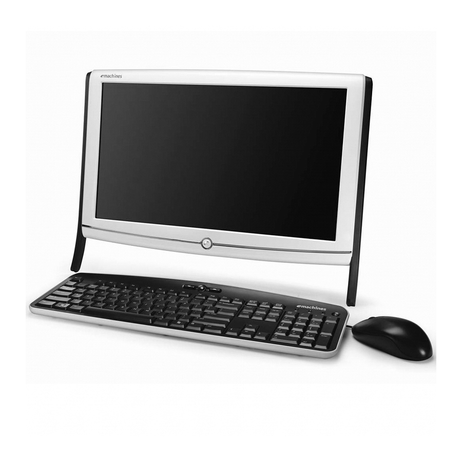
Your eMachines Computer tour This section describes port locations, indicators, and controls for the computer. IMPORTANT:Your computer’s hardware options, port locations, and indicators may vary from this illustration. Front View Component Power button Press this button to turn the power on or off. You can also configure the power button to operate in Standby/Resume mode or Hibernate mode. -
Page 14: Right View
Right View IMPORTANT:Your computer’s hardware options, port locations, and indicators may vary from this illustration. Component Optical disc drive Icon Use this drive to listen to audio CDs, install games and programs, watch DVDs, and store large files onto recordable discs (depending on drive type). -
Page 15: Left View
Left View IMPORTANT:Your computer’s hardware options, port locations, and indicators may vary from this illustration. Component Icon Brightness up Brightness down Memory card reader USB 2.0 port Headphone jack Microphone jack Rear View IMPORTANT:Your computer’s hardware options, port locations, and indicators may vary from this illustration. Chapter 1 Brightness Up/down... - Page 16 Kensington™ lock slot Component Icon Kensington™ lock slot Power connector Ethernet (network) jack USB ports PS/2 mouse port PS/2 keyboard port Audio line output jack Speakers Speakers Description Secure your computer to an object by connecting a Kensington cable lock to this slot. Plug the power cord into this connector.
-
Page 17: Using The Keyboard
Using the Keyboard The keyboard has several different types of keys and buttons. Feature Function keys Audio playback keys Windows key Fn key Application key Navigation keys Chapter 1 Icon Press these keys to start program actions. Each program uses different function keys for different purposes. -
Page 18: Windows Keys
Windows Keys The keyboard has two keys that perform Windows-specific functions. Windows key Pressed alone, this key has the same effect as clicking on the Windows Start button; it launches the Start menu. It can also be used with other keys to provide a variety of functions: <... -
Page 19: Hardware Specifications And Configurations
Crestline 945GSE(Atom platform) 998 ball uFCBGA 27x27mm ICH7-M (South Bridge) 82801GBM 652 BGA 31x31mm Cache Speed Tech Size 45 nm Controller Intel Atom N270 Processor • North Bridge (Navy-Pier 945GSE) • South Bridge (ICH7-M) • RTL8111DL 10/100/1000M Onboard HDA Codec ALC269 Specification Specification Package Acer P/N... - Page 20 Item Features PCI bus Interface • Supports PCI bus at 33MHz • PCI Rev.2.3 specification support. • Support for 64 bit addressing on PCI using DAC protocol. • SMBus: SM Bus Rev.2.0 compliant. • AC-Link for Audio and Telephony CODECs •...
- Page 21 Item Features • • • • • • • • • • • • • • • • • • • • • • • Wireless Module Item Model and Type Conformity Modulation Technique Frequency Range Channels Data Rate (Mbps) Security (WEP) Operating Operating...
- Page 22 Item Interface Internal transfer rate (Mbits/sec, max) I/O data transfer rate (Mbytes/sec max) DC Power Requirements Voltage Item Vendor & Model Name Capacity (MB) Bytes per sector Data heads Drive Format Disks Spindle speed (RPM) Performance Specifications Buffer size Interface Internal transfer rate (Mbits/sec, max) I/O data transfer rate...
- Page 23 Super-Multi Drive Item Vendor & model name HLDS GT20N Performance With CD Diskette Specification Transfer rate (MB/sec) Sustained: 3,600 KB/s (24x) max. Buffer Memory Interface Applicable disc formats DVD-ROM: • • • DVD-R: • • • • • DVD-RW: • •...
- Page 24 LCD 18.5" Item Vendor/model name Screen Diagonal (mm) Active Area (mm) Display resolution (pixels) Pixel Pitch Display Mode Typical White Luminance (cd/m Brightness Supported Colors Contrast Ratio Response Time (Optical Rise Time/Fall Time) msec Nominal Input Voltage VDD Interface Viewing Angle (degree) Horizontal: Vertical: Temperature Range (°C)
-
Page 25: System Utilities
System Utilities BIOS Setup Utility The BIOS Setup Utility is a hardware configuration program built into your computer’s BIOS (Basic Input/ Output System). Your computer is already properly configured and optimized, and you do not need to run this utility. However, if you encounter configuration problems, you may need to run Setup. -
Page 26: Information
Information The Information screen displays a summary of your computer hardware information. Info M a i n Advanced P r o c e s s o r T y p e P r o c e s s o r S p e e d S y s t e m M e m o r y : S y s t e m M a n u f a c t u r e r : P r o d u c t N a m e :... -
Page 27: Main
Main The Main screen allows the user to set the system time and date as well as enable and disable boot options. Info M a i n Advanced S y s t e m D a t e : S y s t e m T i m e : S y s t e m T i m e : S A T A P O R T 1 S A T A P O R T 1... -
Page 28: Advanced
Advanced The Advanced screen allows the user to configure the various advanced BIOS options. Info M a i n Advanced A d v a n c e d C h i p s e t F e a t u r e s I n t e g r a t e d P e r i p h e r a l s I n t e g r a t e d P e r i p h e r a l s H e l p... -
Page 29: Security
Security The Security screen contains parameters that help safeguard and protect your computer from unauthorized use. Info M a i n Advanced S u p e r v i s o r P a s s w o r d : S u p e r v i s o r P a s s w o r d : U s e r P a s s w o r d : U s e r P a s s w o r d :... -
Page 30: Removing A Password
Setting a Password Follow these steps as you set the user or the supervisor password: Use the ↑ and ↓ keys to highlight the Set Supervisor Password parameter and press the Enter key. The Set Supervisor Password box appears: E n t e r N e w P a s s w o r d C o n f i r m N e w P a s s w o r d Type a password in the “Enter New Password”... -
Page 31: Changing A Password
Changing a Password Use the ↑ and ↓ keys to highlight the Set Supervisor Password parameter and press the Enter key. The Set Password box appears. E n t e r C u r r e n t P a s s w o r d E n t e r N e w P a s s w o r d C o n f i r m N e w P a s s w o r d Type the current password in the Enter Current Password field and press Enter. -
Page 32: Power
Power The Power screen contains parameters used for device power management. Info M a i n Advanced A C P I S u s p e n d M o d e : A C P I S u s p e n d M o d e : P o w e r O n b y R T C A l a r m : P o w e r O n b y R T C A l a r m : P o w e r O n b y O n b o a r d L A N... -
Page 33: Pc Health
PC Health The PC Health screen displays CPU/Chipset temperature information and contains customizable safety monitors for the CPU. Info M a i n Advanced C P U T e m p e r a t u r e : C P U T e m p e r a t u r e : S y s t e m T e m p e r a t u r e : S y s t e m T e m p e r a t u r e : C P U C o r e... -
Page 34: Boot
Boot This menu allows the user to decide the order of boot devices to load the operating system. Bootable devices includes the USB diskette drives, the onboard hard disk drive and the DVD drive. Info M a i n Advanced B o o t p r i o r i t y o r d e r : B o o t p r i o r i t y o r d e r : 1 : I n t e r n a l H D D : H i t a c h i H T S 5 4 5 0 1 6 B 9 A 3 0 0 - ( S... -
Page 35: Exit
Exit The Exit screen allows you to save or discard any changes you made and quit the BIOS Utility. Info M a i n Advanced E x i t S a v i n g C h a n g e s E x i t S a v i n g C h a n g e s E x i t D i s c a r d i n g C h a n g e s E x i t D i s c a r d i n g C h a n g e s... -
Page 36: Bios Flash Utilities
BIOS Flash Utilities The BIOS flash memory update is required for the following conditions: • New versions of system programs • New features or options • Restore a BIOS when it becomes corrupted. This section contains instructions for the following BIOS utilities: •... -
Page 37: Dos Flash Utility
DOS Flash Utility Perform the following steps to use the DOS Flash Utility: Copy the flash utilities to the bootable diskette. Press F2 during boot to enter the Setup Menu. Select Boot Menu to modify the boot priority order, for example, if using USB HDD to Update BIOS, move USB HDD to position 1. -
Page 38: Winphlash Utility
WinPhlash Utility The Winflash utility consists of two files: • ZU1_3601.WPH (BIOS ROM file) • WinPhlash (BIOS windows flash tool) Perform the following steps to use the WinFlash Utility: Double click the WinPhlash executable to run the program. NOTE: You must run the program with administrator privileges for it to function properly. In the Specify New BIOS file field, enter the BIOS ROM file name and path. -
Page 39: Using Dmi Tools
Using DMI Tools Use QDMI30A to change the asset tag, product name, or serial number of the machine. Copy the file qdmi30a.exe to USB flash disk with bootable diskette or USB drive. Press F2 during boot to enter the Setup Menu. Select Boot Menu to modify the boot priority order, for example, if using a USB HDD to run DMI Tools, move USB HDD to position 1. - Page 40 To modify the serial number, key in “3” then key in a new string for the serial number as shown below. To modify the 1394 GUID number, key in “4” then key in a new string for the 1394 GUID number as shown below Chapter 2...
- Page 41 Chapter 2...
-
Page 42: Machine Disassembly And Replacement
Machine Disassembly and Replacement IMPORTANT:The outside housing and color may vary from the images that appear in this section. This chapter contains step-by-step procedures on how to disassemble the computer for maintenance and troubleshooting. Disassembly Requirements To disassemble the computer, you need the following tools: Wrist grounding strap and conductive mat for preventing electrostatic discharge •... -
Page 43: Disassembly Process
Disassembly Process Disassembly Flowchart Turn off power and disconnect all Remove cables before LCD Bezel proceeding Remove Remove Stand Assembly Switch Board Screw List Step Stand Assembly Remove Switch Board Support Legs LCD Module Inverter Board LCD Brackets ODD Module Remove Remove Support Legs... - Page 44 Step ODD Bracket ODD Board and Cable Speakers WLAN Antennas Power Board Cable HDD Module WLAN Board Mainboard Thermal Module Chapter 3 Screw M2*3 (Plated) M3.0*8.0 Self-tapping M2.0*4.0 Self-Tapping M2.0*4.0 (plated) M2.0*6.0 M3.0*8.0-Self-Tapping M3*3 M2.5*4 M3.0*5 M3.0*12.0-Self-Tapping M2.5*4 Quantity Part No.
-
Page 45: Removing The Stand Assembly
Removing the Stand Assembly 1. See “Pre-disassembly Instructions” on page 34. 2. Lift the stand assembly up as shown below. 3. Pry up the edges of the hinge cover using a plastic tool as shown below. 4. Push in and lift up on the top edge of the hinge cover until the securing tabs clear the slots. Chapter 3... - Page 46 5. Push in and lift up on the bottom edge of the hinge cover as shown until the securing tabs clear the slots. 6. Grasp the hinge cover with both hands to pull the top edge out and remove from the assembly. 7.
- Page 47 8. Remove the hinge from the back cover; pull down so the metal tabs on the hinge clear the slots in the back cover. Chapter 3...
-
Page 48: Removing The Lcd Bezel
Removing the LCD Bezel 1. See “Pre-disassembly Instructions” on page 34. 2. Using your fingers, pry the bezel away from the LCD screen starting from the top center. 3. Work your way from the center of the bezel to the right and left sides. 4. - Page 49 5. Lift the bezel away from the assembly as shown. IMPORTANT:The bezel is still attached to the assembly by a cable. Do not lift the bezel away completely 6. Unplug the switch board cable from the switch board. Chapter 3...
-
Page 50: Removing The Switch Board
Removing the Switch Board 1. See “Removing the LCD Bezel” on page 40. 2. Remove the two screws securing the Switch Board to the LCD Bezel. Step Switch Boards M2*6 (plated) 3. Lift the Switch Board away from the LCD Bezel. Chapter 3 Size Quantity... -
Page 51: Removing The Support Legs
Removing the Support Legs 1. See “Removing the LCD Bezel” on page 40 2. Remove the eight securing screws from the front of the computer as shown. Step Support legs M3.0*8 self-tapping 3. Remove the left leg from the assembly Size Quantity Screw Type... - Page 52 4. Remove the right leg from the assembly. Chapter 3...
-
Page 53: Removing The Lcd Module
Removing the LCD Module 1. See “Removing the Support Legs” on page 43 2. Remove the two securing screws from the LCD Module. Step LCD Module M3.0*8 self-tapping 3. Lift the module up high enough so that you are able to access the cables underneath. IMPORTANT:Do not lift the module completely away from the assembly: doing so may result in permanent damage to the cables and connectors. - Page 54 4. Unplug the inverter cable. 5. Unplug the LVDS cable. 6. Lift the LCD module away from the assembly and carefully place face-down on a clean lint-free cloth. Chapter 3...
-
Page 55: Removing The Inverter Board
Removing the Inverter Board 1. See “Removing the LCD Module” on page 45. 2. Unplug the Mainboard connector cable from the Inverter Board. 3. Unplug the lower connector to the LCD Panel. 4. Unplug the upper connector to the LCD Panel. Chapter 3... - Page 56 5. Unscrew the two securing screws holding the Inverter Board to the LCD Bracket. Step Size Quantity Screw Type Inverter Board M3.0*5 6. Lift the Inverter Board clear of the LCD assembly. Chapter 3...
-
Page 57: Removing The Lvds Cable And Lcd Brackets
Removing the LVDS cable and LCD Brackets 1. See “Removing the Inverter Board” on page 47. 2. Peel the LVDS cable away from the LCD module, taking care to grasp from the cloth adhesive strip 3. Peel the clear protective tape away from the connector and pull the connector out of the LCD module. Chapter 3... - Page 58 4. Un-screw the two screws securing the left LCD bracket to the LCD module and lift the bracket away from the module. Step LCD Bracket M3*5 5. Un-screw the two screws securing the right LCD bracket to the LCD module and lift the bracket away from the module.
-
Page 59: Removing The Odd Module
Removing the ODD Module 1. See “Removing the LCD Module” on page 45. 2. Remove the ESD spacer from the top of the drive. 3. Remove the single screw securing the ODD to the Back Cover. Step ODD Module M3.0*8.0 Self-Tapping Size Quantity Screw Type... - Page 60 4. Disconnect the ODD from the mainboard by pushing the ODD out of the lower cover. Remove the ODD from the lower cover 5. Insert an appropriate tool into the hole in the ODD bezel to eject the ODD tray 6.
- Page 61 7. Remove the two screws from the ODD bracket and pull the bracket away from the ODD module. Step Size Quantity Screw Type ODD Bracket M2*3 (Plated) Chapter 3...
-
Page 62: Removing The Odd Board And Cable
Removing the ODD Board and Cable 1. See “Removing the ODD Module” on page 51 2. Disconnect the ODD cable from the ODD Board. IMPORTANT:Do not remove the cable completely; the grounding cable is still attached to one of the screws. 3. -
Page 63: Removing The Speakers
Removing the Speakers 1. See “Removing the LCD Module” on page 45 2. Remove the four screws securing the speakers to the back cover. Step Speakers M2.0*4.0 Self-Tapping 3. Pull the speakers off the posts in the back panel. 4. Unplug the speaker cable from the mainboard. 5. -
Page 64: Removing The Wlan Antennas
Removing the WLAN Antennas 1. See “Removing the LCD Module” on page 45 2. Disconnect the antenna cables from the WLAN Board as shown. NOTE: Take note of the correct cable positioning: Grey to the Main connector and Black to the Aux connector. 3. - Page 65 4. Remove the adhesive tape securing the cables to the back cover. 5. Lift the antennas off of the mounting pins. 6. Remove the cables from the cable channels. Chapter 3...
-
Page 66: Removing The Rtc Battery
Removing the RTC Battery 1. See “Removing the LCD Module” on page 45. 2. Locate the RTC Battery. 3. Push the RTC battery in the direction indicated. The spring underneath will cause the RTC battery to pop up. 4. Lift the RTC Battery out of the Mainboard Chapter 3... -
Page 67: Removing The Power Board Cable
Removing the Power Board Cable 1. See “Removing the LCD Module” on page 45. 2. Disconnect the Power Board Cable from the Mainboard 3. Remove the single screw securing the grounding cable to the Back Cover Step Power Board M2.0*6.0 Cable Size Quantity... -
Page 68: Removing The Hdd Module
Removing the HDD Module 1. See “Removing the LCD Module” on page 45 2. Remove the single screw securing the HDD assembly to the Back Cover. Step HDD Module M3.0*8.0-Self-Tapping 3. Slide the HDD assembly in the direction indicated to separate the HDD from the SATA interface. Chapter 3 Size Quantity... - Page 69 4. Lift the HDD assembly out of the Back Cover. 5. Remove the four screws securing the HDD to the HDD Carriage. Step Size Quantity Screw Type HDD Module M3*3 6. Lift the HDD Carriage clear of the HDD Module. Chapter 3...
-
Page 70: Removing The Wlan Board
Removing the WLAN Board 1. See “Removing the LCD Module” on page 45 2. Disconnect the antenna cables from the WLAN Board as shown. NOTE: Take note of the correct cable positioning: Grey to the Main connector and Black to the Aux connector. 3. - Page 71 4. Remove the WLAN Board from the Mainboard Chapter 3...
-
Page 72: Removing The Mainboard
Removing the Mainboard 1. See “Removing the RTC Battery” on page 58. 2. See “Removing the WLAN Board” on page 62. 3. Disconnect the Speaker Cable from the Mainboard. 4. Disconnect the Power Board cable from the Mainboard. 5. Disconnect the ODD Cable from the Mainboard. Chapter 3... - Page 73 6. Remove the two screws securing the thermal module to the back cover. Step Mainboard M3.0*12-Self Tapping 7. Remove the screw securing the ODD grounding cable to the mainboard and back cover Step Mainboard M3.0*5 Size Quantity Size Quantity Screw Type Screw Type Chapter 3...
- Page 74 8. Remove the remaining five screws securing the mainboard to the back cover. Step Size Quantity Screw Type Mainboard M3.0*5 9. Using both hands, Tilt the Mainboard up and pull clear of the Back Cover as shown. Chapter 3...
-
Page 75: Removing The Thermal Module
Removing the Thermal Module 1. See “Removing the Mainboard” on page 64 2. Place the Mainboard on a clean surface. 3. Remove the four screws securing the Thermal Module to the Mainboard. Step Thermal Module M2.5*4 4. Using both hands, gently twist the Thermal Module left and right to break the thermal paste seal between the Thermal Module and CPU. -
Page 76: Removing The Memory Module
Removing the Memory Module 1. See “Removing the ODD Module” on page 51 2. Push out the release latches on both sides of the DIMM socket to release the DIMM Module. 3. Remove the DIMM Module from the Mainboard. Chapter 3... -
Page 77: Reassembly Procedure
Reassembly Procedure Replacing the Memory Modules 1. Remove the DIMM Module from the Mainboard. 2. Push down on both sides of the DIMM module to lock it into place. Replacing the Thermal Module IMPORTANT: Ensure all heat pads are in place before replacing the Thermal Module. The following thermal pads are approved for use: Eapus XR-PE •... - Page 78 2. Place the Thermal Module onto the Mainboard, taking care to align the screw holes before allowing the thermal pad to contact the CPU. 3. Replace the four securing screws. Step Size Quantity Screw Type Thermal Module M2.5*4 Chapter 3...
-
Page 79: Replacing The Mainboard
Replacing the Mainboard 1. Using both hands, insert the left edge of the mainboard into the Back Cover and lower into place, aligning the mainboard with the screw holes. 2. Replace the five screws in the positions indicated below to secure the mainboard to the back cover. Step Mainboard M3.0*5... - Page 80 3. Replace the screw to secure the ODD grounding cable to the mainboard and back cover. Step Mainboard M3.0*5 4. Replace the two screws to secure the thermal module to the back cover. Step Mainboard M3.0*12-Self Tapping Chapter 3 Size Quantity Size Quantity...
- Page 81 5. Connect the ODD Cable to the Mainboard. 6. Connect the Power Board cable to the Mainboard. 7. Connect the Speaker Cable to the Mainboard. Chapter 3...
-
Page 82: Replacing The Wlan Board
Replacing the WLAN Board 1. Insert the WLAN Board in to the Mainboard connector in the direction of the arrow. 2. Replace the single securing screw. Step WLAN Board M2.5*4 Chapter 3 Size Quantity Screw Type... -
Page 83: Replacing The Hdd Modules
3. Connect the antenna cables to the WLAN Board terminals as shown. NOTE: Take note of the correct cable positioning: Black to the red callout and gray to the blue callout. Replacing the HDD Modules 1. Place HDD Carriage onto the HDD Module, taking care to align the screw holes. Chapter 3... - Page 84 2. Replace the four securing screws. Step Size Quantity Screw Type HDD Module M3*3 3. Place the HDD assembly into the Back Cover between the HDD guides. 4. Slide the HDD assembly in the direction indicated to connect the HDD to the SATA interface. Chapter 3...
-
Page 85: Replacing The Power Board Cable
5. Replace the single screw to secure the HDD assembly to the Back Cover. Step HDD Module M3.0*8.0-Self-Tapping Replacing the Power Board Cable 1. Insert the single screw securing the grounding cable to the Back Cover. Step Power Board M2.0*6.0 Cable Size Quantity... -
Page 86: Replacing The Rtc Battery
2. Connect the Power Board Cable to the Mainboard. Replacing the RTC Battery 1. Push the RTC battery in the direction indicated until the battery clicks into place. Replacing the WLAN Antennas 1. Insert the cables into the cable channels. Chapter 3... - Page 87 2. Place the antennas onto the mounting pins. 3. Replace the adhesive tape securing the cables to the back cover. 4. Insert the two screws securing the WLAN Antennas to the Back Cover. Step Size Quantity Screw Type WLAN Antennas M2.0*4.0 (plated) Chapter 3...
-
Page 88: Replacing The Speakers
5. Connect the antenna cables to the WLAN Board as shown. NOTE: Take note of the correct cable positioning: Grey to the Main connector and Black to the Aux connector. Replacing the Speakers 1. Plug the speaker cable into the mainboard. 2. - Page 89 3. Insert the speaker cable into the cable clips. 4. Insert the four screws to secure the speakers to the back cover. Step Size Quantity Screw Type Speakers M2.0*4.0 Self-Tapping Chapter 3...
-
Page 90: Replacing The Odd Board And Cable
Replacing the ODD Board and Cable 1. Place the ODD board onto the mounting pins on the back cover and insert the two securing screws as shown. IMPORTANT:Be sure the grounding cable is attached to one of the screws as indicated. Step ODD Board M3.0*8.0 Self-tapping... -
Page 91: Replacing The Odd
Replacing the ODD 1. Insert the two screws to secure the ODD bracket to the ODD module. Step ODD Bracket M2*3 (Plated) 2. Insert the ODD bezel into the front of the ODD module. Size Quantity Screw Type Chapter 3... - Page 92 3. Insert the ODD into the lower cover and connect the ODD to the mainboard by pushing the ODD into the SATA interface on the ODD board. 4. Replace the single screw to secure the ODD to the Back Cover. Step Size Quantity...
-
Page 93: Replacing The Lcd Brackets And Cable
Replacing the LCD Brackets and Cable 1. Place the right bracket onto the LCD module and insert the two screws to secure it in place. Step LCD Bracket M3*5 2. Place the left bracket onto the LCD module and insert the two screws to secure it in place. IMPORTANT:be sure to thread the LCD backlight cables through the bracket as shown. -
Page 94: Replacing The Inverter Board
3. Insert the LVDS cable connector into the LCD module and apply the clear protective tape to secure the connector in place. 4. Adhere the LVDS Cable to the back of the LCD panel. Replacing the Inverter Board 1. Place the Inverter Board onto the LCD assembly, taking care to mount it to the pins on the LCD bracket. Chapter 3... - Page 95 2. Insert the two screws to secure the Inverter Board to the LCD Bracket. Step Size Quantity Screw Type LCD Bezel M3.0*5 3. Plug the upper connector into the LCD Panel. 4. Plug the lower connector into the LCD Panel. Chapter 3...
-
Page 96: Replacing The Lcd Module
5. Plug the Mainboard connector cable into the Inverter Board. Replacing the LCD Module 1. Hold the LCD module above the main assembly as shown. 2. Plug in the LVDS cable. Chapter 3... - Page 97 3. Plug in the inverter cable. 4. Place the module down onto the assembly, taking care to align the brackets with the screw holes in the back cover 5. Insert the two securing screws into the LCD Module. Step Size Quantity Screw Type LCD Module...
-
Page 98: Replacing The Support Legs
Replacing the Support Legs 1. Insert the right and left support legs onto the assembly as shown. The legs’ center tabs should cover the LCD module bracket tabs, and the bottom tabs should be covered by the LCD bracket tabs. 2. -
Page 99: Replacing The Switch Board
Replacing the Switch Board 3. Place the Switch Board onto the LCD Bezel. 4. Insert the two screws to secure the Switch Board to the LCD Bezel. Step Switch Boards M2*6 (plated) Size Quantity Screw Type Chapter 3... -
Page 100: Replacing The Lcd Bezel
Replacing the LCD Bezel 1. Plug the switch board cable into the switch board. 2. Place the bezel onto assembly as shown. 3. Starting at the bottom edge, press the bezel into the back cover so that the securing tabs along the outside edges snap into place. -
Page 101: Replacing The Stand Assembly
Replacing the Stand Assembly 1. Attach the hinge to the back cover; pull down so the metal tabs on the hinge clear the slots in the back cover. 2. Replace the three screws securing the hinge to the back cover. Step Switch Boards M4*8... - Page 102 4. Push in and down to allow the securing tabs to clear the back cover and press down. an audible click indicates that the hinge cover is in place 5. Raise the stand slightly and check that the bottom edge of the hinge cover is fully inserted. If not, push it into place, pushing in as indicated with your fingers, and down on the top of the hinge cover with your thumbs.
- Page 103 Chapter 3...
-
Page 104: Troubleshooting
Common Problems Use the following procedure as a guide for computer problems. NOTE: The diagnostic tests are intended to test only Acer products. Non-Acer products, prototype cards, or modified options can give false errors and invalid system responses. Obtain the failing symptoms in as much detail as possible. -
Page 105: Component Failure
Component Failure If a component fails, follow the flowchart below to isolate the problem Memory Module Wireless LAN Failure component on Component pass Component fail Replace module Replace according to Mainboard procedure ODD Failure If the ODD exhibits any of the following symptoms it may be faulty: Audio CDs do not play when loaded •... - Page 106 Double-click lDE ATA/ATAPI controllers. If a device displays a down arrow, right-click on the device and click Enable. Double-click DVD/CD-ROM drives. If the device displays a down arrow, right-click on the device and click Enable. Check that there are no yellow exclamation marks against the items in lDE ATA/ATAPI controllers. If a device has an exclamation mark, right-click on the device and uninstall and reinstall the driver.
-
Page 107: Sound Problems
Double-click IDE ATA/ATAPI controllers, then right-click ATA Device 0. Click Properties and select the Advanced Settings tab. Ensure that the Enable DMA box is checked and click OK. Repeat for the other ATA Devices shown if applicable. Drive Not Detected If Windows cannot detect the drive, perform the following actions one at a time to correct the problem. - Page 108 • No hardware is listed under Other Devices. Roll back the audio driver to the previous version, if updated recently. Remove and reinstall the audio driver. Ensure that all volume controls are set mid range: Click the volume icon on the taskbar and drag the slider to 50. Ensure that the volume is not muted. Click Mixer to verify that other audio applications are set to 50 and not muted.
-
Page 109: Wireless Failure
Wireless Failure If the wireless functionality fails, use the following flowchart to determine the required action: Speaker Failure If sound problems are experienced, perform the following actions one at a time to correct the problem. Reboot the computer. Navigate to Start Control Panel the Device Manager to determine that: The device is properly installed. - Page 110 Restore system and file settings from a known good date using System Restore. If the issue is not fixed, repeat the preceding steps and select an earlier time and date. 10. Reinstall the Operating System. 11. If the Issue is still not resolved, see “Online Support Information” on page 142. Chapter 4...
-
Page 111: Lcd Failure
LCD Failure If the integrated LCD display fails, use the following flowchart to determine the required action: Is the LVDS cable properly connected? Test the LVDS Cable Is the inverter properly Test the inverter cables Test the LCD Module Change Mainboard No POST or Video If the POST or video doesn’t display, perform the following actions one at a time to correct the problem. - Page 112 If the computer boots correctly, add the devices one by one until the failure point is discovered. Reseat the memory modules. Remove the drives (see “Disassembly Process” on page 35). If the Issue is still not resolved, see “Online Support Information” on page 142. Abnormal Video Display If video displays abnormally, perform the following actions one at a time to correct the problem.
-
Page 113: General Troubleshooting Issues
General Troubleshooting Issues Computer Shutsdown Intermittently If the system powers off at intervals, perform the following actions one at a time to correct the problem. Check the power cable is properly connected to the computer and the electrical outlet. Remove any extension cables between the computer and the outlet. Remove any surge protectors between the computer and the electrical outlet. -
Page 114: Hdd Not Operating Correctly
HDD Not Operating Correctly If the HDD does not operate correctly, perform the following actions one at a time to correct the problem. Disconnect all external devices. Run a complete virus scan using up-to-date software to ensure the computer is virus free. Run the Windows Vista Startup Repair Utility: insert the Windows Vista Operating System DVD in the ODD and restart the computer. - Page 115 11. Remove and reinstall the mouse driver. 12. Check the Device Manager to determine that: The device is properly installed. There are no red Xs or yellow exclamation marks. • There are no device conflicts. • No hardware is listed under Other Devices. •...
-
Page 116: Intermittent Problems
NOTE: Verify that the power supply being used at the time of the failure is operating correctly. Power-off the computer. Visually check for damage. If any problems are found, replace the FRU. Remove or disconnect all of the following devices: Non-Acer devices • Printer, mouse, and other external devices •... -
Page 117: Jumper And Connector Locations
Jumper and Connector Locations Top View SODIMM connector 2 USB connector RJ45 connector Item Description HDD / SSD SATA 2 connector DDR2 DDR2 SODIMM sockets Media Media card reader Card connector USB connectors PS2 Connector for Mouse Mouse Chapter 5 Media Card Reader connector... -
Page 118: Bottom View
Bottom View ODD Cable connector Inverter connector connector Item ODD cable connector Cable Speaker Internal speaker connector Inverter Connector for inverter RTC Battery connector Battery Description Item WLAN Switch Cable Switch Cable Speaker connector connector Battery WLAN Card connector Description Wireless LAN card slot Connector for LVDS cable Power Board cable connector... -
Page 119: Clearing Password Check And Bios Recovery
Clearing Password Check and BIOS Recovery This section provide you the standard operating procedures of clearing password and BIOS recovery for eMachines EZ1600/EZ1601 Series. The eMachines EZ1600/EZ1601 Series provides one Hardware Open Gap on the main board for clearing password check. Clearing Password Check Hardware Open Gap Description Item... -
Page 120: Bios Recovery By Crisis Disk
BIOS Recovery by Crisis Disk BIOS Recovery Boot Block: BIOS Recovery Boot Block is a special block of BIOS. It is used to boot up the system with minimum BIOS initialization. Users can enable this feature to restore the BIOS firmware to a successful one once the previous BIOS flashing process failed. - Page 121 A confirmation screen displays. Click the OK button on the left to continue. Click the (N) button when prompted to complete the process. Insert the Crisis Disk in to the USB floppy drive attached to the BIOS flash failed system. Chapter 5...
- Page 122 In the power-off state, unplug the AC power and hold Fn+Esc then plug the AC power in. 10. Press the Power button. The system powers on and the Crisis BIOS Recovery process begins. BIOS Boot Block begins restoring the BIOS code from the Crisis floppy disk to BIOS ROM on the failed systems.
-
Page 123: Fru (Field Replaceable Unit) List
Heat Sink Hard Disk Drive Hard Disk Drive Bracket ODD Bezel Front Bezel Assembly LCD Panel Left LCD Bracket Power Switch Board Mainboard Inverter Board Left Support Leg Optical Disk Drive Interface Board Chapter 6 Description Chapter 6 Acer P/N... - Page 124 Right Support Leg Rear Cover Sub Assembly Optical Disk Drive Description Acer P/N Chapter 6...
-
Page 125: Emachines Ez1600/Ez1601 Fru List
eMachines EZ1600/1601 FRU List Category Adapter Antenna Board Cable Chapter 6 Part No. AP.06501.030 ADP 19V 3.42A(ADP-65JH DBK 100-240V) ANTENNA C680-520185-A WLAN INV(SMD)(17~22V,VO=1700V) TWS-449-349 MB.NAS06.001 EL7 MB (945GSE) CPU 1.6G PCB EL7 ODD/B(2L,37*17,REVB) PCB EL7 SW/B(2L,55*15,REVD) NI.10200.012 WLAN 802.11 B/G(9WEM106QCF00Q) CE NI.10200.024 WLAN 802.11 B/G(9WEM106QCF00Q) US CABLE ASSY EL7 INVER(299MM,10P,30V,1A) - Page 126 Category Case/Cover/Bracket Assembly Fan/Heat Sink Part No. CABLE ASSY EL7 SW(215MM,10P,30V,1A) PWR CORD VA02S31161218505 US-110V,3P HS.NAS00.001 EL7 REAR COVER SUB ASSY HS.NAS00.002 EL7 REAR COVER SUB ASSY(BLACK) PZ.NAS00.001 EL7 FRONT BEZEL SUB ASSY PZ.NAT00.001 EL7 FRONT BEZEL SUB ASSY(BLACK) BRACKET HDD EL7(FBEL7005,REV3A) Kick Stand Kick Stand Black BRACKET LCD L EL7(FBEL7003,REV3A)
- Page 127 Category Hard Drive Keyboard Memory Modem Chapter 6 Part No. HEAT SINK ASV EL7(FBEL7001,REV3A) KF.16G0B.002 Flash Disk SANDISK SSD NAND 16GB SDSA3AD- 016G LF KH.16007.024 HDD HGST 2.5" 5400rpm 160GB HTS545016B9A300 Panther B SATA LF F/W:C60F KH.25007.015 HDD HGST 2.5" 5400rpm 250GB HTS545025B9A300 Panther B SATA LF F/W:C60F KH.16001.034 HDD SEAGATE 2.5"...
-
Page 128: Screw List
Category Mouse Speaker Sponge Screw List Part Number SCREW M2.5*4.0-I(NI)(NYLOK)IRON SCREW2.5*3I(HEAD4.5*0.5)(BNI)(NYLOK)IRON SCREW M2.0*5.0-I(NI)(NYLOK)IRON SCREW M2.0*5.0 I-(BNI)(NYLOK) IRON SCREW M3.0*4.0-I(NI)(NYLOK) IRON SCREW T2.0*4.0-I(NI)IRON SCREW T2.0*6.0-I(BZN)IRON SCREW M4.0*8.0-F(MC) (NYLOK)IRON SCREW T3.0*12-B(BZN) IRON SCREW M2.0*4.0-NI(NYLOK)IRON SCREW T3.0*5.0-B(NI)IRON SCREW T3*8-B(BNI) SCREW M2.0*2.5-I(NI)(NYLOK) IRON Part No. FX.10100.023 Pro-Nets VD56UL External USB Without any brand logo Rev 1.0... - Page 129 Chapter 6...
-
Page 130: Model Definition And Configuration
Model Definition and Configuration Model Acer Part no Name PW.NAS05.015 EZ1600 PW.NAS05.014 EZ1600 PW.NAS05.013 EZ1600 PW.NAS05.012 EZ1600 PW.NAS05.011 EZ1600 PW.NAS05.010 EZ1600 PW.NAS0C.004 EZ1600 PW.NAS05.009 EZ1600 PW.NAS05.008 EZ1600 PW.NAS05.007 EZ1600 PW.NAS05.006 EZ1600 PW.NAS05.005 EZ1600 PW.NAS0C.002 EZ1600 PW.NAS0C.003 EZ1600 PW.NAS05.002 EZ1600 PW.NAS0C.001 EZ1600 PW.NAS05.004... - Page 131 Model Acer Part no Name PW.NAT05.004 EZ1601 PW.NAT0C.002 EZ1601 PW.NAT05.003 EZ1601 PW.NAT0C.005 EZ1601 PW.NAT0C.006 EZ1601 PW.NAT0C.001 EZ1601 PW.NAT05.010 EZ1601 PW.NAT05.009 EZ1601 PW.NAT05.001 EZ1601 PW.NAT05.007 EZ1601 PW.NAT05.008 EZ1601 PW.NAT05.013 EZ1601 PW.NAT05.011 EZ1601 PW.NAT05.012 EZ1601 PW.NAT05.014 EZ1601 PW.NAT05.015 EZ1601 S1.NAT05.002 EZ1601 S1.NAT05.001 EZ1601 S1.VA606.001...
- Page 132 Acer Part no PW.NAS0C.002 EZ1600 AAP002 LinuxXWTHE02/ATMN270B/SO1GBII6*1/N250GB5.4KS*1/NSM8XS/D18.5W/ 802.11bgn/PS2/eCooper2/PS2Opt/PB PW.NAS0C.003 EZ1600 AAP002 LinuxXWTHE02/ATMN270B/SO2GBII6*1/N250GB5.4KS*1/NSM8XS/D18.5W/ 802.11bgn/PS2/eCooper2/PS2Opt/PB PW.NAS05.002 EZ1600 EMEA002 XPHR17e/ATMN270B/SO1GBII6*1/N160GB5.4KS*1/NSM8XS/D18.5W/ mCard/PS2/eCooper2/PS2Opt/PB PW.NAS0C.001 EZ1600 EMEA002 LinuxXWFIe01/ATMN270B/SO1GBII6*1/N160GB5.4KS*1/NSM8XS/D18.5W/ mCard/PS2/eCooper2/PS2Opt/PB PW.NAS05.004 EZ1600 AAP002 XPHSGE02/ATMN270B/SO1GBII6*1/N160GB5.4KS*1/NSM8XS/D18.5W/ 802.11bgn/PS2/eCooper2/PS2Opt/PB PW.NAS05.001 EZ1600 TWN002 XPHTWE2/ATMN270B/SO1GBII6*1/N160GB5.4KS*1/NSM8XS/D18.5W/ 802.11bgn/PS2/eCooper2/PS2Opt/PB PW.NAS05.003 EZ1600 AAP002 XPHJPE1/ATMN270B/SO1GBII6*1/N160GB5.4KS*1/NSM8XS/D18.5W/ 802.11bgn/PS2/eCooper2/PS2Opt/PB S1.NAS05.003 EZ1600 Sample EMEA002 XPHZAe1/ATMN270B/SO2GBII6*1/N160GB5.4KS*1/NSM8XS/ D18.5W/PS2/eCooper2/PS2/eCooper...
- Page 133 Acer Part no PW.NAT05.003 EZ1601 EMEA002 XPHR17e/ATMN270B/SO1GBII6*1/N160GB5.4KS*1/NSM8XS/D18.5W/ mCard/PS2/eCooper/PS2Opt/PB PW.NAT0C.005 EZ1601 AAP002 LinuxXWTHE02/ATMN270B/SO1GBII6*1/N250GB5.4KS*1/NSM8XS/D18.5W/ 802.11bgn/PS2/eCooper/PS2Opt/PB PW.NAT0C.006 EZ1601 AAP002 LinuxXWTHE02/ATMN270B/SO2GBII6*1/N250GB5.4KS*1/NSM8XS/D18.5W/ 802.11bgn/PS2/eCooper/PS2Opt/PB PW.NAT0C.001 EZ1601 EMEA002 LinuxXWFIe01/ATMN270B/SO1GBII6*1/N160GB5.4KS*1/NSM8XS/D18.5W/ mCard/PS2/eCooper/PS2Opt/PB PW.NAT05.010 EZ1601 AAP002 XPHVNE03/ATMN270B/SO1GBII6*1/N160GB5.4KS*1/NSM8XS/D18.5W/ 802.11bgn/PS2/eCooper/PS2Opt/PB PW.NAT05.009 EZ1601 AAP002 XPHTHE02/ATMN270B/SO1GBII6*1/N160GB5.4KS*1/NSM8XS/D18.5W/ 802.11bgn/PS2/eCooper/PS2Opt/PB PW.NAT05.001 EZ1601 TWN002 XPHTWE2/ATMN270B/SO1GBII6*1/N160GB5.4KS*1/NSM8XS/D18.5W/ 802.11bgn/PS2/eCooper/PS2Opt/PB PW.NAT05.007 EZ1601 AAP002 XPHJPE1/ATMN270B/SO1GBII6*1/N160GB5.4KS*1/NSM8XS/D18.5W/ 802.11bgn/PS2/eCooper/PS2Opt/PB...
- Page 134 Acer Part no Chassis PW.NAS05.002 eClapton AIO 18.5 White PW.NAS0C.001 eClapton AIO 18.5 White PW.NAS05.004 eClapton AIO 18.5 White PW.NAS05.001 eClapton AIO 18.5 White PW.NAS05.003 eClapton AIO 18.5 White S1.NAS05.003 eClapton AIO 18.5 White S1.NAS05.002 eClapton AIO 18.5 White S1.NAS05.001 eClapton AIO 18.5 White...
- Page 135 Acer Part no Memory 1 PW.NAS05.013 SO1GBII6 PW.NAS05.012 SO1GBII6 PW.NAS05.011 SO1GBII6 PW.NAS05.010 SO1GBII6 PW.NAS0C.004 SO1GBII6 PW.NAS05.009 SO1GBII6 PW.NAS05.008 SO1GBII6 PW.NAS05.007 SO1GBII6 PW.NAS05.006 SO1GBII6 PW.NAS05.005 SO1GBII6 PW.NAS0C.002 SO1GBII6 PW.NAS0C.003 SO2GBII6 PW.NAS05.002 SO1GBII6 PW.NAS0C.001 SO1GBII6 PW.NAS05.004 SO1GBII6 PW.NAS05.001 SO1GBII6 PW.NAS05.003 SO1GBII6 S1.NAS05.003 SO2GBII6 S1.NAS05.002...
- Page 136 Acer Part no Memory 1 PW.NAT0C.006 SO2GBII6 PW.NAT0C.001 SO1GBII6 PW.NAT05.010 SO1GBII6 PW.NAT05.009 SO1GBII6 PW.NAT05.001 SO1GBII6 PW.NAT05.007 SO1GBII6 PW.NAT05.008 SO1GBII6 PW.NAT05.013 SO1GBII6 PW.NAT05.011 SO1GBII6 PW.NAT05.012 SO1GBII6 PW.NAT05.014 SO1GBII6 PW.NAT05.015 SO1GBII6 S1.NAT05.002 SO1GBII6 S1.NAT05.001 SO1GBII6 S1.VA606.001 SO1GBII6 S1.VA706.001 SO1GBII6 Acer Part no Keyboard PW.NAS05.015...
- Page 137 Acer Part no Keyboard PW.NAS05.003 PS2/eCooper2 S1.NAS05.003 PS2/eCooper2 S1.NAS05.002 PS2/eCooper2 S1.NAS05.001 PS2/eCooper2 PW.NAT05.025 PS2/eCooper PW.NAT05.024 PS2/eCooper PW.NAT05.023 PS2/eCooper PW.NAT05.022 PS2/eCooper PW.NAT05.021 PS2/eCooper PW.NAT05.020 PS2/eCooper PW.NAT05.019 PS2/eCooper PW.NAT05.018 PS2/eCooper PW.NAT05.002 PS2/eCooper PW.NAT05.017 PS2/eCooper PW.NAT05.016 PS2/eCooper PW.NAT05.006 PS2/eCooper PW.NAT0C.004 PS2/eCooper PW.NAT05.005 PS2/eCooper PW.NAT0C.003...
- Page 138 Acer Part no Keyboard PW.NAT05.014 PS2/eCooper PW.NAT05.015 PS2/eCooper S1.NAT05.002 PS2/eCooper2 S1.NAT05.001 PS2/eCooper2 S1.VA606.001 PS2/0810 S1.VA706.001 PS2/0810 Appendix A Mouse Country Kit PS2Opt/PB INE02 PS2Opt/PB SGE02 PS2/ ZAe1 eCooper PS2/ ZAe1 eCooper PS2Opt/PB PS2Opt/PB Softload Country Kit XPHINE02 XPHSGE02 XPHZAe1 XPHZAe1...
- Page 139 Appendix A...
-
Page 140: Test Compatible Components
Appendix B Test Compatible Components This computer’s compatibility is tested and verified by Acer’s internal testing department. All of its system ® ® functions are tested under Windows XP Home, Windows XP Pro environment. Refer to the following lists for components, adapter cards, and peripherals which have passed these tests. -
Page 141: Microsoft® Windows® Vista Environment Test
Microsoft Windows ® BRAND Adapter DELTA Add on card Foxconn 802.11 b/g/n (mini-card) Quanta 802.11 b/g (mini-card) Bezel 18.5 AIO eClapton White 18.5 AIO eClapton Black 18.5 AIO vClapton Black Card Reader AIO 4-in-1 CR eClapton Chassis eMachines eClapton AIO 18.5 Black eMachines eClapton AIO 18.5 White... - Page 142 BRAND Keyboard CHICONY PS2/eCooper CHICONY PS2/eCooper2 CHICONY PS2/eCooper CHICONY PS2/eCooper2 CHICONY PS2/eCooper CHICONY PS2/eCooper2 CHICONY PS2/eCooper CHICONY PS2/eCooper2 CHICONY PS2/eCooper CHICONY PS2/eCooper2 CHICONY PS2/eCooper CHICONY PS2/eCooper2 CHICONY PS2/eCooper CHICONY PS2/eCooper2 CHICONY PS2/eCooper CHICONY PS2/eCooper2 CHICONY PS2/eCooper CHICONY PS2/eCooper CHICONY PS2/eCooper2 CHICONY PS2/eCooper2 CHICONY...
- Page 143 BRAND CHICONY PS2/eCooper2 CHICONY PS2/eCooper CHICONY PS2/eCooper2 CHICONY PS2/eCooper CHICONY PS2/eCooper2 CHICONY PS2/eCooper CHICONY PS2/eCooper2 CHICONY PS2/eCooper CHICONY PS2/eCooper2 CHICONY PS2/eCooper CHICONY PS2/eCooper2 CHICONY PS2/eCooper CHICONY PS2/eCooper2 CHICONY PS2/eCooper CHICONY PS2/eCooper2 CHICONY PS2/eCooper CHICONY PS2/eCooper2 CHICONY PS2/eCooper CHICONY PS2/eCooper2 CHICONY PS2/eCooper CHICONY PS2/eCooper2...
- Page 144 BRAND CHICONY PS2/eCooper2 CHICONY PS2/eCooper CHICONY PS2/eCooper2 CHICONY PS2/eCooper CHICONY PS2/eCooper2 CHICONY PS2/eCooper CHICONY PS2/eCooper2 CHICONY PS2/eCooper CHICONY PS2/eCooper CHICONY PS2/eCooper2 CHICONY PS2/eCooper2 CHICONY PS2/eCooper CHICONY PS2/eCooper2 CHICONY PS2/eCooper CHICONY PS2/eCooper2 CHICONY PS2/eCooper2 CHICONY PS2/eCooper CHICONY PS2/eCooper2 CHICONY PS2/eCooper CHICONY PS2/eCooper2 PRIMAX PS2/eCooper...
- Page 145 BRAND PRIMAX PS2/eCooper PRIMAX PS2/eCooper2 PRIMAX PS2/eCooper PRIMAX PS2/eCooper2 PRIMAX PS2/eCooper PRIMAX PS2/eCooper2 PRIMAX PS2/eCooper PRIMAX PS2/eCooper2 PRIMAX PS2/eCooper PRIMAX PS2/eCooper2 PRIMAX PS2/eCooper PRIMAX PS2/eCooper2 PRIMAX PS2/eCooper PRIMAX PS2/eCooper PRIMAX PS2/eCooper2 PRIMAX PS2/eCooper2 PRIMAX PS2/eCooper PRIMAX PS2/eCooper2 PRIMAX PS2/eCooper PRIMAX PS2/eCooper2 PRIMAX PS2/eCooper...
- Page 146 BRAND PRIMAX PS2/eCooper2 PRIMAX PS2/eCooper PRIMAX PS2/eCooper2 PRIMAX PS2/eCooper PRIMAX PS2/eCooper2 PRIMAX PS2/eCooper PRIMAX PS2/eCooper2 PRIMAX PS2/eCooper PRIMAX PS2/eCooper2 PRIMAX PS2/eCooper PRIMAX PS2/eCooper2 PRIMAX PS2/eCooper PRIMAX PS2/eCooper2 PRIMAX PS2/eCooper PRIMAX PS2/eCooper2 PRIMAX PS2/eCooper PRIMAX PS2/eCooper2 PRIMAX PS2/eCooper PRIMAX PS2/eCooper2 PRIMAX PS2/eCooper PRIMAX PS2/eCooper2...
- Page 147 BRAND PRIMAX PS2/eCooper PRIMAX PS2/eCooper PRIMAX PS2/eCooper2 PRIMAX PS2/eCooper2 PRIMAX PS2/eCooper PRIMAX PS2/eCooper2 PRIMAX PS2/eCooper PRIMAX PS2/eCooper2 PRIMAX PS2/eCooper PRIMAX PS2/eCooper2 PRIMAX PS2/eCooper PRIMAX PS2/eCooper2 PRIMAX PS2/eCooper PRIMAX PS2/eCooper2 D18.5WXGA D18.5WXGA D18.5WXGA D18.5WXGA SAMSUNG D18.5WXGA SAMSUNG D18.5WXGA Mainboard Type Keyboard PRIMAX KB-0511 PS/2 Standard 105KS Black Spanish Keyboard PRIMAX KB-0511 PS/2 Standard 105KS Black Spanish Latin...
- Page 148 BRAND eClapton Q945GSE_1394(N)_Lo go(N) Memory MICRON SO1GBII6 NANYA SO1GBII6 NANYA SO2GBII6 SAMSUNG SO1GBII6 SAMSUNG SO2GBII6 Modem Pro-Nets 56K MDM USB Mouse PS2/eCooper eMachines PS2/eCooper Logitech USB/0810 Logitech PS2Opt/PB HLDS NSM8XS Appendix B Type MB Kit Q945GSE Intel 945GSE ICH7M RTL8111DL AIO 18.5 no W/O 1394 LF Memory MICRON SO-DIMM DDRII 667 1GB MT8HTF12864HDY-667G1 LF 64*16 0.065um...
- Page 149 Appendix B...
-
Page 150: Online Support Information
This section describes online technical support services available to help you repair your Acer Systems. If you are a distributor, dealer, ASP or TPM, please refer your technical queries to your local Acer branch office. Acer Branch Offices and Regional Business Units may access our website. However some information sources will require a user i.d. -
Page 151: Index
BIOS vendor 12 Version 12 – , ??– BIOS Utility Advanced 20 Boot 26 Exit 27 Information 18 Main 19 Navigating 17 PC Health 25 Power 24 Save and Exit 27 Security 21 System Security 27 Board Layout Bottom View 110 Top View 109 Disassembly General Information 34... - Page 152 – , ??– BIOS 17 Windows 2000 Environment Test WLAN Board Removing 62 Replacing 74...
Need help?
Do you have a question about the EZ1601-01 and is the answer not in the manual?
Questions and answers