
Related Manuals for Flomag 3000

Summary of Contents for Flomag 3000
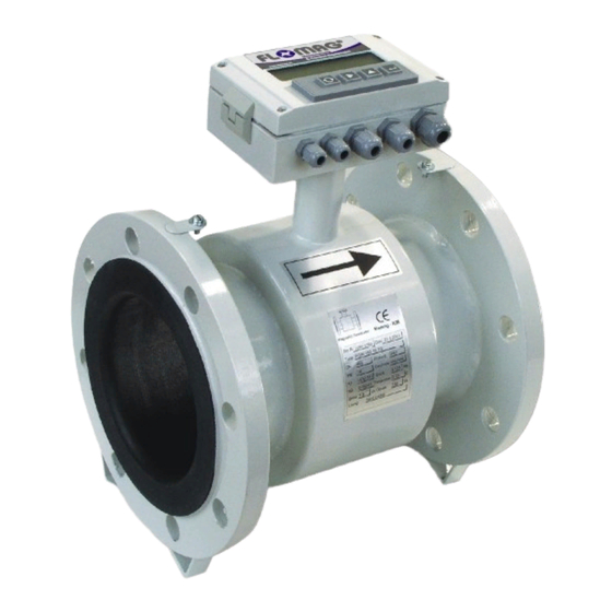
- Page 1 Magnetic Flowmeter FLOMAG 3000 ® FLOMAG s.r.o. Šumavská 5 CZ-602 00 Brno Czech Republic tel: +420 541212539 fax: +420 549240356 e-mail: info@flomag.com Installation and Operation www.flomag.com...
-
Page 3: Principle Of Measurement
Principle of measurement An magnetic flowmeter is used for volume flow measurement of electrically conductive liquids. Measurement principle is based F a r a d a y l a w electromagnetic induction. sensor consists non- magnetic tube with non- conductive lining, measuring electrodes... -
Page 4: Installation Instructions
Installation instructions The flowmeter will give the best length of at least 25DN is results when flow of liquid is required between the pump and steady. Therefore a few basic the sensor. recommendations should observed for its locating in a pipeline. -
Page 5: Sensor Grounding
Sensor grounding Correct function of the magnetic used to connect measured fluid connection of sensor clamping flowmeter requires perfect electrical potential with ground. flanges with grounding point of electrical connection between the sensor. the sensor and the adjacent pipeline, grounding potential and the power supply protective wire. - Page 6 Correct sensor size selection Converter is capable to detect Range marking flow rates as low as 0.1 m/s. D100 Range Q3/Q1 Upper limit is determined by R100 capability of liquid to maintain 0.63 continuous flow higher velocities. This is usually true for flow rates up to 12 m/s.
-
Page 7: Terminal Connections
A4, B1-B5, E1 module 5 Sensor B1 B5 C1 A1 Power connection A4, B1-B5, E1 FLOMAG3000 Magnetic flowmeter www.flomag.com Display module 6 A4, B1-B5, C1, D1, D2, E1 module 7 A1 - A4, B1-B5, E1 Not connected Power supply Tab. Converter terminals... - Page 8 17 18 19 Sensor B1 B1 C1 A3 input FLOMAG3000 Magnetic flowmwter www.flomag.com Display Fig. 21: Sensor terminal box Fig. 22: Remote sensor connection Maximum length of the cable s i g n a l w i r e s h i g h l y suitable.
-
Page 9: Displayed Data
Displayed data The instrument is equipped with a high quality backlit two-line alphanumerical display with character height 9.6 mm (2x16 characters) providing good readability even from longer distances. Backlight function works in energy saving mode. Backlight time is limited to 254 seconds after last pressing of any key. -
Page 10: Error Messages
Archiving Electromagnetic flowmeter gradually the saved samples - without power off FLOMAG3000 automatically -#s - power off time in secunds from the previous hour, totally -#m - power off time in minutes saves in fixed time intervals , 192 hours back. -#h - power off time in hours the value of the flowed volume. - Page 11 E5: Old software electrode is not submerged E12: Serial line fail - For proper operation of the E9: Low medium conductivity communication error module is required newer For modules F1 and F3 in Communication module C1 firmware version than it is electrodes cleaning mode, or Dx sends data but does installed in the convertor –...
-
Page 12: Parameter Setting
Parameter setting m agnetic flowm eter system returns to the first » En te r p a s s w o r d converter can be configured in available character. Fig. Enter value two ways, as required: either Character always using a PC connected via serial selected with... -
Page 13: Flowmeter Menu
Flowmeter menu » Enter passw ord ↓ 0.Production data → Production date → ¤ Production date Serial number → ¤ Serial number Sof tw are → ¤ Sof tw are Meter's type → ¤ Meter's type Modules used → ¤ Embeded modules Date setting →... - Page 14 0. Production data causes delayed reaction to used only for percentage bar diagram display; it is not flow rate changes. This submenu relates to the • meant as range of the Filters flowmeter converter. meter. ♦ Noise filter partially • Production date –...
-
Page 15: Current Output Modules
Current output modules A1 – A4 Modules A – analog current The first four modes generate output – are used for flow data output current dependent on transmission. There flow rate, the fifth mode enables different types available with direct entering current. - Page 16 Binary output modules B1 - B5 Flowmeter converter Flow rate values time control up to 4 multifunctional integrated. Immediately after binary outputs in positions 4 – preset volume per pulse has 7. Following table indicates flowed, the pulse of length t differences between individual generated.
- Page 17 Fixed frequency mode is used for service purposes. Required frequency is set directly in Hz in range 1-120000 Hz in position 4 and 1-1200 Hz in position 5. Fig. IQI < Qlimit • N e g a t i v e / n o n - n e g a t i v e preset hysteresis.
- Page 18 Adress ─► »Ow n adress used permanent Protocol ─► ● FLOMAG c o n n e c t i o n m u l t i p l e ○ M-BUS converters to the computer. It ○ MODBUS-RTU ○ MODBUS-ASCII...
- Page 19 Modul E1 • Reset Volumes Module E1 is galvanically Batching). separated active binary input for • Batch Hold Enables reset of the chosen nonvolatile contacts or open totalizers and working time. Stops and holds the batch. collector. Input has SW •...
- Page 20 electrode wires in liquid. If it is not, an error F2 - Full pipe check flowmeter can indicate totally message will be displayed and module random values. To avoid this zero flow rate will be indicated. Correct measurement of flow situation, the sensor can be checking electrode...
- Page 21 Phase 3 - Finish start In practice we need to send a signal for batch stop in advance. It is mainly because of the inertia of the technical hold equipment (valves, pumps). Phase 3 represents time when volume of batch one of the outputs have sent in volume - advance 1 advance signal for batch stop.
- Page 22 Flowmeter dimensions – flanged versions “P”, “PDIN” and “PANSI” Weight** ISO 13359 Optional EN 14154 [mm] [inches] [Bar] [mm] [mm] [mm] [mm] [mm] [mm] [ kg ] 1 1/4 1 1/2 2 1/2 42.5 1010 1100 1115 1040 1185 1000 1220 1140 1290...
- Page 23 Flowmeter dimensions – wafer version “B” Weight** lining lining lining TG, MG PTFE [mm] [inches] [mm] [mm] [mm] [mm] [ kg ] 1 1/4 1 1/2 2 1/2 * Standard construction length meets ISO 13359, different construction lengths should be indicated, e.g. “l=215”...
- Page 24 Flowmeter dimensions – version with aseptic screwed fitting “B” (DIN 11851) Weight** ISO 13359 Optional EN 14154 [mm] [inches] [mm] [mm] [mm] [mm] [mm] [ kg ] 1 1/4 1 1/2 2 1/2 * Standard construction length meets ISO 13359, different construction lengths should be indicated, e.g.
- Page 25 Flowmeter dimensions – version with tube thread “G” (DIN ISO 228 ) Weight** thread ISO 13359 Optional EN 14154 [mm] [inches] [inches] [mm] [mm] [mm] [mm] [mm] [ kg ] 1“ 1 1/4“ 1 1/2“ 1 1/4 2“ 1 1/2 2 1/2“...
- Page 26 Sensor – marking and label PDIN compact version remote version (x = cable length in m) without full pipe check electrode optional full pipe check electrode without grounding electrode optional grounding electrode stainless steel electrodes Hastelloy electrodes Titanium electrodes platinum electrodes hard rubber lining soft rubber lining resistant rubber lining...
- Page 27 Converter – marking and label FLOMAG 3 0 S1 F1 M1 B1 B1 C1 A1 V1 -- module not fitted V1 display and keypad -- module not fitted A1 active output module 0(4)..20 mA (12 bit) A2 active output module 0(4)..20 mA (16 bit) A3 active output module 4..20 mA (16 bit)
Need help?
Do you have a question about the 3000 and is the answer not in the manual?
Questions and answers