
Related Manuals for Conrad-johnson design PV15


Summary of Contents for Conrad-johnson design PV15
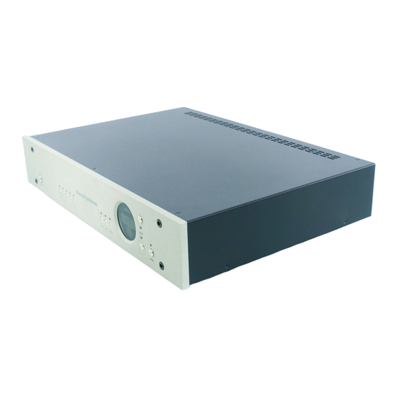
- Page 1 Conrad-Johnson Owner’s Manual PV15 Vacuum-Tube Preamplifier conrad-johnson It just sounds right.
- Page 2 Please take a few minutes to read the manual to better understand the features and capabilities of your PV15. Note that this unit is phase inverting. See the section enti- tled "Getting the most from your PV15" for details on correct hookup in your system.
- Page 3 Warranty For Conrad-Johnson Components Conrad-Johnson Design, Inc. will provide service under warranty to the original owner on products sold new in the United States for the lesser period of three years from the date of purchase by the origi- nal purchaser, or five years from the date of shipment to the au- thorized conrad-johnson dealer.
- Page 4 Be aware that requesting an estimate will delay service to your unit, as we will have to contact you for approval before commencing service. Registering The Warranty Please return the enclosed card to the factory within 30 days of purchase to register the warranty PV15 Owner’s Manual...
-
Page 5: Electromagnetic Interference (Emi)
5/- 10% of the nominal rated voltage. Electromagnetic Interference (EMI) Considerable care has been taken in the design of the PV15 to minimize its susceptibility to radio frequency interference and other forms of EMI. Choice of materials, physical layout, grounding prac-... - Page 6 Physical location and cable “dress” can be an important factor in minimizing hum pickup. The installation should situate the pream- plifier well away from the power amplifier, and power (ac mains) cords should be dressed to remain at least 4" (100mm) away from input/output cables. PV15 Owner’s Manual...
- Page 7 MAIN OUT: Connect to the input of your amplifier (or crossover in a bi-amplified system). We recommend the use of an amplifier with an input impedance of 20k ohms or higher. Since the PV15 inverts phase, it may be necessary to invert the speaker leads to maintain correct absolute phase.
- Page 8 When first connected to ac mains, or after an interruption of power, the PV15 will turn on in a default mode (after auto-muting), with the level set at 40, and the CD input selected. In subsequent sessions, as long as the ac mains has not suffered a power outage, the unit will turn on at the last used volume setting and input.
-
Page 9: Remote Control
Remote Control All operations of the PV15 can be controlled by the wireless remote unit. MUTE: Pressing the mute button will cause the main outputs to mute and the level display to be zero. Pressing it again will restore the last level setting. - Page 10 Tube Replacement The audio circuit of the PV15 uses two type 8080 miniature triode vacuum tubes. The brand of tubes we supply has been chosen by first selecting those brands which are known to be most reliable, then by extensive auditioning of these acceptable brands with the final choices being made solely on the basis of sonic performance.
-
Page 11: Absolute Phase
This will be the case if the number of phase inver- sions is even (or zero). The PV15 is phase inverting. If your system has an odd number of inversions, (for example, if the PV15 is the only phase inverting unit in the chain) then you must add one phase inversion. - Page 12 The warm up period can be expected to last about fifteen minutes. Questions: If you have questions about the installation or function of your PV15 do not hesitate to call Customer Service at (703) 698- 8581. PV15 Owner’s Manual...
- Page 13 Net Weight: 15 lb net Fuses The PV15 has two power transformers each of which is protected by a fuse. These fuses (F1 and F2) are l o cated on the main pc board near the transformers. There is also an ac mains fuse (F3) located in the ac mains inlet socket on the back of the unit.
Need help?
Do you have a question about the PV15 and is the answer not in the manual?
Questions and answers