
Related Manuals for Acer Aspire T690


Summary of Contents for Acer Aspire T690
- Page 1 Aspire T690 AcerPower FH/SK50 Service Guide Service guide files and updates are available on the AIPG/CSD web; for more information, please refer to http://csd.acer.com.tw PRINTED IN TAIWAN...
-
Page 2: Revision History
Revision History Please refer to the table below for the updates made on Aspire T690 and AcerPower FH/SK50 service guide. Date Chapter Updates... - Page 3 Copyright Copyright © 2006 by Acer Incorporated. All rights reserved. No part of this publication may be reproduced, transmitted, transcribed, stored in a retrieval system, or translated into any language or computer language, in any form or by any means, electronic, mechanical, magnetic, optical, chemical, manual or otherwise, without the prior written permission of Acer Incorporated.
- Page 4 Conventions The following conventions are used in this manual: SCREEN Denotes actual messages that appear MESSAGES on screen. NOTE Gives bits and pieces of additional information related to the current topic. WARNING Alerts you to any damage that might result from doing or not doing specific actions.
- Page 5 DIFFERENT part number code to those given in the FRU list of this printed Service Guide. You MUST use the list provided by your regional Acer office to order FRU parts for repair and service of customer machines.
-
Page 6: Table Of Contents
System Peripherals ....... . 11 Acer eRecovery ........13 Acer disc-to-disc recovery . -
Page 7: Chapter1 System Specifications
Chapter 1 System Specifications Features Processor Socket Type : Intel Socket T LGA 775 pin Processor Type : Intel Prescott 775/Smithfield/Cedar Mill/Presler/Conroe FSB 533/800 Chipset Intel 946GZ+ICH7 Form Factor : Mirco ATX Size (Max.) : 244mm x 244mm Memory Memory Type : DDRII unbuffered SDRAM module support No. - Page 8 4 pin SATA IDE connector Transfer rate support: 1.5GB/s and 3.0 GB/s Storage type support : HDD/CD-ROM/DVD-ROM/DVD-RW/DVD+RW/DVD Dual/DVD SuperMultiPlus Audio Audio Type : HD Codec Audio Channel : 7.1 channel Audio Controller /Codec : Realtek ALC888(co-lay with ALC883) Support SPDIF out/in Audio Connectors/Headers: Rear 6 jack follow HD audio definition Microphone In...
-
Page 9: Power Supply
I/O Connector Controller : Super I/O ITE 8718 Rear I/O Connector 1 PS/2 Keyboard Port, 1 PS/2 Mouse Port 1 Parallel Port, 1 Serial Port 1 VGA(CRT) Port 1 LAN Port 4 USB Ports for non-1394 sku; 4 USB ports + IEEE1394 port for 1394 sku 7.1 channel phone jack Onboard Connector 1 CPU socket... -
Page 10: Mainboard Placement
Mainboard Placement Description Name CPU Socket LGA775 socket for Intel Core 2 Duo/Pentium D/Pentium 4/Celeron D CPUs CPU_FAN1 CPU cooling fan connector DIMM1~2 DDR2 240 pin SDRAM slots FDD1 Floppy diskette drive connector ATX1 Standard 24pin ATX power connector IDE1 Primary IDE channel BIOS_WP BIOS flash protect jumper... - Page 11 Description Name CD_IN1 Analog audio input connector PCI1~2 32 bit add-on card slot PCIEX1 PCI Express x1 slot PCIEX16 PCI Express x16 slot SYS_FAN1 System fan connector R_USB Front Panel USB header ATX12V1 Auxiliary 4pin power connector Chapter 1...
-
Page 12: Block Diagram
Block Diagram PCI LAN ICH7 ALC888 SIZE : Max 2GB (Four 512Mb X 8 Double-Sided DEVICES) DEVICE IDSEL INT# REQ# GNT# PCI1 C/D/E/F PREQ-0 PGNT-0 INTEL PCI2 D/E/F/G PREQ-1 PGNT-1 P4 Processor 1394 PREQ-2 PGNT-2 PSC, Tejas - PREQ-3 PGNT-3 LGA 775 pin BW : 4.1GB/s @ FSB : 533MHz &... -
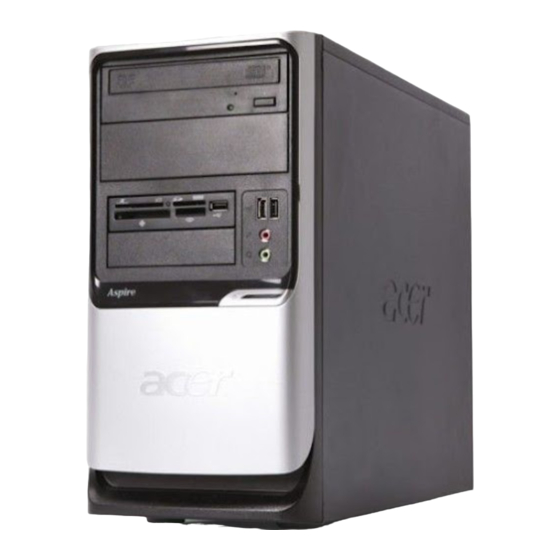
Page 13: Aspire T690 Front Panel
Aspire T690 Front Panel The computer’s front panel consists of the following: Description Label Description Description Optical drive Floppy disk drive Power button Speaker or headphone jack Microphone jack USB ports Chapter 1... -
Page 14: Aspire T690 Rear Panel
Aspire T690 Rear Panel Description Description Description Description Power cord socket Voltage selector switch Fan aperture PS/2 keyboard connector PS/2 mouse connector Serial port Printer connector Monitor connector USB 2.0 ports RJ-45 Ethernet connector Microphone jack Line-out Jack Line-in jack... -
Page 15: Acerpower Fh Front Panel
AcerPower FH Front Panel Label Description Power-Button USB ports Microphone-in & Speaker-out/Line-out Port Optical drive eject button Optical drive Indicators Card reader Chapter 1... -
Page 16: Acerpower Fh Rear Panel
AcerPower FH Rear Panel Description Description Description Description Power cord socket Voltage selector switch Fan aperture PS/2 keyboard connector PS/2 mouse connector Serial port Printer connector Monitor connector USB 2.0 ports RJ-45 Ethernet connector Microphone jack Line-out Jack Line-in jack Extension card slots Chapter 1... -
Page 17: System Peripherals
System Peripherals The Aspire S Series computer consist of the system itself, and system peripherals, like a mouse, keyboard and a set of speakers (optional). This section provides a brief description of the basic system peripherals. Mouse (PS/2 or USB, manufacturing option) The included mouse is a standard two-button wheel mouse. - Page 18 Speakers Note: For systems bundled with speakers, before powering on the system, connect the speaker cable to the audio out (external speaker) port on the back panel of the system. For more detailed information about the speakers, please refer to the included operating instructions. NOTE: speakers are optional and the appearance might be different depending on the actual product.
-
Page 19: Acer Erecovery
Acer eRecovery Acer eRecovery is a tool to quickly backup and restore the system. Users can create and save a backup of the current system configuration to hard drive, CD, or DVD. Acer eRecovery consists of the following functions: Create backup... -
Page 20: Change Password
In the Recovery settings window, select Reinstall applications/drivers and click Next. Select the desired driver/application and follow the instructions on screen to re-install. At first launch, Acer eRecovery prepares all the needed software and may take few seconds to bring up the software content window. -
Page 21: Acer Disc-To-Disc Recovery
It is important to back up all data files before you use this option. Restart the system. While the Acer logo is showing, press <Alt>+<F10> at the same time to enter the recovery process. The message "The system has password protection. Please enter 000000:" is displayed. -
Page 22: Hardware Specifications And Configurations
Hardware Specifications and Configurations Processor Item Specification Type Intel Prescott 775/Smithfield/Cedar Mill/Presler/Conroe Socket Socket T LGA 775 pin Speed System bus total up to 20.8GB/s 533/800 MHz BIOS Item Specification BIOS code programmer Award BIOS version v6.0 BIOS ROM type Flash ROM BIOS ROM size BIOS ROM package... - Page 23 System Memory Item Specification Memory slot number 2 slot Support memory size per socket 256MB to 1GB Support maximum memory size Support memory type DDR2 SDRAM Support memory interface DDR2 667/533 Support memory voltage 1.8V Support memory module package 240-pin DIMM Support to parity check feature Support to Error Correction Code (ECC) ECC checking with double-bit detect and single-bit...
- Page 24 Audio Interface Item Specification Mono or stereo Stereo Resolution support up to 24 bit Compatibility Sound Blaster Pro/16 compatible Mixed digital and analog high performance chip Enhanced stereo full duplex operation High performance audio accelerator and AC’97 support Full native DOS games compatibility Virtual FM enhances audio experience through real-time FM-to- Wavetable conversion MPU-401(UART mode) interface for wavetable synthesizers and...
- Page 25 Parallel Port Item Specification Parallel port controller ITE8718 Parallel port controller resident bus ISA bus Number of parallel ports Support ECP/EPP Bi-directional SPP / ECP / EPP V1.7&V1.9 Connector type 25-pin D-type female connector Parallel port function control Enable/disable by BIOS Setup Serial Port Item Specification...
-
Page 26: Power Management
Power Management Devices (Suspend to (Suspend to (Idle) (Shut Down) RAM) DIsk) USB Keyboard Enabled Enabled Disabled Disabled Disabled Disabled Disabled Disabled Enabled Disabled Disabled Modem (Ring) Disabled Disabled Disabled Chapter 1... -
Page 27: Power Management Function (Acpi Support Function)
Power Management Function (ACPI support function) Device Standby Mode Independent power management timer for hard disk drive devices (0-15 minutes, time step=1 minute). Hard disk drive goes into Standby mode (for ATA standard interface). Disable V-sync to control the VESA DPMS monitor. Resume method: device activated (Keyboard for DOS, keyboard &... -
Page 28: Chapter2 System Utilities
Chapter 2 System Utilities About the Setup Utility The computer uses the latest Award BIOS with support for Windows Plug and Play. The CMOS chip on the main board contains the ROM setup instructions for configuring the main board BIOS. The BIOS Setup Utility displays the system’s configuration status and provides you with options to set system parameters. -
Page 29: Entering The Setup Utility
Entering the Setup Utility When you power on the system, BIOS enters the Power-On Self-Test (POST) routines. POST is a series of built-in diagnostics performed by the BIOS. After the POST routines are completed, the following message appears: Press DEL to enter SETUP Press the delete key to have access to the BIOS Setup Utility. -
Page 30: Product Information
Product Information This option displays basic information about the system. Phoenix-AwardBIOS CMOS Setup Utility Product Information Product Name AST690/APFH/APSK50 Item Help System S/N R01-A0 Main Board ID E946GZ Menu Level Main Board S/N System BIOS Version R01-A0 SMBIOS Version BIOS Release Date Jul 27, 2006 : Move Enter: Select +/-/PU/PD:Value F10:Save ESC:Exit F1: General Help F5:Previous Values... -
Page 31: Standard Cmos Features
Standard CMOS Features Select Standard CMOS Features from the main menu to configure some basic parameters in your system. Phoenix-AwardBIOS CMOS Setup Utility Standard CMOS Features Date (mm:dd:yy) Sun, Jan 1 2006 Item Help Time (hh:mm:ss) 9 : 33 : 26 IDE Channel 0 Master [ None] Menu Level... - Page 32 IDE HDD Auto-Detection: Press <Enter> while this item is highlighted to prompt the Setup Utility to automatically detect and configure an IDE device on the IDE channel. NOTE: Press <Enter> while this item is highlighted to prompt the Setup Utility to automatically detect and configure an IDE device on the IDE channel.
-
Page 33: Advanced Bios Features
Advanced BIOS Features The following screen shows the Advanced BIOS Features. Phoenix-AwardBIOS CMOS Setup Utility Advanced BIOS Features CPU Feature [Press Enter] Item Help Hard Disk Boot Priority [Press Enter] Virus Warning [Disabled] Menu Level CPU L1 & L2 Cache [Enabled] Hyper-Threading Technology [Enabled]... - Page 34 Delay Prior to Thermal (16 Min): This item enables you to set the delay time before the CPU enters auto thermal mode. Thermal Management (Thermal Monitor 1): This item displays CPU’s temperature and enables you to set a safe temperature to Prescott CPU. TM2 Bus Ratio (12X): This item represents the frequency (bus ratio) of the throttled performance state that will be initiated when the on-die sensor goes from not hot to hot.
- Page 35 Third boot devices. Boot Up NumLock Status (On): This item defines if the keyboard NumLock key is active when your system is started. Gate A20 Option (Fast): This item defined how the system handles legacy software that was written for an earlier generation of processors. Leave this item at the default value. Typematic Rate Setting (Disabled): If this item is enabled, you can use the following two items to set the typematic rate and the typematic delay settings for your keyboard.
-
Page 36: Advanced Chipset Features
Advanced Chipset Features These items define critical timing parameters of the main board. You should leave the items on this page at their default values unless you are very familiar with the technical specifications of your system hardware. If you change the values incorrectly, you may introduce fatal errors or recurring instability into your system. Phoenix-AwardBIOS CMOS Setup Utility Advanced Chipset Feature System BIOS Cacheable... - Page 37 PCI Express Root Port Func (Press Enter): Scroll to this item and press <Enter> to view the following screen. Phoenix-AwardBIOS CMOS Setup Utility PCI Express Root Port Func PCI Express Port 1 [Auto] Item Help PCI Express Port 2 [Auto] PCI Express Port 3 [Auto] Menu Level...
-
Page 38: Integrated Peripherals
Integrated Peripherals These options display items that define the operation of peripheral components on the system’s input/output ports. Phoenix-AwardBIOS CMOS Setup Utility Integrated Peripherals Item Help OnChip IDE Device [Press Enter] Onboard Device [Press Enter] Menu Level SuperIO Device [Press Enter] : Move Enter: Select +/-/PU/PD:Value F10:Save ESC:Exit F1: General Help F5:Previous Values F7:Optimized Defaults... - Page 39 IDE DMA transfer access (Enabled): This item allows you to enable the transfer access of the IDE DMA then burst onto the PCI bus and nonburstable transactions do not. OnChip Primary/Secondary PCI IDE (Enabled): Use these items to enable or disable the PCI IDE channels that are integrated on the main board.
- Page 40 Super IO Device (Press Enter): Scroll to this item and press <Enter> to view the following screen. Phoenix-AwardBIOS CMOS Setup Utility Super IO Device Onboard FDC Controller [Enabled] Item Help Onboard Serial Port 1 [3F8/IRQ4] Onboard Serial Port 2 [2F8/IRQ3] Onboard Parallel Port [378/IRQ7] Menu Level...
-
Page 41: Power Management Setup
Power Management Setup This option lets you control system power management. The system has various power-saving modes including powering down the hard disk, turning off the video, suspending on RAM, and software power down that allows the system to be automatically resumed by certain events. Phoenix-AwardBIOS CMOS Setup Utility Power Management Setup Item Help... - Page 42 the power button down for four seconds to cause a software power down. Resume by PCI PME (Enabled): This item specifies whether the system will be awakened from power-saving modes when activity or input signal of the specified hardware peripheral or component is detected.
-
Page 43: Pnp/Pci Configurations
PnP/PCI Configurations This options configure how PnP (Plug and Play) and PCI expansion cards operate in your system. Both the ISA and PCI buses on the main board use system IRQs (Interrupt ReQuests) and DMAs (Direct Memory Access). You must set the IRQ and DMA assignments correctly through the PnP/PCI Configurations Setup utility for the main board to work properly. -
Page 44: Pc Health Status
PC Health Status On the main boards that support hardware monitoring, this item lets you monitor the parameters for critical voltages, temperatures, and fan speeds. Phoenix-AwardBIOS CMOS Setup Utility PC Health Status Item Help Smart Fan Control [Enabled] CPU Warning Temperature [70°C/158°F] Menu Level Vcore 1.20V... -
Page 45: Frequency Control
Frequency Control This item enables you to set the clock speed and system bus for your system. The clock speed and system bus are determined by the kind of processor you have installed in your system. Phoenix-AwardBIOS CMOS Setup Utility Frequency Control CPU Clock Ratio [17X]... -
Page 46: Load Optimized Defaults Option
Load Fail-Safe Defaults Option This option opens a dialog box that lets you install fail-safe defaults to all appropriate items in the Setup Utility: Press <Y> and the <Enter> to install the defaults. Press <N> and then <Enter> to not install the defaults. The Fail-Safe defaults place no great demands on the system and are generally stable. -
Page 47: Chapter3 Machine Disassembly And Replacement
Chapter 3 Machine Disassembly and Replacement To disassemble the computer, you need the following tools: Wrist grounding strap and conductive mat for preventing electrostatic discharge. Wire cutter. Phillips screwdriver (may require different size). NOTE: The screws for the different components vary in size. During the disassembly process, group the screws with the corresponding components to avoid mismatches when putting back the components. -
Page 48: General Information
General Information Before You Begin Before proceeding with the disassenbly procedure, make sure that you do the following: Turn off the power to the system and all peripherals. Unplug the AC adapter and all power and signal cables from the system. Chapter 3... -
Page 49: Disassembly Procedure
Disassembly Procedure This section tells you how to disassemble the system when you need to perform system service. Please also refer to the disassembly video, if available. CAUTION: Before you proceed, make sure you have turned off the system and all peripherals connected to it. Chapter 3... - Page 50 Aspire T690 Standard Disassembly Process 1. Open the computer. 1-1. Place the system unit on a flat, steady surface. 1-2. Turn the housing down, release the Lock-handle then slide the left side door 2. Disconnect the cables. 2-1. Disconnect the AUDIO cable.
- Page 51 Standard Disassembly Process 2-2. Disconnect the USB and Front LED ASSY cables. Front LED ASSY cable USB Cable Card-reader Cable 2-3 . Disconnect the PA and PD power-cable from the MB connector. PA power-connector PD power-connector 2-4 . Disconnect the P1 power-cable and ODD data cable from the MB connector. ODD data cable P1 power-cable...
- Page 52 Standard Disassembly Process 2-5 . Disconnect FDD data cable from the MB connector. FDD data cable 2-6 . Disconnect the ODD data cable and power-cable from the rear of ODD. ODD data cable ODD power-cable 2-7 . Disconnect the FDD data cable and power-cable from the rear of FDD. FDD data cable FDD power-cable...
- Page 53 Standard Disassembly Process 2-8 . Disconnect the HDD data cable and power-cable from the rear of HDD and MB. HDD power-cable HDD data Cable 3. Detach the HDD, FDD and ODD. 3-1. Rail the HDD-holder shown bellow, then take the HDD out from the chassis.
- Page 54 Standard Disassembly Process 3-2. Release the three latches on the front bezel, then remove the front bezel. 3-3. Rail the ODD-holder shown bellow, then take the ODD out from the chassis. 3-4. Rail the FDD-holder shown bellow, then take the FDD out from the chassis.
- Page 55 Standard Disassembly Process 3-5. Rail the Holder shown bellow, then take the Card-reader out from the chassis. 4. Detach the USB Module. Release the screw shown bellow, then take off the USB module together with the USB&Audio cable. 5. Detach the CPU Cooler. 5-1.
- Page 56 Standard Disassembly Process 5-2. Release the CPU Cooler Latch then remove it. Before revolve the Latch Pull the Latch afterward After revolve the Latch 6. Remve the Memory. Release the two latch shown bellow then remove the Memory.
- Page 57 Standard Disassembly Process 7. Remve the System Fan. Release the four screws shown bellow then take off the fan. 8. Remove the Motherboard. Release the eight screws shown bellow then take off the MB. 9. Remove the Power-supply. Release the four screws shown bellow then take off the Power-supply.
- Page 58 Standard Disassembly Process 10. Remove the CPU. Release the CPU Latch on the Socket then remove the CPU.
- Page 59 AcerPower FH " % & " &'! " ()$! ()$ &...
- Page 60 * " & + " " & $. ' $. ' & '- & & & . / & & &...
- Page 61 & . & . 0 31 0 -1...
- Page 62 0 /1 0 &1 ,2/ & < ,2/ &...
- Page 63 " " " "...
- Page 64 " & !" , - & " " * " & " &...
- Page 65 " " . / , " . / , . /5$ " '- , " " "...
- Page 66 " " " "...
-
Page 67: Chapter4 Troubleshooting
Chapter 4 Troubleshooting Please refer to generic troubleshooting guide for trougleshooting information relating to following topics: Power-On Self-Test (POST) POST Check Points POST Error Messages List Error Symptoms List Chapter 4... -
Page 68: Chapter5 Jumper And Connector Information
Chapter 5 Jumper and Connector Information Main Board Placement Label Description Label Description CPU Socket LGA775 socket for Intel CPU_FAN1 CPU cooling fan connector Core Duo / Pentium D / Pentium 4 / Celeron D CPUs DIMM1~2 DDR2 240 pin SDRAM slots FDD1 Floppy diskette drive connector... - Page 69 Label Description Label Description ATX1 Standard 24-pin ATX power IDE1 Primary IDE channel connector BIOS_WP BIOS flash protect jumper SATA1~4 Serial ATA connectors PANEL1 Front Panel switch/LED CLR_CMOS1 Clear CMOS jumper header USB3~4 Front Panel USB headers 1394a1 Onboard 1394a header COM2 Onboard Serial port header SPDIF...
-
Page 70: Jumper Setting
Jumper Setting This section explains how to set jumpers for correct configuration of the main board. Setting Jumper Use the main board jumpers to set system configuration options. Jumpers with more than one pin are numbered. When setting the jumpers, ensure that the jumper caps are placed on the correct pins. Illustration Description The illustrations show a 2-pin jumper. -
Page 71: Checking Jumper Settings
Checking Jumper Settings Jumper Type Description Setting(Default) Illustration CLR_CMOS1 3-pin CLEAR CMOS 1-2 : Normal 2-3 : Clear CMOS Before clearing the CMOS,make sure you have turned off the system. BIOS_WP 3-pin BIOS PROTECT 1-2: Write 2-3: PROTECT Chapter 5... -
Page 72: Connecting Components
Connecting Components Connect the CPU cooling fan cable to CPU_FAN1. Connect the system cooling fan connector to SYS_FAN1. Connect the case switches and indicator LEDs to the PANEL1. Connect the standard power supply connector ATX1. Connect the auxiliary case power supply connector to ATX12V1. CPU_FAN1: CPU Fan Connector Signal Name Function... -
Page 73: Front Panel Header
SYS_FAN1: System Cooling Fan Connector Signal Name Function +12V Power +12V Sense Sensor ATX1: ATX 24-pin Power Connector Signal Name Signal Name +3.3V +3.3V +3.3V -12V Ground Ground PS_ON Ground Ground PWRGD +5VSB +12V +12V +3.3V Ground ATX12V1: ATX 12V Power Connector Signal Name Ground Ground... - Page 74 Connecting the Optional Devices COM2: Onboard serial port header Signal Name Function DCDB Data Carrier Detect SINB Serial Input SOUTB UART B Serial Output DTRB UART B Data Terminal Ready Ground DSRB Data Set Ready RTSB RART B Request to Send CTSB Clear to Send Ring Indicator...
- Page 75 AUDIO2: Front Panel Audio Header Signal Name PORT 1L PORT 1R PRESENCE# PORT 2R SENSE1_RETURN SENSE_SEND PORT 2L SENSE2_RETURN 1394A1: Onboard IEEE 1394a header (optional) Signal Name Signal Name TPA+ TPB- TPA1- +12V +12V TPB+ SATA1~4: Serial ATA connectors Signal Name Signal Name Ground Ground...
- Page 76 SPDIF: SPDIF out header Signal Name Function +5VA 5V analog Power No pin SPDIF SPDIF digital output Ground CD_IN1: Auxiliary In Connector Signal Name Function AUX_R AUX In right channel Ground Ground AUX_L AUX In left channel Rear I/O Panel Connectors PS2 Mouse: Use the PS/2 mouse port to connect a PS/2 pointing device.
- Page 77 Chapter 5...
-
Page 78: Chapter6 Fru (Field Replaceable Unit) List
NOTE: To scrap or to return the defective parts, you should follow the local government ordinance or regulations on how best to dispose it, or follow the rules set by your regional Acer office on how to return it.You can access to the website for the latest Parts version http://aicsl.acer.com.tw/spl/ NOTE: The final version of SPL will be released later. -
Page 79: Exploded Diagram
Exploded Diagram Item Description Right cover Power supply Top cover Optical drive Front bezel 3.5” cover 5.25” cover Chapter 6... - Page 80 Item Description USB BKT USB board Left cover Motherboard CHASSIS Rear IO Chapter 6...
-
Page 81: Fru List
FRU List The FRU list will be updated later. Chapter 6... - Page 82 Chapter 6...
Need help?
Do you have a question about the Aspire T690 and is the answer not in the manual?
Questions and answers