Table of Contents
Advertisement
E 2012 Lennox Industries Inc.
Dallas, Texas, USA
RETAIN THESE INSTRUCTIONS
FOR FUTURE REFERENCE
IMPORTANT
This unit must be serviced annually by a licensed
professional technician, or equivalent.
WARNING
Improper installation, adjustment, alteration, ser-
vice, or maintenance can cause injury or property
damage. Refer to this manual. For assistance or
additional information, consult a licensed profes-
sional installer, or equivalent, or service agency.
WARNING
Do not store or use gasoline or other flammable va-
pors and liquids in the vicinity of this or any other ap-
pliance.
CAUTION
When venting this appliance, keep vent terminal free
of snow, ice and debris.
CAUTION
As with any mechanical equipment, personal injury
can result from contact with sharp sheet metal
edges. Be careful when you handle this equipment.
04/12
*2P0412*
INSTALLATION
INSTRUCTIONS
ELO183UF SERIES UNITS
OIL UNITS
506901−01
04/2012
Table of Contents
. . . . . . . . . . . . . . . . . . . . . . . . . . . . . . . . . . . . .
. . . . . . . . . . . . . . . . . . . . . . . . . . . . . . . .
. . . . . . . . . . . . . . . . . . . . . . . . . . . . . .
. . . . . . . . . . . . . . . . . . . . . . . . . . . . . . . . .
. . . . . . . . . . . . . . . . . . . . . . . . . . . . . . . . . . . . .
. . . . . . . . . . . . . . . . . . . . . . . . . . . . . . . .
. . . . . . . . . . . . . . . . . . . . . . . . . . . . .
. . . . . . . . . . . . . . . . . . . . . . . . . . . . . . . . . . . .
. . . . . . . . . . . . . . . . . . . . . . . . . . . . .
General
These instructions are intended as a general guide and do
not supersede local codes in any way. Only licensed pro-
fessional technicians, or equivalent, can install and service
®
the Lennox Elite
Series ELO183UF oil furnaces. In Cana-
da, refer to CSA B139 for recommended installation proce-
dures. Consult authorities who have jurisdiction before
installation.
Never burn garbage or paper in the heating system.
Never leave papers near or around the unit.
Shipping & Packing List
1 − Assembled oil furnace
1 − Barometric draft control
1 − Oil nozzle (used with ELO183UF−86, −114 and −150
only)
Check the components for shipping damage. If you find any
damage, immediately contact the last carrier.
Page 1
. . . . . . . . . . . . . . . . . . . . . . . . . .
. . . . . . . . . . . . . . . . . . . . .
. . . . . . . . . . . . . . . .
. . . . . . . . .
. . . . . . . . . . . . . . . . . . . . . . .
. . . . . . . . . . . . . . . . . . . . . . . .
. . . . . . . . . . . . . . . . . . . . . . . . . . . .
. . . . . . . . . . . . . . . . .
. . . . . . . . . . . . . . . . . . . . . . . .
. . . . . . . . . . .
. . . . . . . . . . . . . . . . . .
CAUTION
506901−01
*P506901-01*
Litho U.S.A.
1
1
2
. .
2
3
3
4
5
6
7
8
8
9
10
10
12
12
12
14
16
18
Advertisement
Table of Contents

Related Manuals for Lennox ELO183UF Series


Summary of Contents for Lennox ELO183UF Series
-
Page 1: Table Of Contents
INSTALLATION INSTRUCTIONS E 2012 Lennox Industries Inc. Dallas, Texas, USA ELO183UF SERIES UNITS OIL UNITS Litho U.S.A. 506901−01 04/2012 Table of Contents General ........ -
Page 2: Elo183Uf Unit Dimensions
ELO183UF Unit Dimensions − Inches (mm) (19) (19) TOP FLUE OUTLET SUPPLY OPENING TOP VIEW FLUE CONNECTION (On Heat Exchanger) SIDE FLUE OUTLET CENTERING HOLE (Field Fabricate Either Side) ELECTRICAL INLET (Right Side Only) (1372) OIL PIPING INLET (Left Side Only) 1-1/2 AIR FLOW OPT. -
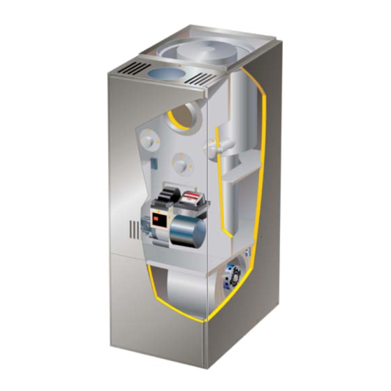
Page 3: Elo183Uf Unit Parts Arrangement
ELO183UF Unit Parts Arrangement Heat Exchanger Flue Opening Clean-out Port Limit Switch Clean−out Port ST9103 Burner Control Observation Port Beckettr AFG Burner Indoor Blower Figure 1 ELO183UF AFG Oil Burner Parts Arrangement BURNER CONTROL (with Reset Button) IGNITER MAIN ESCUTCHEON HOUSING PLATE HEAT... -
Page 4: Requirements
0 (0) 0 (0) agency. cabinet rear 0 (0) 0 (0) Installation of Lennox oil−fired furnaces must conform with cabinet front 4 (120) 4 (120) the National Fire Protection Association Standard for the top of plenum and duct 2 (51) 2 (51) Installation of Oil Burning Equipment, NFPA No. -
Page 5: Combustion Air
trol the flow of air) shall be adequate to prevent chilled air from vided to meet the needs of all fuel-burning appliances, as entering the furnace and, if manually operated, must be well as appliances such as exhaust fans which force air out equipped with means to prevent operation of either unit, un- of the home. -
Page 6: Locate & Level The Unit
When ducts are used, they shall be of the same cross−sec- Equipment In Confined Space tional area as the free area of the openings to which they All Air From Inside connect. The minimum dimension of rectangular air ducts Chimney or Oil Ven shall be no less than 3"... -
Page 7: Adjustments
ELO183UF Series Burner Removal floor. Make sure the weight of the furnace is distributed First, loosen three nuts which Next, rotate burner clockwise evenly on all four corners. -
Page 8: Indoor Coil Placement
Indoor Coil Placement let diameter of the vent outlet of the furnace. In cooling / heat pump applications, Lennox recommends that 4 − Pipe should be at least 24 gauge galvanized. the indoor coil be installed at least 4 inches above the top of the 5 −... -
Page 9: Flue Connections
18 − Keep the area around the vent terminal free of snow, Factory−Built Chimney ice and debris. NOTE − If vent pipe needs to exit from side of cabinet, use the pilot hole (located on either side of the unit) to Barometric Draft Factory−... -
Page 10: Supply & Return Air Plenums
Alternate Side Flue Connections Radiation Shield Installation combustible The vent pipe may exit the top or sides of the cabinet. A É É É É É É É É material hole is provided in the top cap for top exit. For side exit, lo- É... - Page 11 To determine the correct tubing size for piping, refer to table 3. Use continuous lengths of heavy wall copper tubing or steel pipe for oil supply pipe. Install oil supply pipe under Table 3 floor or near walls to protect it from damage. Avoid running One−Pipe Oil Line Sizing pipes along joists or reverberating surfaces.
-
Page 12: Oil Supply Line & Filter Connections
4 − The return pipe must terminate 3" to 4" above the sup- Oil Supply Line & Filter Connections ply pipe inlet. See figure 13. One−Pipe Systems NOTE − If the return pipe does not terminate where it should, air may enter the system, and prime may be CAUTION lost. - Page 13 4 − Complete line voltage wiring from disconnect switch CAUTION near unit to make-up box. NOTE − An equipment ground screw is provided. Refer Use copper conductors only. to unit wiring diagram. Ground unit using a suitable IMPORTANT ground wire. 5 −...
-
Page 14: Unit Start-Up & Adjustments
6 − Repeat steps 4 and 5, if necessary, until pump is fully Unit Start−Up & Adjustments primed and oil is free of bubbles. Then, terminate the Before starting unit, make sure the oil tank is adequately call for heat. The burner control will resume normal op- filled with clean No. - Page 15 The following instructions are essential to the proper op- adjust the air band to increase the air. To adjust the air eration of ELO183UF series oil furnaces. To prevent soot- band, loosen the air band screw and rotate the ing, these instructions must be followed in sequence: band.This is the starting point.
-
Page 16: Service
NOTE − A heat exchanger clean-out kit ABRSH380 filter when dry. Permanent filters supplied with ELO183UF (35K09) is available from Lennox. The kit includes a ra- furnaces do not require oiling after cleaning. Examine filter diator brush, a tapered brush and a non−metallic 36"... - Page 17 GeniSyst Primary Burner Control ELO183UF units are equipped with the Beckett GeniSyst 7505B primary burner control. The control is positioned on the upper right−hand side of the Beckett AFG burner assembly. The control includes a reset button and three status lights. See figure 16 for location of reset buttons and status lights.
-
Page 18: Troubleshooting
After soft lockout reset, oil primary control allows Heating Sequence − Actions & Responses second ignition attempt. Primary control enters hard lockout after second ignition failure (15 sec- 1. Action: Thermostat calls for heat (W terminal is en- onds without flame being sensed). Push reset but- ergized) ton on primary control for 15 seconds until light on Response:... - Page 19 Troubleshooting: Fan operating sequence Action System Response Thermostat calls for heat. Oil primary control is energized. (W terminal is energized.) Ignition system and oil primary control start the furnace. Oil flows as long as cad cell senses flame. Burner motor is energized and heat fan on delay timing (1 to 30 seconds) begins. When timing is complete, the circulating fan is energized at heat speed and warm air is deliv- ered to the controlled space.
- Page 20 Troubleshooting: Burner fails to start. Source Procedure Causes Correction Thermostat in OFF or COOL Switch to HEAT. Thermostat Check thermostat settings. Turn thermostat to higher tem- Thermostat is set too low perature. Burner motor overload tripped Push reset button pump motor. Primary control tripped on safe- Check burner motor, primary Reset primary control.
- Page 21 Troubleshooting: Burner starts, but no flame is established. Source Procedure Causes Correction Check tank gauge or use dip No oil in tank Fill tank. stick. Coat dip stick with litmus paste If water depth exceeds 1 inch, Oil Supply Water in oil tank and insert into bottom of tank.
- Page 22 Troubleshooting: Burner starts and fires, but lock out on safety. Source Procedure Causes Correction Unbalanced fire Replace nozzle Reduce combustion air − check Too much air − −lean short fire If burner con- combustion. tinues to run, Increase combustion air − check this may be Too little air −...
- Page 23 Troubleshooting: Burner starts and fires, but short cycles (too little heat) Source Procedure Causes Correction Heat anticipator set too low Correct heat anticipator setting. Vibration at thermostat Correct source of vibration. Thermostat Check thermostat. Thermostat in the path of a Shield thermostat from draft or warm air draft relocate.
- Page 24 Troubleshooting: Burner runs continuously (too little heat). Source Procedure Causes Correction Too much combustion air Reduce combustion air. Air leaks into heat exchanger Correct cause of air leak. around inspection door, etc. Low CO less Adjust barometric draft con- than 10%. Excessive overfire draft trol for correct draft.
Need help?
Do you have a question about the ELO183UF Series and is the answer not in the manual?
Questions and answers