
Related Manuals for Acer TravelMate 6592G


Summary of Contents for Acer TravelMate 6592G
- Page 1 TravelMate 6592/6592G Service Guide Service guide files and updates are available on the ACER/CSD web; for more information, please refer to http://csd.acer.com.tw PRINTED IN TAIWAN...
-
Page 2: Revision History
Revision History Please refer to the table below for the updates made on TravelMate 6592/6592G service guide. Date Chapter Updates... - Page 3 Copyright Copyright © 2007 by Acer Incorporated. All rights reserved. No part of this publication may be reproduced, transmitted, transcribed, stored in a retrieval system, or translated into any language or computer language, in any form or by any means, electronic, mechanical, magnetic, optical, chemical, manual or otherwise, without the prior written permission of Acer Incorporated.
- Page 4 Conventions The following conventions are used in this manual: SCREEN MESSAGES NOTE WARNING CAUTION IMPORTANT Denotes actual messages that appear on screen. Gives bits and pieces of additional information related to the current topic. Alerts you to any damage that might result from doing or not doing specific actions.
- Page 5 DIFFERENT part number code to those given in the FRU list of this printed Service Guide. You MUST use the list provided by your regional Acer office to order FRU parts for repair and service of customer machines.
-
Page 7: Table Of Contents
Acer Empowering Technology ........ - Page 8 Removing the Battery Pack ...61 Removing the Cover Securing Screws and Covers ...61 Removing the HDD ...62 Removing the Memory Module ...63 Removing the Wireless Card ...64 Removing the ODD ...65 Removing Dummy Trays ...65 Removing the Switch Cover ...66 Removing the Keyboard ...67 Disconnecting the TouchPad ...69 Removing the Switch Board ...70...
- Page 9 Index of Error Messages ..........103 Phoenix BIOS Beep Codes .
-
Page 11: Chapter 1 System Specifications
Display and graphics 20.1” WSXGA+ high-brightness Acer CrystalBrite lamps 19” WXGA+ high-brightness Acer CrystalBrite 16 ms typical of/off and 8 ms average gray-to-gray response time Simultaneous multi-window viewing via Acer Vista ® ® NVIDIA GeForce VRAM and up to 256 MB of shared system memory) or, ®... - Page 12 Mini DIN cable: RCA jack and S-video port for audio/video input • Acer DVB-T antenna (UHF/VHF reception) supporting Acer SignaUp Audio Audio system with two built-in Acer 3DSonic (1.5W) stereo speakers and one Acer BasSonic Subwoofer ® Dolby Digital Live and DTS Neo: PC support ®...
- Page 13 Modem: 56K ITU V.92 modem with PTT approval; wake-on ring ready LAN: gigabit Ethernet; wake-on-LAN ready WPAN: Bluetooth® 1.1 @ 723 bps Optional WLAN:ICH6-M (dual-band tri-mode 802.11a/b/g) Wi-Fi® CERTIFIEDTM solution, supporting Acer SignalUpTM wireless technology I/O Ports CRT port --- Suport CRT monitor. 3 * USB 2.0/1.1 ports...
-
Page 14: System Block Diagram
System Block Diagram Chapter 1... -
Page 15: Mainboard Layout
Mainboard Layout Top View JACK1 AV-in Jack TV Antenna Connector S-Video Connector CN509 Card Bus Socket S-Video Connector HDMI Connector Video Memory I/O Board to Main Board Connector Video Memory DVI-D Port Graphic Controller DDR2 SDRAM IC DDR2 SDRAM IC JACK2 Microphone Jack Ethernet Controller... -
Page 16: Bottom View
CN14 DIMM Socket CN18 Optical Disk Drive Connector South Bridge Bottom View U504 LAN Transformer GSN 5009 CN502 Launch Board Connector U503 Video Memory U502 Video Memory CN4002 LCD Connector CN3000 Hotkey Board Connector CN503 Express Card Slot CN507 DDR2 SDRAM IC CN11 IEEE port PCI cardbus/Media Board/1394 IC... -
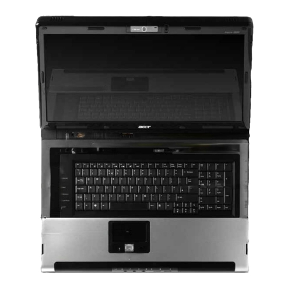
Page 17: Your Acer Notebook Tour
1.3 megapixel web camera for video communication. Display screen Also called Liquid-Crystal Display (LCD), displays computer output. Media/volume buttons For use with Acer Arcade and other mdeia playing programs. Microphone Internal microphone for sound recording. Touchpad Touch-sensitive pointing device which functions like a computer mouse. -
Page 18: Closed Front View
10/11 Closed Front View Icon Speaker Infrared port/CIR receiver Line-in jack Microphone-in jack Headphones/speaker/ line-out jack with S/ PDIF support Power indicator Battery indicator Bluetooth communication button/ indicator Wireless communication button/ indicator Easy-launch buttons Buttons for launching frequently used programs. Power button Turns the computer on and off. -
Page 19: Left View
Left View Icon Right View Icon Chapter 1 Item USB 2.0 ports Connects to USB 2.0 devices (e.g., USB mouse, USB camera). Modem (RJ-11) port Connects to a phone line. Optical drive Internal optical drive; accepts CDs or DVDs (slot-load or tray-load depending on model). -
Page 20: Rear View
Rear view Icon 3 USB 2.0 ports Connect to USB 2.0 devices (e.g., USB mouse, USB camera). 4-pin IEEE 1394 port Connects to IEEE 1394 devices. PC Card slot eject Ejects the PC Card from the slot. button PC Card slot Accepts one Type II PC Card. -
Page 21: Base View
Icon Base view Item Ventilation slots and cooling fan Chapter 1 Item Ventilation slots Enable the computer to stay cool, even after prolonged use. S-video/TV-out Connects to a television or display (NTSC/PAL) port device with S-video input. External display Connects to a display device (e.g., (VGA) port external monitor, LCD projector). -
Page 22: Indicators
Memory compartment Battery lock Battery release latch Battery bay Hard disk bay Sub woofer Indicators The computer has several easy-to-read status indicators. The front panel indicators are visible even when the computer cover is closed up. Icon Function Standby Cap lock Num lock Power Houses the computer’s main memory. -
Page 23: Easy-Launch Buttons
Web browser, Empowering Key “ Press “ “ to run the Acer Empowering Technology. The mail and Web browser buttons are pre-set to email and Internet programs, but can be reset by users. To set the Web browser, mail and programmable buttons, run the Acer Launch Manager. -
Page 24: Touchpad Basics
Touchpad Basics The following teaches you how to use the touchpad: Move your finger across the touchpad (2) to move the cursor. Press the left (1) and right (4) buttons located beneath the touchpad to perform selection and execution functions. These two buttons are similar to the left and right buttons on a mouse. Tapping on the touchpad is the same as clicking the left button. -
Page 25: Using The Keyboard
Using the Keyboard The keyboard has full-sized keys and an embedded keypad, separate cursor keys, two Windows keys and twelve function keys. Lock Keys and embedded numeric keypad The keyboard has three lock keys which you can toggle on and off. Lock Key Caps Lock When Caps Lock is on, all alphabetic characters typed... -
Page 26: Hot Keys
Function Hot key help Displays help on hot keys. Acer eSetting Launches the Acer eSettings in Acer eManager. Acer Launches the Acer ePowerManagement in Acer ePowerManagement Empowering Technology. See “Acer Empowering Technology” on page 19. -
Page 27: Special Key
Hot Key Icon <Fn>+<F4> <Fn>+<F5> <Fn>+<F6> <Fn>+<F7> <Fn>+<F8> <Fn>+<w> <Fn>+<y> <Fn>+<-x> <Fn>+<z> Special Key You can locate the Euro symbol and US dollar sign at the upper-center and/or bottom-right of your keyboard. To type: The Euro symbol 1. Open a text editor or word processor. Chapter 1 Function Sleep... - Page 28 Either directly press the < press the<5> symbol at the upper-center of the keyboard. NOTE: Some fonts and software do not support the Euro symbol. Please refer to www.microsoft.com/ typography/faq/faq12.htm for more information. The US dollar sign 1. Open a text editor or word processor. Either directly press the <...
-
Page 29: Acer Empowering Technology
Help function. Acer eDataSecurity Management Acer eDataSecurity Management is handy file encryption utility that protexts your files from being accessed by unauthorized persons. It is conveniently integrated with Windows explorer as a shell extension for quick and Chapter 1 >... - Page 30 easy data encryption/decryption and also supports on-the-fly file encryption for MSN Messager and Microsoft Outlook. There are two passwords that can be used to encrypt/decrypt a file; the supervisor passowrd and the file- specific password. The supervisor passwork is a “master” password that cna decrypt any file on your system; the file-specific password will be used to encrypt files by default, or you cna choose to enter your own file- specific password when encrypting a file.
-
Page 31: Acer Elock Management
Floppy disk drives - 3.5-inch disks only. To activate Acer eLock Management, a password must be set first. Once set, you may apply lock to any of the three kinds of devices. Lock(s) will immediately be set without any reboot necessary, and will remain locked after rebooting, until unlocked. -
Page 32: Acer Eperformance Management
Acer ePerformance Management Acer ePerformance Management is a system optimization tool that boosts the performance of your Acer notebook. It provides you with the following options to enhance overall system performance: Memory optimization - releases unused memory and check usage. -
Page 33: Acer Erecovery Management
Acer eRecovery Management Acer eRecovery Management is a powerful utility that does away with the need for recovery disks provided by the manufacturer. The Acer eRecovery Management utility occupies space in a hidden partition on your system’s HDD. User-created backups are stored on D:\ drive. Acer eRecovery Management provides you with: Password protection. -
Page 34: Acer Esettings Management
NOTE: If your computer did not come with a Recovery CD or System CD, please use Acer eRecovery Management’s “System backup to optical disk” feature to burn a backup image to CD or DVD. To ensure the best results when recovering your system using a CD or Acer eRecovery Management, detach all peripherals (except the external Acer ODD, if your computer has one), including your Acer ezDock. -
Page 35: Acer Epower Management
Acer ePower Management Acer ePower Management features a straightforward user interface. To launch it, select Acer ePower Management from the Empowering Technology interface, or double-click the Acer ePower Management icon in the task tray. Acer Mode The default setting is “Maximum Performance.” You can adjust CPU speed, LCD brightness and other settings, or click on buttons to turn the following functions on/off: Wireless LAN, Bluetooth, CardBus, Memory Card, Audio, and Wired LAN. - Page 36 You can also click “Advanced Settings” to: Set alarms. Re-load factory defaults. Select what actions will be taken when the cover is closed, and set passwords for accessing the system after Hibernation or Standby. View information about Acer ePower Management. Chapter 1...
- Page 37 Acer ePresentation Management Acer ePresentation Management lets you select from two of the most common projector resolutions: XGA and SVGA. Chapter 1...
-
Page 38: Acer Orbicam
Acer OrbiCam The Acer OrbiCam is a 1.3 megapixel CMOS camera appropriately mounted on the top of the LCD panel. The camera’s 225-degree ergonomic rotation allows you to capture high-resolution photos or videos up front or at the back of the LCD panel. The Acer OrbiCam fully supports the Acer Video Conference technology so that you can transmit the best video quality over an instant Messenger service. - Page 39 Changing the Acer OrbiCam settings Resolution To change the capture resolution, click the displayed resolution at the bottom right corner of the capture window, then select the desired resolution. Options Click Options to display the Window, Preview, and Folder tabs. Use the options to change the capture window size, preview settings, and the folder for captured photos or videos.
- Page 40 Capturing photos or videos To capture a photo or a video clip, rotate the Acer OrbiCam to get the desired angle, then click the Take a Picture or Record a Video button. The Windows Picture and Fax Viewer or the Windows Media Player automatically launches to display or play a preview of the photo/video clip.
- Page 41 The VisageON window appears as below: Select and apply a video effect in the left section of the VisageON window. Change the face tracking settings and options in the right section. Using the face tracking feature To use the face tracking feature: 1.
- Page 42 Using video effects (selected models only) The Video Settings section allows you to select an avatar or accessory video effect from the list. To select an effect: 1. Click the encircled icon to display the available video effects. The Video Effect Selection window appears as below: Click on a video effect to use.
-
Page 43: Using The System Utilities
Apply to confirm the new settings and click OK to complete the process. Acer GridVista is a handy utility that offers four pre-defined display settings so you can view multiple windows on the same screen. To access this function, please go to Start>All Programs and click on Acer GridVista. -
Page 44: Launch Manager
NOTE: Please ensure that the resolution setting of the second monitor is set to the manufacturer's recommended value. Launch Manager Launch Manager allows you to set the four easy-launch buttons located above the keyboard. You can access the Launch Manager by clicking on Start > All Programs > Launch Manager to start the application. Chapter 1... -
Page 45: Hardware Specifications And Configurations
Hardware Specifications and Configurations Processor Item CPU type Core logic CPU package CPU core voltage CPU Fan True Value Table CPU Temperature Core 0 Core 1 BIOS Item BIOS vendor BIOS Version BIOS ROM type BIOS ROM size BIOS package Supported protocols BIOS password control NOTE: If you need to check PXE version, press F2 to enter BIOS then enable boot from LAN function. - Page 46 System Memory Item Memory controller Memory size DIMM socket number Supports memory size per socket Supports maximum memory size Supports DIMM type Supports DIMM Speed Supports DIMM voltage Supports DIMM package Memory module combinations Memory Combinations Slot 1 128MB 128MB 128MB 128MB 256MB...
- Page 47 LAN Interface Item Features Modem Interface Item Data modem data baud rate (bps) Supports modem protocol Modem connector type Modem connector location Bluetooth Interface Item Chipset Data throughput Protocol Interface Connector type Wireless Module 802.11b/g (optional device) Item Chipset Data throughput Protocol Interface Hard Disk Drive Interface...
- Page 48 Hard Disk Drive Interface Item Interface ATA/ATAPI-6; ATA-6 Max. media transfer rate (disk-buffer, Mbytes/s) Data transfer 100 MB/Sec. rate Ultra DMA mode-5 (host~buffer, Mbytes/s) DC Power Requirements Voltage 5V(DC) +/- 5% tolerance Combo Drive Interface Item Vendor & model name Performance Specification Transfer rate (KB/sec) Buffer Memory...
- Page 49 DVD-Dual Interface Item Applicable disc format Loading mechanism Power Requirement Input Voltage Audio Interface Item Audio Controller Audio onboard or optional Mono or Stereo Resolution Compatibility Mixed sound source Voice channel Sampling rate Internal microphone Internal speaker / Quantity Video Interface Item Chipset Package...
- Page 50 USB Port Item Chipset USB Compliancy Level OHCI Number of USB port Location Serial port function control PCMCIA Port Item PCMCIA controller Supports card type Number of slots Access location Supports ZV (Zoomed Video) port Supports 32 bit CardBus System Board Major Chips Item Core logic USB 2.0...
- Page 51 Battery Item Vendor & model name Battery Type Pack capacity Number of battery cell Package configuration Normal voltage Charge voltage LCD 14.1 inch Item Vendor & model name Screen Diagonal (mm) Active Area (mm) Display resolution (pixels) Pixel Pitch Pixel Arrangement Display Mode Typical White Luminance (cd/m also called Brightness...
- Page 52 LCD 14.1 inch Item Viewing Angle (degree) Horizontal: Right/Left Vertial: Upper/Lower Temperature Range(°C) Operating Storage (shipping) LCD Inverter Item Vendor & model name Brightness conditions Input voltage (V) Input current (mA) Output voltage (V, rms) Output current (mA, rms) Output voltage frequency (k Hz) AC Adaptor Item Input rating...
-
Page 53: Chapter 2 System Utilities
Phoenix TrustedCore Setup Utility Exit Genuine Intel ® CPU XXXXGHz Intel Raid0 TSST CorpCD MK3018GAP-(PM) Y2554027T Slimtype DVD-ROM LSD-081-(S V1.0 ATI M9+XC V0.1 XXXXXXXXXX XXXXXXXXXX TravelMate XXXX Acer Inc. XXXXXXXXXX F5: Previous Values F7: Optimized Defaults Chapter 2 Help Item Menu Level... -
Page 54: Navigating The Bios Utility
Navigating the BIOS Utility There are six menu options: Info., Main, System Devices, Security, Boot, and Exit. Follow these instructions: To choose a menu, use the cursor left/right keys (zx). To choose a parameter, use the cursor up/down keys ( wy). To change the value of a parameter, press por q. -
Page 55: Information
Phoenix TrustedCore Setup Utility Information Genuine Intel ® CPU XXXXGHz Intel Raid0 TSST CorpCD MK3018GAP-(PM) Y2554027T Slimtype DVD-ROM LSD-081-(S V1.0 ATI M9+XC V0.1 XXXXXXXXXX XXXXXXXXXX TravelMate XXXX Acer Inc. XXXXXXXXXX F5: Previous Values F7: Optimized Defaults Description Help Item Menu Level... -
Page 56: Main
Main The Main screen displays a summary of your computer hardware information, and also includes basic setup parameters. It allows the user to specify standard IBM PC AT system parameters. NOTE: The screen below is for reference only. Actual values may differ. Phoenix - Award WorkstationBIOS CMOS Setup Utility System Time System Date... - Page 57 The table below describes the parameters in this screen. Settings in boldface are the default and suggested parameter settings. Parameter System Time Sets the system time. The hours are displayed with 24-hour format System Date Sets the system date System Memory This field reports the memory size of the system.
-
Page 58: Advanced
Advanced The Advanced screen displays advanced settings in BIOS. Phoenix - Award WorkstationBIOS CMOS Setup Utility Serial Port Infrared Port (FIR) Parallel Port Mode ASF Configuration Minimum Watchdog Timeout BIOS Boot Timeout OS Boot Timeout Power-on wait Time :Move Enter: Select +/-/PU/PD :Value F10: Save and Exit ESC:Exit F1: General Help The table below describes the parameters in this screen. -
Page 59: Security
Security The Security screen contains parameters that help safeguard and protect your computer from unauthorized use. Phoenix - Award WorkstationBIOS CMOS Setup Utility Supervisor Password Is User Password Is HDD Password Is Set Supervisor Password Set User Password Set HDD Password Password on Boot Current TPM State Change TPM State... - Page 60 The table below describes the parameters in this screen. Settings in boldface are the default and suggested parameter settings. Parameter Supervisor Password Is User Password Is HDD Passwored Is Set Supervisor Password Set User Password Set HDD Password Password on Boot Current TPM State Change TPM State NOTE: When you are prompted to enter a password, you have three tries before the system halts.
-
Page 61: Removing A Password
Symbol Character The maximum cycles to retry password is limited to 3. User cannot change/remove password during resuming from S4. Finger print: support 10 fingers - Upack/Authentec modules. Setting a Password Perform the following steps to set the supervisor, user, or HDD password. NOTE: The following example uses the Supervisor Password screens. -
Page 62: Changing A Password
Changing a Password Use the keys to highlight the Set Supervisor Password parameter and press the Enter key. The Set Password box appears: Type the current password in the Enter Current Password field and press Enter. Type a password in the Enter New Password field. Retype the password in the Confirm New Password field. - Page 63 Chapter 2...
-
Page 64: Boot
Boot This menu allows the user to decide the order of boot devices to load the operating system. Bootable devices includes the distette drive in module bay, the onboard hard disk drive and the CD-ROM in module bay. Phoenix - Award WorkstationBIOS CMOS Setup Utility Boot Priority Order: 1: IDE0: WDC WD200EB - (PM) 2: IDE1: WDC WD200EB - (PM) -
Page 65: Exit
Exit The Exit screen contains parameters that help safeguard and protect your computer from unauthorized use. Phoenix - Award WorkstationBIOS CMOS Setup Utility Exit Saving Changes Exit Discarding Changes Load Setup Defaults Discard Changes Save Changes :Move Enter: Select +/-/PU/PD :Value F10: Save and Exit ESC:Exit F1: General Help The table below describes the parameters in this screen. -
Page 66: Bios Flash Utility
BIOS Flash Utility The BIOS flash memory update is required for the following conditions: New versions of system programs New features or options Restore a BIOS when it becomes corrupted. Use the Phlash utility to update the system BIOS flash ROM. NOTE: If you do not have a crisis recovery diskette at hand, then you should create a Crisis Recovery Diskette before you use the Phlash utility. -
Page 67: Machine Disassembly And Replacement
Machine Disassembly and Replacement This chapter contains step-by-step procedures on how to disassemble the notebook computer for maintenance and troubleshooting. To disassemble the computer, you need the following tools: Wrist grounding strap and conductive mat for preventing electrostatic discharge Small Philips screw driver Philips screwdriver Plastic flat head screw driver Tweezers... -
Page 68: General Information
General Information Before You Begin Before proceeding with the disassembly procedure, make sure that you do the following: Turn off the power to the system and all peripherals. Unplug the AC adapter and all power and signal cables from the system. Chapter 3... -
Page 69: Disassembly Procedure Flowcharts
Disassembly Procedure Flowcharts The following flowcharts give you a graphic representation on the entire disassembly sequence and instructs you on the components that need to be removed during servicing. For example, if you want to remove the system board, you must first remove the keyboard, then disassemble the inside assembly frame in that order. Main Unit Disassembly Flowchart Chapter 3... -
Page 70: Lcm Module Disassembly Flowchart
LCM Module Disassembly Flowchart Chapter 3... -
Page 71: Main Unit Disassembly Procedure
Main Unit Disassembly Procedure Removing the Battery Pack Turn the computer over. Release the battery lock as shown. Push the release latch, the battery pops up. Remove the battery. Removing the Cover Securing Screws and Covers Locate and loosen the seventeen (17) screws as shown. NOTE: It is not necessary to remove the screws from the cover. -
Page 72: Removing The Hdd
Locate and remove the memory and HDD cover screws as shown. Remove the memory cover as shown. Remove the HDD cover as shown. Removing the HDD Locate the plastic tab on the HDD. Chapter 3... -
Page 73: Removing The Memory Module
Place one hand on the computer for stability and grasp the HDD removal tag. Pull away from the connector and upward as shown to remove the HDD from the chassis. Removing the Memory Module Push the two release levers on the memory module outward as shown. NOTE: The memory module lifts upward during release. -
Page 74: Removing The Wireless Card
Removing the Wireless Card NOTE: Fine tweezers are required for this procedure. Locate the three antenna wires (white tape, red tape and no tape) on the left-hand side of the memory bay. Using fine tweezers, grip the white taped wire and pull upward until it is released from the board. Repeat for the red taped and no tape wires. -
Page 75: Removing The Odd
Removing the ODD Push and hold the ODD latch as shown. Remove ODD. Removing Dummy Trays Locate Dummy Tray 1 and press the cover inwards as shown. Remove Dummy Tray 1 Chapter 3... -
Page 76: Removing The Switch Cover
Locate Dummy Tray 2 and press the release button as shown. Remove Dummy Tray 2. Removing the Switch Cover CAUTION: Using tools to remove the Switch Cover may cause damage to the outer casing. It is recommended that only fingers are used to remove the Switch Cover. Turn the computer over. -
Page 77: Removing The Keyboard
Using two hands, remove the Switch Cover from the chassis. Removing the Keyboard Locate and remove the two screws as shown. Using both hands, lift the top edge of the keyboard as shown. Turn the keyboard over, as shown, to expose the cables. Chapter 3... - Page 78 Using fine tweezers, release the first cable lock as shown and remove the cable from the socket. Using fine tweezers, release the second cable lock as shown and remove the cable from the socket. Remove keyboard from chassis. Chapter 3...
-
Page 79: Disconnecting The Touchpad
Disconnecting the TouchPad Disconnect the first cable by releasing the locking latch and removing the cable as shown. Disconnect the second cable by releasing the locking latch and removing the cable as shown. NOTE: Move the cable away from the work area to allow access to the third cable. Disconnect the third cable as shown. -
Page 80: Removing The Switch Board
Removing the Switch Board Locate and remove the two screws as shown. Remove the Switch Board from the chassis. Removing the Modem Module Disconnect the two cables from the Modem Module as shown. Chapter 3... -
Page 81: Removing The Antenna Cables
Locate and remove the two securing screws as shown. Lift the Modem Module clear of the chassis. Removing the Antenna Cables Remove the Antenna Cables from the securing pins as shown. Pull the three Antenna Cables from the underside of the computer through the mainboard as shown. Chapter 3... -
Page 82: Removing The Lcm Module
Removing the LCM Module CAUTION: Ensure all cables are removed from securing pins before proceeding to avoid damage. Disconnect the LCM Module cable as shown. Locate and remove the four screws as shown. Lift the LCM Module upward to remove from the chassis. Removing the TouchPad Lift the rear edge of the TouchPad Module first, as shown, then pull the module away from the mounting to clear the ports at the front of the computer. -
Page 83: Removing The Mainboard
Removing the Mainboard Locate the three connectors (yellow markers) as shown. Disconnect the connectors using tweezers as shown. Locate and remove the two screws as shown to release the Mainboard. Chapter 3... -
Page 84: Removing The I/O Board
Grip the mainboard from the front and lift up. NOTE: If any resistance is met while removing the mainboard, ease the computer case outward to clear the obstruction. Lift the mainboard clear of the chassis. Removing the I/O Board Locate and remove the two screws as shown. Lift the board toward the front of the computer to clear the port and remove from the chassis. -
Page 85: Removing The Heatsink And Fan Module
Removing the Heatsink and Fan Module Turn the mainboard over. Locate and remove the five screws (red markers) and fan connector (yellow marker) from the mainboard. Remove the Heatsink securing bracket as shown. Remove the Heatsink as shown. Steady the Mainboard with one hand and remove the Fan Module by lifting straight up. Chapter 3... -
Page 86: Removing The Cpu
Removing the CPU Using a screw driver, unscrew the CPU counter clockwise. Remove the CPU from the bracket as shown. Chapter 3... -
Page 87: Lcm Module Disassembly Procedure
LCM Module Disassembly Procedure Removing the LCM Bezel CAUTION: When using tools, be careful not to scratch the computer casing. Locate and remove the four mylar (small red markers) and two rubber (large red markers) screw covers as shown. NOTE: Do not discard the screw covers — they are reusable. Remove the six bezel securing screws. -
Page 88: Removing The Lcd Panel
Remove the bezel from the LCM Module. Removing the LCD Panel Locate and remove the six screws as shown. Locate the three panel connectors as shown. Disconnect the cables as shown. Chapter 3... - Page 89 Hold down the WebCam Module and remove the LCD panel by lifting the hinge as shown. Locate and remove the Inverter Board screw as shown. Grip the Inverter Board and lift upward to remove. Grip the WebCam Module and lift upward to remove. Chapter 3...
- Page 90 Turn the LCD panel over to expose the rear. Grip the LCM cable and lift upward to detach the adhesive pads. Hold the printed circuit board with one hand and disconnect the cable by pulling away from the connector. Locate and remove the four screws (two on each side) securing the LCD brackets to the LCD panel. 10.
-
Page 91: Lcm Module Reassembly Procedure
LCM Module Reassembly Procedure Replacing the LCD Panel Align the LCD brackets the four screw holes (two on each side) on the LCD Panel as shown. Secure the LCD brackets to the LCD panel. Insert the cable into the cable connector on the LCD Panel as shown. Align the LCD Panel cable as shown and press down to engage the adhesive pads. - Page 92 Place the WebCam Module in the mounting as shown. Place the Inverter Board in the mounting and secure with the screw provided. Place the LCD Panel in the mounting and secure the three panel connectors as shown. Chapter 3...
-
Page 93: Replacing The Lcm Bezel
Secure the LCD Panel with the six screws provided. Replacing the LCM Bezel Locate the bezel correctly and press down the edges until there are no gaps between the bezel and the LCM Module, Secure the six screws provided and replace the mylar (small red markers) and rubber screw caps (large red markers). -
Page 94: Main Module Reassembly Procedure
Main Module Reassembly Procedure Replacing the CPU Insert the CPU into the CPU bracket as shown. Using a screw driver, tighten the screw clockwise as shown to secure the CPU in place. Replacing the Heatsink and Fan Module Place the Fan Module in the mounting as shown. Place the Heatsink as shown. -
Page 95: Replacing The I/O Board
Align the Heatsink Securing Bracket as shown. Secure the five screws and fan connector as shown. Replacing the I/O Board Insert the board rear edge first as shown. Replace the two screws as shown. Chapter 3... -
Page 96: Replacing The Mainboard
Replacing the Mainboard Ensure that the Mainboard is face up (the Heatsink and CPU are not visible). Place the Mainboard in the chassis, rear edge first, and press down to install. Replace the two securing screws as shown. NOTE: If any resistance is met while installing the mainboard, ease the computer case outward to clear the obstruction. -
Page 97: Replacing The Touchpad
Replacing the TouchPad Using both hands, replace the TouchPad, front edge first, as shown. NOTE: Ensure that the TouchPad cables are accessible once the TouchPad is in place and that all cables pass through the casing properly. Replacing the LCM Module Align the four screw holes on the LCM Module hinges with the corresponding screw holes on the chassis. -
Page 98: Replacing The Antenna Cables
Replacing the Antenna Cables Ensure that the three LCM Module cable pass through the Mainboard and are accessible from the underside of the computer. Place the three cables in the wiring conduit and secure in place using the cable pins on the chassis. Connect the LCM Module cable to the connector on the chassis as shown. -
Page 99: Replacing The Switch Board
Reconnect the Modem cables as shown. Replacing the Switch Board Place the Switch Board in the mounting as shown. Secure the Switch Board in place using the screw provided. Reconnecting the TouchPad Replace the connector as shown. Chapter 3... -
Page 100: Replacing The Keyboard
Insert the first cable as shown and lock the latch to secure the cable in place. Insert the second cable as shown and lock the latch to secure the cable in place. Replacing the Keyboard Using fine tweezers, insert the thicker cable into the socket and secure the locking latch as shown. Using fine tweezers, insert the remaining cable into the socket and secure the locking latch as shown. -
Page 101: Replacing The Switch Cover
Turn the keyboard over and place the front edge first into the mounting. Push the Keyboard into place toward the TouchPad and secure using the two screws provided. Turn the Computer over and insert the screw as shown. Replacing the Switch Cover Turn the computer over. -
Page 102: Replacing The Dummy Trays
Close the LCM Module. Locate and replace the two screws as shown. Replacing the Dummy Trays Insert Dummy Tray 2 and push into the slot until flush with the chassis cover. Insert Dummy Tray 1 and push into the slot until flush with the chassis cover. Replacing the ODD Insert the ODD and push into the slot until flush with the chassis cover. -
Page 103: Replacing The Wireless Card
Replacing the Wireless Card Ensure the card is positioned label upwards as shown and push into the connector. NOTE: The card remains at an angle until the screws are inserted. Secure the card in position using the two screws provided. Reconnect the three Antenna Cables as shown, pushing down firmly to connect the cables. -
Page 104: Replacing The Memory Module
Replacing the Memory Module Push the memory module into the socket and press downward until it clicks into place. Replacing the HDD Place the HDD in the mounting, rear edge first as shown. Push firmly toward the connector to secure the HDD. Replacing the Covers Replace the HDD cover as shown. - Page 105 Replace the two screws to secure the cover in place. Replace the memory cover as shown. Replace the two screws to secure the cover in place. Replace the seventeen (17) screws to secure the cover in place. Chapter 3...
-
Page 106: Replacing The Battery Pack
Replacing the Battery Pack Place the battery in the cradle rear edge first as shown. Push the battery downward until it clicks in to place. Engage the battery lock as shown. Chapter 3... -
Page 107: Chapter 4 Troubleshooting
Troubleshooting Use the following procedure as a guide for computer problems. NOTE: The diagnostic tests are intended to test only Acer products. Non-Acer products, prototype cards, or modified options can give false errors and invalid system responses. Obtain the failing symptoms in as much detail as possible. -
Page 108: System Check Procedures
System Check Procedures External Diskette Drive Check Do the following to isolate the problem to a controller, driver, or diskette. A write-enabled, diagnostic diskette is required. NOTE: Make sure that the diskette does not have more than one label attached to it. Multiple labels can cause damage to the drive or cause the drive to fail. -
Page 109: Memory Check
If any of these devices do not work, reconnect the cable connector and repeat the failing operation. Memory check Memory errors might stop system operations, show error messages on the screen, or hang the system. Boot from the diagnostics diskette and start the doagmpstotics program (please refer to main board. Go to the diagnostic memory in the test items. -
Page 110: Check The Power Adapter
Check the Power Adapter Unplug the power adapter cable from the computer and measure the output voltage at the plug of the power adapter cable. See the following figure If the voltage is not correct, replace the power adapter. If the voltage is within the range, do the following: Replace the System board. -
Page 111: Check The Battery Pack
Check the Battery Pack To check the battery pack, do the following: From Software: Check out the Power Management in control Panel In Power Meter, confirm that if the parameters shown in the screen for Current Power Source and Total Battery Power Remaining are correct. -
Page 112: Power-On Self-Test (Post) Error Message
Power-On Self-Test (POST) Error Message The POST error message index lists the error message and their possible causes. The most likely cause is listed first. NOTE: Perform the FRU replacement or actions in the sequence shown in FRU/Action column, if the FRU replacement does not solve the problem, put the original part back in the computer. -
Page 113: Index Of Error Messages
Index of Error Messages Error Code List Error Codes <No error code> <No error code> Error Message List Error Messages Failure Fixed Disk Stuck Key Keyboard error Keyboard Controller Failed Keyboard locked - Unlock key switch Monitor type does not match CMOS - Run Setup Run “Load Default Settings” in BIOS Setup Utility. Shadow RAM Failed at offset: nnnn System RAM Failed at offset: nnnn Extended RAM Failed at offset: nnnn... - Page 114 Error Message List Error Messages Real time clock error Previous boot incomplete - Default configuration used Memory size found by POST differed from CMOS Diskette drive A error Incorrect Drive A type - run SETUP System cache error - Cache disabled CPU ID: DMA Test Failed Software NMI Failed...
- Page 115 Error Message List No beep Error Messages No beep, power-on indicator turns off and LCD is blank. No beep, power-on indicator turns on and LCD is blank. No beep, power-on indicator turns on and LCD is blank. But you can see POST on an external CRT.
-
Page 116: Phoenix Bios Beep Codes
Phoenix BIOS Beep Codes Code Beeps Verify Real Mode Disable Non-Maskable Interrupt (NMI) Get CPU type Initialize system hardware Initialize chipset with initial POST values Set IN POST flag Initialize CPU registers Enable CPU cache Initialize caches to initial POST values Initialize I/O component Initialize the local bus IDE Initialize Power Management... - Page 117 Code Chapter 4 Beeps 2-1-2-3 Check ROM copyright notice Check video configuration against CMOS Initialize PCI bus and devices Initialize all video adapters in system QuietBoot start (optional) Shadow video BIOS ROM Display BIOS copyright notice Display CPU type and speed Initialize EISA board Test keyboard Set key click if enabled...
- Page 118 Code Beeps Initialize floppy controller Determine number of ATA drives (optional) Initialize hard-disk controllers Initialize local-bus hard-disk controllers Jump to UserPatch2 Build MPTABLE for multi-processor boards Install CD ROM for boot Clear huge ES segment register Fixup Multi Processor table Search for option ROMs.
- Page 119 Code Code Chapter 4 Beeps Unknown interrupt Beeps Initialize the chipset Initialize the bridge Initialize the CPU Initialize the system timer Initialize system I/O Check force recovery boot Checksum BIOS ROM Go to BIOS Set Huge Segment Initialize Multi Processor Initialize OEM special code Initialize PIC and DMA Initialize Memory type...
-
Page 120: Index Of Symptom-To-Fru Error Message
Index of Symptom-to-FRU Error Message LCD-Related Symptoms Symptom / Error LCD backlight doesn't work LCD is too dark LCD brightness cannot be adjusted LCD contrast cannot be adjusted Unreadable LCD screen Missing pels in characters Abnormal screen Wrong color displayed LCD has extra horizontal or vertical lines displayed. - Page 121 Power-Related Symptoms Symptom / Error Battery can’t be charged PCMCIA-Related Symptoms Symptom / Error System cannot detect the PC Card (PCMCIA) PCMCIA slot pin is damaged. Memory-Related Symptoms Symptom / Error Memory count (size) appears different from actual size. Speaker-Related Symptoms Symptom / Error In Windows, multimedia programs, no sound comes from the computer.
- Page 122 Power Management-Related Symptoms Symptom / Error Battery fuel gauge in Windows doesn’t go higher than 90%. System hangs intermittently. Peripheral-Related Symptoms Symptom / Error System configuration does not match the installed devices. External display does not work correctly. USB does not work correctly Print problems.
-
Page 123: Intermittent Problems
Intermittent Problems Intermittent system hang problems can be caused by a variety of reasons that have nothing to do with a hardware defect, such as: cosmic radiation, electrostatic discharge, or software errors. FRU replacement should be considered only when a recurring problem exists. When analyzing an intermittent problem, do the following: Run the advanced diagnostic test for the system board in loop mode at least 10 times. -
Page 124: Undetermined Problems
System Check” on page 99.): Power-off the computer. Visually check them for damage. If any problems are found, replace the FRU. Remove or disconnect all of the following devices: Non-Acer devices Printer, mouse, and other external devices Battery pack Hard disk drive... -
Page 125: Jumper And Connector Locations
Jumper and Connector Locations Top View LCM Cable CNTR MDC CNTR MDC Cable CNTR Hot key board CNTR Key board FFC CNTR Fine track FFC CNTR Smart card FFC CNTR Touch pad FFC CNTR MIC cable CNTR CN12 3G card CNTR CN14 Blue tooth cable CNTR CN11... -
Page 126: Bottom View
Bottom View CN1004 MB & I/O board CNTR JACK1001 RJ-45 CN1001 Serial port CN1003 DVI port CN1002 VGA port JACK1000 DC IN jack CN1000 FAN cable CNTR CN1005 Docking CNTR CN1018 Second battery CNTR CN1008 ODD CNTR CN1015 Battery CNTR CN1017 HDD CNTR Jack710... -
Page 127: Connector Descriptions
Connector Descriptions CN1 RJ11 Connector (4-PIN) PIN No. Signal name MDMRNG_DOCK MDMTIP_DOCK CN2 LCD I/F Connector (40-PIN) PIN No. Signal name +V5S INV_PWM_3 +V5S BKLTEN LVDS_TXCU+ LVDS_TXCU- LVDS_TXDU2+ LVDS_TXDU2- LVDS_TXDU1+ LVDS_TXDU1- LVDS_TXDU0+ LVDS_TXDU0- LVDS_TXCL+ LVDS_TXCL- Editor Note: These are samples taken from the source file Pantanal service _HW_SPEC-070402.doc. Are all of the descriptions required? Chapter 5 PIN No. - Page 128 Chapter 5...
-
Page 129: Fru (Field Replaceable Unit) List
Guide. For ACER AUTHORIZED SERVICE PROVIDERS, your Acer office may have a DIFFERENT part number code from those given in the FRU list of this printed Service Guide. You MUST use the local FRU list provided by your regional Acer office to order FRU parts for repair and service of customer machines. -
Page 130: Travelmate 6592 Exploded Diagram
TravelMate 6592/6592G Exploded Diagram Chapter 6... - Page 131 PA-131-08 RI LF ADAPTER 135W 3PIN LSE SLS0317A19A52LF LF BATTERY PACK SANYO LI-ION 8 CELL2.4, 4800MAH BATTRY PACK SONY LI-ION 8CELL2.4, 4800MAH MODEM BOARD FOXCONN T60M845.02 WIRELESS LAN BOARD 802.11BG FOXCONN ABT_ATH5413BG Acer Part No. AP.13501.004 AP.13503.006 AP.13506.002 BT.00803.019 BT.00804.016 54.AAMVN.001 54.AAMVN.002...
- Page 132 BLUETOOTH BOARD FOXCONN T60H928.01 I/O BOARD LAUNCH BOARD (Above image is top view; below image is bottom view) MEDIA BOARD (Above image is top view; below image is bottom view) Acer Part No. 54.AAMVN.003 KI.GLN01.001 KI.GLN01.002 KI.GLN01.003 KI.GLN01.004 KI.GLN01.005 54.AAMVN.004 55.AAMVN.001 55.AAMVN.002...
- Page 133 POWER CORD SOUTH AFRICA (AIL) POWER CORD 3PIN SOUTH AFRICA POERR CORD 3PIN ITALIAN POWER CORD 3PIN DENMARK POWER CORD ISRAEL BLUETOOTH CABLE HOT KEYBOARD CABLE MIDEA BOARD CABLE Acer Part No. 55.AAMVN.004 55.AAMVN.005 56.AAMVN.001 27.AAMVN.001 27.AAMVN.002 27.AAMVN.003 27.AAMVN.004 27.AAMVN.005 27.AAMVN.006...
- Page 134 Part Name and Description AUDIO BOARD CABLE BUTTON BOARD CABLE 6 PINS BUTTON BOARD CABLE 12 PINS MODEM CABLE WITH RJ11 CONNECTOR LOWER CASE UPPER CASE MIDDLE COVER Acer Part No. 50.AAMVN.005 50.AAMVN.006 50.AAMVN.007 50.AAMVN.010 60.AAMVN.001 60.AAMVN.002 60.AAMVN.003 Chapter 6...
- Page 135 Category Chapter 6 Part Name and Description ASSY THERMAL COVER SUPPORT COVER HDD COVER TOUCHPAD FRAME MINI DUMMY CARD PCMCIA DUMMY CARD Acer Part No. 60.AAMVN.004 60.AAMVN.005 42.AAMVN,001 42.AAMVN,002 42.AAMVN.003 42.AAMVN.004...
- Page 136 CPU INTEL YONAH CORE SOLO FSB- 667 1.66G 2M SL8VY COMBO MODULE 24X GBASE W/ BEZEL OPTICAL BRACKET COMBO BEZEL G-BASE DVD COMBO,PHILIPS SCB5265 ,GB,LF DVD/CDRW COMBO 24X DRIVE PANASONIC UJDA-770 Acer Part No. 33.AAMVN.001 KC.23001.DTP KC.23E01.DTP KC.24001.DTP KC.25001.DTP KC.26001.DTP KC.13001.STP 6M.AAMVN.001 33.AAMVN.002 42.AAMVN.011...
- Page 137 SLOT IN PIONEER DVR-K06RS W/O BEZEL DVD-RW MODULE SUPER MULTI SLO-IN KME GBASE W/BEZEL OPTICAL BRACKET SUPER MULTI SLOT-IN BEZEL KME DVD-RW DRIVE 8X SUPER MULTI SLOT IN PANASONIC UJ-855 W/O BEZEL Acer Part No. 6M.AAMVN.002 33.AAMVN.002 42.AAMVN.012 KU.00809.004 KU.00801.005 6M.AAMVN.003 33.AAMVN.002 42.AAMVN.013 KU.00801.014...
- Page 138 HM120JC M60 LF FW: YL100-08 HDD 160G 5400RPM SEAGATE ST9160821A VENUS LF FW:3.ALA HDD INSULATOR HDD 80G SEAGATE 5.4K SATA ST98823AS MERCURY 2 FW:3.06 LF HDD 80G HGST 5.4K SATA 1.5G NCQ MORAGA+HTS541080G9SA00,C60D Acer Part No. 6M.AAMVN.006 33.AAMVN.002 42.AAMVN.016 KV.01H01.001 23.AAMVN.003 KH.10001.007 KH.10004.002 KH.10007.004...
- Page 139 CPU HEATSINK FINGER HEATSINK AS9800 KEYBOARD DARFON US INTERNATIONAL AS9800 KEYBOARD DARFON CHINESE AS9800 KEYBOARD DARFON SPANISH AS9800 KEYBOARD DARFON THAI AS9800 KEYBOARD DARFON BRAZILIAN PROTUGESE Acer Part No. KH.08004.005 KH.0800B.005 KH.10007.005 KH.10001.008 KH.10004.003 KH.1000B.003 KH.12001.025 KH.12004.003 KH.1200B.002 42.AAMVN.005 34.AAMVN.001 34.AAMVN.002...
- Page 140 AS9800 KEYBOARD DARFON SLOVENIA (SLO) AS9800 KEYBOARD DARFON CROATIA (CR ) LCD MODULE 19.1" WXGA+ SAMSUNG NON-GLARE INVERTER BOARD 19IN. TDK XAD369NR 4 LAMPS LCD CABLE 19.1IN. SAMSUNG W/CCD CABLE Acer Part No. KB.AAK07.006 KB.AAK07.007 KB.AAK07.008 KB.AAK07.010 KB.AAK07.011 KB.AAK07.012 KB.AAK07.014 KB.AAK07.015 KB.AAK07.016 KB.AAK07.017...
- Page 141 SAMSUNG LCD BARCKET R W/HINGE 19.1IN. SAMSUNG LCD 19IN. WXGA+ SAMSUNG LTN190- M2-000 8MS 300NITS NON-GLARE LCD MODULE 19.1" WXGA+ CMO NON-GLARE INVERTER BOARD 19IN. TDK XAD369NR 4 LAMPS Acer Part No. 25.AAMVN.001 56.AAMVN.002 60.AAMVN.006 60.AAMVN.007 33.AAMVN.003 33.AAMVN.004 LK.19106.002 6M.AAMVN.012...
- Page 142 LCD BARCKET L W/HINGE 19.1IN. LCD BARCKET R W/HINGE 19.1IN. LCD 19IN. WXGA+ CMO M190A1-L03 8MS 300NITS GLARE TYPE LCD MODULE 20.1" WXGA+ QDI NON- GLARE INVERTER BOARD 20IN. TDK XAD313NR 6 LAMPS Acer Part No. 50.AAMVN.012 25.AAMVN.001 56.AAMVN.002 60.AAMVN.006 60.AAMVN.007 33.AAMVN.005 33.AAMVN.006 LK.1910D.003...
- Page 143 TYPE LCD MODULE 20.1" WXGA+ AUO GLARE INVERTER BOARD 20IN. TDK XAD313NR 6 LAMPS LCD CABLE 20.1IN. AUO W/CCD CABLE WIRELESS ANTENNA FOR 20.1IN. CCD CAMERA 1.3M LOGITECH Acer Part No. 50.AAMVN.021 25.AAMVN.002 56.AAMVN.002 60.AAMVN.008 60.AAMVN.007 33.AAMVN.007 33.AAMVN.008 LK.20109.001 6M.AAMVN.022 19.AAMVN.002...
- Page 144 MAINBOARD G73M/256MB SATA W/O CPU W/VGA HEATSINK & PCMCIA SLOT & RTC BATTERY W/O RF-IN & AV-IN CONNECTOR SO-DIMM DDRII533 256MB SAMSUNG M470T3354CZ3-CD5 LF SO-DIMM DDRII533 256M MICRON MT4HTF3264HY-53EB4 Acer Part No. 60.AAMVN.008 60.AAMVN.007 33.AAMVN.007 33.AAMVN.008 LK.20105.003 MB.AAK0B.001 MB.AAK0B.001 MB.AAK0B.002 MB.AAK0B.003...
- Page 145 GU33512AJEPN612C LF SO-DIMM DDRII667 1GB SAMSUNG M470T2953CZ3-CE6 SO-DIMM DDRII667 1GB INFINEON HYS64T128021HDL-3S-B (.09U/G) SO-DIMM DDRII667 1GB NANYA NT1GT64U8HA0BN-3C LF SO-DIMM DDRII667 1GB ELPIDA GU331G0AJEPN6E2C LF LCD RUBBER CUSHION Acer Part No. KN.2560G.012 KN.25603.029 KN.5120B.015 KN.5120G.013 KN.51203.023 KN.51209.005 KN.1GB03.006 KN.1GB02.030 KN.1GB0B.004 KN.2560B.018...
- Page 146 SPEAKER SCERW Part Name and Description SPEAKER BUMPER TOUCHPAD BRACKET GASKET (Highlighted with red circles) EXTERNAL ANTENNA SET ACER BLUETOOTH VOIP CARD PHONE KIT V2.2 W/CD & MANUAL REMOTE CONTROLLER RC-802 48KEY MCERC-200 REMOTE CONTROLLER MCEIR-210 RECEIVER MCEBS-220 IR BLASTER TV TUNER M103 S/W MPEG (HYBRID) 55.AAMVN.006...
- Page 147 Category Chapter 6 Part Name and Description SCREW SCREW SCREW SCREW SCREW SCREW SCREW SCREW SCREW SCREW Acer Part No. 86.AAMVN.003 86.AAMVN.004 86.AAMVN.005 86.AAMVN.006 86.AAMVN.007 86.AAMVN.008 86.AAMVN.009 86.AAMVN.010 86.AAMVN.011 86.AAMVN.012...
- Page 148 Chapter 6...
Need help?
Do you have a question about the TravelMate 6592G and is the answer not in the manual?
Questions and answers