Table of Contents
Advertisement
SHERWOOD INDUSTRIES IS AN ENVIRONMENTALLY RESPONSIBLE COMPANY. THIS MANUAL IS PRINTED ON RECYCLED PAPER.
PLEASE KEEP THESE INSTRUCTIONS FOR FUTURE REFERENCE
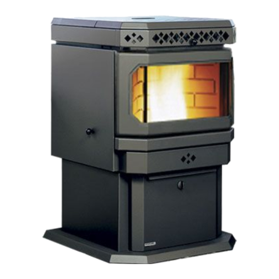
PELLET STOVE
VF100
H E A R T H P R O D U C T S
Freestanding, Fireplace Insert, and Built-In Heater
OWNER'S MANUAL
Contact your building or fire officials about restrictions and
installation inspection requirements in your area.
PLEASE READ THIS ENTIRE MANUAL BEFORE INSTALLATION AND USE
OF THIS PELLET BURNING ROOM HEATER. FAILURE TO FOLLOW THESE
INSTRUCTIONS COULD RESULT IN PROPERTY DAMAGE, BODILY INJURY,
OR EVEN DEATH.
VF-50279
Advertisement
Table of Contents

Subscribe to Our Youtube Channel
Related Manuals for Vistaflame VF100

Summary of Contents for Vistaflame VF100
- Page 1 SHERWOOD INDUSTRIES IS AN ENVIRONMENTALLY RESPONSIBLE COMPANY. THIS MANUAL IS PRINTED ON RECYCLED PAPER. PLEASE KEEP THESE INSTRUCTIONS FOR FUTURE REFERENCE PELLET STOVE VF100 H E A R T H P R O D U C T S Freestanding, Fireplace Insert, and Built-In Heater OWNER’S MANUAL...
-
Page 2: Table Of Contents
Table of Contents Introduction...........................3 Pellet Quality:........................3 Rating Label Location......................3 Important Safety Data......................4 Safety Warnings And Recommendations................4 Operating Instructions........................6 Automatic Safety Features....................6 Slider/Damper Setting......................6 Stove Controls........................7 Operating Your Pellet Stove....................8 Turning Your Pellet Stove Off....................8 Routine Cleaning and Maintenance....................9 Installation...........................12 Deciding Where to Locate your Pellet Appliance..............12 Removing Pellet Stove From Pallet..................12 Installation Of Pedestal - Insert...................13 Dimensions - Insert......................13... -
Page 3: Introduction
Introduction ELLET UALITY Pellet quality is important, please read the following: Your Vista Flame pellet stove has been designed to burn wood pellets only. Do not use any other type of fuel, as this will void any warranties stated in this manual. The performance of your pellet stove is greatly affected by the type and quality of wood pellets being burned. -
Page 4: Important Safety Data
Introduction MPORTANT AFETY Please read this entire Owner’s Manual before installing or operating your Vista Flame Pellet Stove. Failure to follow these instructions may result in property damage, bodily injury or even death. Contact your local building or fire official to obtain a permit and any information on installation restrictions and inspection requirements for your area. - Page 5 Vista Flame dealer. The VF100’s maximum power requirement is 520 watts. GLASS: Do not abuse the glass by striking or slamming the door. Do not attempt to operate the stove with broken glass.
-
Page 6: Operating Instructions
Operating Instructions UTOMATIC AFETY EATURES Your pellet Stove has the following safety features: A. The stove will shut off when the fire goes out and the exhaust temperature drops below 120°F (49°C). B. The stove has a high temperature safety switch. If the temperature on the hopper reaches 200°F (93°C), the auger will automatically stop and the stove will shut down when the exhaust temperature cools. -
Page 7: Stove Controls
Operating Instructions TOVE ONTROLS 1. AUGER TRIM: The Auger Trim Button is used to increase or decrease the feed rate on LOW, ONLY. Push the Auger Trim button until the number 1 and 5 lights appear on the Heat Level Indicator. This will increase the feed rate to 4 seconds ON time Auger pulse. -
Page 8: Operating Your Pellet Stove
Operating Instructions PERATING ELLET TOVE PRE-BURN INSTRUCTIONS: The burn pot liner holes must be clear and the liner installed properly against the ignitor tube for proper operation. Check the hopper for enough pellets to start the unit. DO NOT OPERATE THE UNIT WITH THE DOOR OR ASH PAN AJAR MANUAL MODE: TO START: Press the ON / OFF button. -
Page 9: Routine Cleaning And Maintenance
Routine Cleaning and Maintenance NOTE: Do not use abrasive cleaners to clean the surface or any part of the stove. The following should be inspected periodically to ensure that the appliance is operating at its optimum and giving you excellent heat value: TOOLS REQUIRED TO CLEAN UNIT •... - Page 10 FREESTANDING ASH PAN: The VF100 pellet stove freestanding’s ash pan is located under the burner, in the pedestal, and has a latching mechanism to secure it. To remove the ash pan, unlock the latch on the ash pan and then pull the pan out.
- Page 11 Routine Cleaning and Maintenance Installation of firebox backing: • Install the side panels in place. Insert center panel, hold the panels in place • Install the top rod by sliding it into one side panel then across into the other panel. Screw rod in place.
-
Page 12: Installation
Installation ECIDING HERE TO OCATE YOUR ELLET PPLIANCE 1. Check clearances to combustibles. 2. Do not obtain combustion air from an attic, garage or any unventilated space. Combustion air may be obtained from a ventilated crawlspace. 3. Do not install the stove in a bedroom. 4. -
Page 13: Installation Of Pedestal - Insert
Figure 8: Installing pedestal onto unit. IMENSIONS NSERT Regular Panel 40" (1016mm) Oversized Panel 46" (1158mm) 22" " (559mm) (601mm) " Regular Panel (322mm) " (766mm) Oversized Panel " (835mm) " " (579mm) (579mm) " (34mm) Figure 9: Dimensions of VF100 Insert. -
Page 14: Dimensions - Freestanding
(20.3 cm) Side facing to unit - 6 inches (15.2 cm) Floor protection - 6 inches (15.2 cm) on either side and to the front must be protected by non-combustible material. 6" (152mm) Figure 11: VF100 Fireplace Insert Clearance to Combustibles. -
Page 15: Clearances To Combustibles - Freestanding
6" (152 mm) ensure sufficient room for servicing, routine cleaning and maintenance. 6" (152 mm) Floor Protection Figure 12: VF100 Freestanding Clearance to Combustibles. LEARANCES TO LCOVE REESTANDING 36" (91cm) 30" Minimum Alcove width... -
Page 16: Vent Termination Requirements
Installation ERMINATION EQUIREMENTS IT IS RECOMMENDED THAT YOUR PELLET STOVE BE INSTALLED BY AN AUTHORIZED DEALER/INSTALLER. Table 1: Use in conjunction with Figure 14 for allowable exterior vent termination locations. Letter Minimum Clearance Description 24 in (61 cm) Above grass, top of plants, wood, or any other combustible materials. 48 in (122 cm) From beside/below any door or window that may be opened. -
Page 17: Outside Fresh-Air Connection
(372 mm ) 9" (228 mm) " (86 mm ) " " (132 mm ) 12" (132 mm ) 12" (304 mm) (304 mm) Figure 16: VF100 Freestanding Inlet and Outlet Figure 17: VF100 Fireplace Insert Inlet and Outlet Location. Location. -
Page 18: Mobile Home Installation - Freestanding
● Do not install in a room people sleep in. ● Outside fresh air is mandatory. Secure outside air connections directly to fresh air intake pipe and secure with three (3) screws evenly spaced. VF100 HEARTH PAD FLOORING STEEL FRAME GROUND WIRE DIRECTLY ”... -
Page 19: Horizontal Exhaust Through Wall Installation - Freestanding
Installation ORIZONTAL XHAUST HROUGH NSTALLATION REESTANDING Vent installation: install vent at clearances specified by the vent manufacturer. A chimney connector shall not pass through an attic or roof space, closet or similar concealed spaces, or a floor, or ceiling. Where passage through a wall or partition of combustible construction is desired, the installation shall conform to CAN/CSA-B365 Installation Code for Solid-Fuel-Burning Appliances and Equipment. -
Page 20: Through Wall With Vertical Rise And Horizontal Termination Installation - Freestanding
Installation 10. The pipe must extend at least 12” (30 cm) away from the building. If necessary, bring another length of pipe (PL type) to the outside of the home to connect to the first section. Do not forget to place high temperature silicone around the pipe that passes through the thimble. -
Page 21: Inside Vertical Installations - Freestanding
Installation NSIDE ERTICAL NSTALLATIONS REESTANDING 1. Choose a stove location that is ideal. See the section “D .” ECIDING HERE TO OCATE YOUR ELLET PPLIANCE 2. Place a non-combustible hearth pad where necessary. Rain cap 3. Place the unit on the hearth pad (if Flashing installed on a carpeted surface) and space the unit in a manner so when... -
Page 22: Hearth Mount Installation - Freestanding
Installation Rain cap Flashing 24" (61 cm) 3" (7.5 cm) Clearance 2" (5 cm) Support bracket Tee with cleanout 6" ���� ��� Type "L" ��������� ������ (15 cm) vent ����� ����� �� �������� Fresh air intake �������� �� ����� �� ���������... -
Page 23: Masonry Fireplace Installation - Fireplace Insert
Installation Rain cap Storm collar Seal plate (cover plate) Existing masonry flue Vent pipe (single wall stainless flex pipe or solid PL vent) Flexible vent connector (use this 5 foot [152cm] section of pipe to vent past fireplace damper or small shelf) Fireplace damper location Clean out tee... - Page 24 Installation Rain Cap Fresh-air intake Steel Plate or Flashing Flexible or Rigid 6" Stainless Steel Liner 4. Connect a tee or 90° degree elbow to the exhaust pipe. 5. This fireplace insert must installed with continuous chimney liner of 3” or 4”...
-
Page 25: Installation Into Factory Built Fireplaces
Installation NSTALLATION ACTORY UILT IREPLACES When installing the fireplace insert into a zero clearance fireplace, DO NOT cut or modify any factory firebox parts. If the fireplace insert does not fit into a zero clearance fireplace, we recommend you use a freestanding model and install as a hearth mounted unit. -
Page 26: Thermostat Installation
Installation HERMOSTAT NSTALLATION This control board can be placed into two different modes: When the jumper J9 is A) HI / LOW: When the jumper is placed not jumped then the control board is in a on only one of the J9 pins, HI / LOW mode operation. -
Page 27: Installation Of Control Panel Into Surround Panel - Insert
Installation NSTALLATION OF ONTROL ANEL INTO URROUND ANEL NSERT When installing the control panel into the surround panel, the surround does not need to be assembled. The control board will be found in behind the firebox. Place the control panel on the backside of the right surround panel so the hinge is on the outside and the top and bottom holes on the control panel line up with those on the surround. - Page 28 Installation 4. Using three (3) T-20 screws on each side attach the hinges on the side surround panels to the unit’s side panels (refer to Figure 37). 5. Plug the wiring harness into the control panel (see Figure 33). Figure 37: Panel placed on unit. 6.
-
Page 29: Troubleshooting
Troubleshooting DO NOT: ● Hold the ON / OFF BUTTON down for circuit board model or hold the start-up switch down for timer control. This is a momentary contact switch and can be damaged if held down too long. ● Service the stove with wet hands. The stove is an electrical appliance, which may pose a shock hazard if handled improperly. - Page 30 Troubleshooting « Check Vacuum levels in the exhaust channel by bypassing the Vacuum Switch, then remove the Vacuum hose from Vacuum Switch. Check exhaust vacuum readings by placing the open end of the Vacuum Hose on a Magnahelic Gauge (readings must be above 0.10” W.C. on low fire). Note: If the motor fails to reach a 0.10”...
- Page 31 Troubleshooting the hopper and remove the Auger Cover **Remember to re-seal the cover after installation** « Check the fuses on the circuit board (see “Troubleshooting - Fuses”). 7. Control settings (Heat Level) have no effect on the fire . ü If the system light is flashing, the Control Board has complete control of the unit. When the unit’s system light becomes solid, then control of the unit is given back to the operator.
-
Page 32: Fuses
Troubleshooting 11. Light # 2 on Heat output bar flashing. (The Vacuum Switch contacts have opened for more than 15 sec.) üPinch, break or blockage in Vacuum Hose - Check hose for pinch points or damage, replace or re-route as required. Blow out Vacuum Hose üBlocked Hose Barb on Exhaust Channel - Use a paper clip to clean out Hose Barb or remove the Vacuum Hose from the Vacuum Switch and blow into the hose to remove blockage. -
Page 33: Wiring Diagram
Wiring Diagram Grey Vacuum Grey Switch Blue Combustion Blower White Brown Power Cord F (49 Exhaust Temperature Sensor Brown Ground Black Black White White Black Common Thermostat 5 Amp Ignitor 5 V DC Fuses Black Black Black F (71 Convection White Blower Sensor... -
Page 34: Parts List
Parts List Reference Number Description Part Number Exhaust Temperature Sensor 120°F (60°C) EC-001 Power Cord - 115V EC-042 Auger Motor - 115V EF-001 Convection Blower - 115V EF-002 Convection Blower Impeller EF-004 Convection Blower Insulator (Gasket) EF-006 Combustion Main Impeller EF-008 Combustion Cooling Impeller EF-009... - Page 35 EF-194A Insert Hopper Lid With Knob, Stud, and Hinge EF-202 Pedestal & Ash Pan Gasket 10’ (3 m) EF-208 Insert Regular Panel with Black Trim VF100-001 Insert Oversized Panel with Black Trim VF100-002 Insert Pedestal VF100-003 Door Cover - Gold...
-
Page 36: Parts Diagram - Components
Parts Diagram - Components... -
Page 37: Parts Diagram - Steel
Parts Diagram - Steel... -
Page 38: Warranty
Warranty Sherwood Industries Ltd. gives a five year limited warranty on all steel manufactured parts. A one-year warranty is provided on all electrical components. The above limited warranties are extended only to the original purchaser. There is no warranty on the following parts: ●... -
Page 39: Installation Data Sheet
Installation Data Sheet The following information must be recorded by the installer for warranty purposes and future reference. NAME OF OWNER: NAME OF DEALER: _________________________________________ _________________________________________ ADDRESS: ADDRESS: _________________________________________ _________________________________________ _________________________________________ _________________________________________ _________________________________________ _________________________________________ PHONE:___________________________________ PHONE:___________________________________ MODEL:___________________________________ NAME OF INSTALLER: SERIAL NUMBER:___________________________ _________________________________________ DATE OF PURCHASE: _____________...
Need help?
Do you have a question about the VF100 and is the answer not in the manual?
Questions and answers