
Related Manuals for RynoWorx RA-MLT-0016

Summary of Contents for RynoWorx RA-MLT-0016
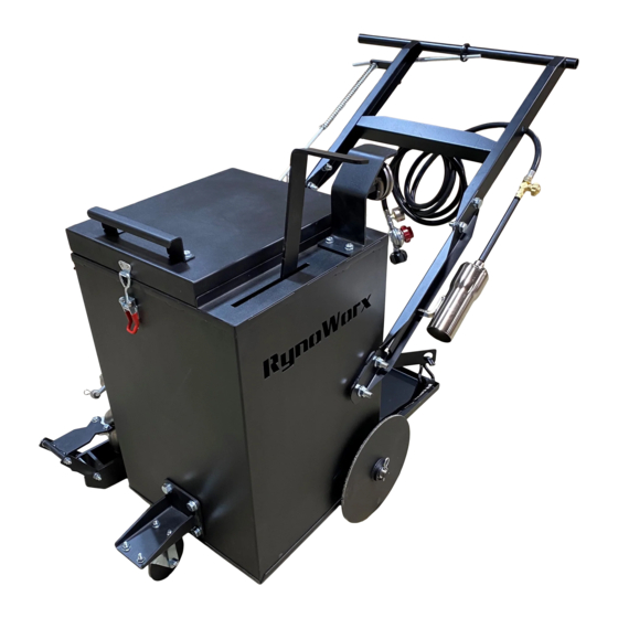
- Page 1 Operator's Manual Model: RY10MA-V3 with ErgoKit MPN: RA-MLT-0016 10 Gallon Direct Fire Melter Applicator Torch Model with Adjustable Handle Bars and On-the-Fly Agitation...
- Page 2 Facebook Messenger support@rynoworx.com WhatsApp Messaging 519-404-9775 Website Chat rynoworx.com/support Email support@rynoworx.com Phone 855-382-9611...
- Page 3 ⚠ Before servicing, make sure the unit is fully cooled and the liquid propane cylinder is disconnected. ⚠ Only genuine RynoWorx replacement parts should be used for any replacements or repairs. Do not attempt to modify or alter this product in any way.
- Page 4 16 RA-WHL-0026 2 Rear Wheel Assembly with Bearings - Melter Applicator - V2 1 Valve and Shoe Sub Asy 17 RA-BAS-0071 18 RA-WHL-0025 1 Front Caster Assembly P/N: Model Rev: RA-MLT-0016 RY10MA-V3 with ErgoKit Description: RY10MA - 10 Gallon Torch Fired Melter Applicator with ErgoKit - Complete Assembly - Version 3...
- Page 5 • Common Replacement Parts RA-WHL-0026 - Rear Wheel with Bearings RC-BRG-0001 - Wheel Bearing for Melter Applicator Rear Wheel RA-WHL-0005 - Front Caster with Wheel RC-STK-0001 - Flint Striker RC-WHL-0014 - 4 Bolt Caster Swivel RC-GCM-0016 - Torch for Melter Applicator with Valve RC-GCM-0067 - Thermometer - Shock Proof Glycerin Filled RC-GCM-0068 - Regulator and Hose with Pressure Gauge...
-
Page 6: Required Tools
Introduction Forward Thank you very much for purchasing RynoWorx crack maintenance equipment. We pride ourselves in being different from other equipment manufacturers with a relentless focus on innovation, simplicity, and quality. RY Series Melter / Applicators are designed to effectively melt and apply direct-fire type crack sealant to joints and cracks found in hard aggregate surfaces. - Page 7 1 Valve and Shoe Sub Asy RA-BAS-0071 1 Agitation Sweep Bar - MA-V4 RC-FAB-0143 5 RA-WHL-0026 2 Rear Wheel Assembly with Bearings - Melter Applicator - V2 P/N: Model Rev: RA-MLT-0016 RY10MA-V3 with ErgoKit Description: Parts Packed Inside the Kettle...
- Page 8 9 RC-GCM-0068 1 Regulator and Hose - 0 - 30 Psi with Pressure Gauge (3 m) 1 Flint Striker 10 RC-STK-0001 1 Propane Tank Ratchet Strap 11 RC-STR-0001 1 Tank Spacer - MA-V4 12 RC-FAB-0133 Fastener kit (RK-FAS-0086) also included. P/N: Model Rev: RA-MLT-0016 RY10MA-V3 with ErgoKit Description: Parts Packed Inside the component box...
- Page 9 • Assembly Instructions 1. Tank Shelf RK-FAS-0066 13 mm Wrench 2. Tank Spacer RK-FAS-0067 13 mm Wrench...
-
Page 10: Rear Wheels
3. Rear Wheels Assemble wheels on axle, the RK-FAS-0080 side with the bearing retainer ring should be facing out. Insert pin 4. Caster RK-FAS-0065 19 mm or ¾” Wrench... - Page 11 5. Valve and Shoe RK-FAS-0069 13 mm Wrench Valve should be aligned so it is perpendicular to the ground before the bolts are tightened ⚠ The lock washers provided for the valve are shipped in pairs. Use 1 pair for each bolt with the wedged surfaces on the washers mated together (same orientation that the washers come paired in).
- Page 12 6. Handle Bars Bend the handle bars over the mounting studs one side at a time RK-FAS-0083 19 mm or ¾” Wrench Tighten the handle bar nuts so that they are snug, nuts will be fully tightened in the set-up section.
- Page 13 7. Thermometer Thread the thermometer into the kettle 8. Thermometer Guard RK-FAS-0071 13 mm Wrench...
- Page 14 9. On-the-Fly Agitation Attach the agitation handle with the hardware preassembled on the handle bars 13 mm Wrench Remove the 2 bolts on the agitation connector handle and insert the handle into the slot and over the stud inside the kettle...
- Page 15 Remove the nuts threaded on the studs and install the agitation sweep bar as shown, put it over the left stud first and then the right Attach the agitation sweep bar by reassembling the bolts to the agitation connector handle 13 mm Wrench...
- Page 16 2 x RC-NUT-0023 Thread the provided nuts back on the stud and tighten just past flush with the end 19 mm or ¾” Wrench...
-
Page 17: Lid Handle
10. Lid Handle RK-FAS-0070 13 mm Wrench... - Page 18 11. Shoe Control Arm Insert the shoe control handle into the lower guide Insert the lower end of the shoe control rod into the shoe tab and insert the retaining pin.
- Page 19 12. Valve Control Arm Insert the valve control handle into the upper guide Turn the valve connector rod clockwise until it is tight and then turn it approximately 1 rotation counter- clockwise until its in the position shown on the left Insert the lower end of the control rod into the valve connector rod and insert...
- Page 20 Set Up – Handle Bars Adjust the handle bars to a comfortable height for the operator and tighten the flanged nuts on the studs (x2 each side)
- Page 21 Set Up – Control Rods ⚠ Every time the handle bar height is adjusted the control rods need to be adjusted to the appropriate length so that they function properly. Remove the spring retainer pin to put tension on the valve control rod Direction To Make Arm Longer Put a screwdriver through the hole in the turnbuckle to...
- Page 22 Adjust the length of the valve and shoe control rods so they are approximately in the position shown below. Valve control arm should be approximately 1/2” past the guide. Shoe control arm should be approximately 1” past the guide. Once the control rod lengths are set, use a screwdriver to hold the turnbuckle in place and tighten the nuts against the...
- Page 23 Set Up – Adjust Spring Tension The spring tension on the valve control arm can be adjusted by setting the pin position shown below which will increase or decrease the spring tension.
- Page 24 Set Up – Installing the Torch Connect the torch to the 30 psi adjustable regulator. Left-hand thread 19 mm wrench Insert the torch into the mounting bracket...
- Page 25 Set Up – Propane tank Place your propane tank on the shelf and secure with the ratchet strap. ⚠ Only tighten the ratchet strap so that it is snug, do not apply excess force on the brackets Connect the regulator to the propane tank...
- Page 26 • Operations Guide Before beginning please check the following: 1. You have read and understand all warnings on page 2. 2. You are using a new and full propane cylinder (use of a used cylinder can lead to reduced performance or equipment failure).
- Page 27 • Operation Guide Part 1 – How to Load and Light your Melter 1. Ensure your regulator is off by rotating regulator knob fully counter-clockwise (rotate left). 2. Slowly pressurize the regulator by rotating the valve located on the propane cylinder counter-clockwise all the way (rotate left).
- Page 28 • Operation Guide Part 2 – Agitating and Monitoring Temperature 1. Never leave melter unattended when the torch is lit. If flame goes out, promptly turn off the flow of gas; double check that the melter is free and clear of any gas odors before attempting to re-ignite the torch. 2.
- Page 29 • Maintenance Guide Periodic Maintenance This melter / applicator requires periodic maintenance before each use and at set intervals in order to ensure it is performing safely and optimally. The table below describes checks and maintenance which are recommended. Description Before Each Every 25 Every 75...
- Page 30 • Troubleshooting Guide Below we have provided a common problems and solutions table. Be sure to consult this table should you experience any technical problems. Description of Problem Possible Causes Known Solutions The torch will not ignite or 1) The fuel level could be too low 1) Check and refill your fuel tank the torch will not stay lit 2) The propane cylinder valve...
Need help?
Do you have a question about the RA-MLT-0016 and is the answer not in the manual?
Questions and answers