
Related Manuals for Xirgo XT4971A Series


Summary of Contents for Xirgo XT4971A Series
- Page 1 XT4971A Series User Guide Model: XT4971A FCC ID: GKM-XT4971A IC: 10281A-XT4971A Version 1.0...
-
Page 2: Table Of Contents
Table of Contents Document Change History ..................3 1 Introduction ......................4 1.1 Feature Matrix ....................................4 2 Hardware Description ....................5 2.1 Hardware Specifications ................................6 2.2 Cable Harness Description ................................. 6 2.3 LED Description ....................................7 3 Device Mounting Options ..................8 3.1 Screw Mounting .................................... -
Page 3: Document Change History
Document Change History Revision Date Author Changes 7/31/2017 Johnny Chen Document Creation based off XT4970D Series User Guide v1.1... -
Page 4: Introduction
1 Introduction The XT4971A is a solar energy harvesting cellular and GPS tracking device supporting long term, remote deployments without the need to replace the rechargeable battery. This user guide describes the physical hardware, associated parts, the different mounting options available, and a quick start-up procedure. -
Page 5: Hardware Description
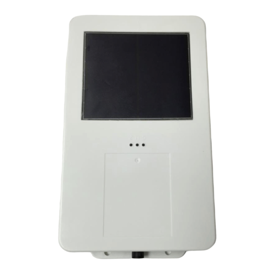
2 Hardware Description Below is a depiction of key interfaces of the XT4971A: Device/FCC Label Wake-up/ ZigBee Pairing Button Zigb Solar Panel LED Indicators 8-Pin Bayonet Connector The Associated Cable Harness that interfaces with the unit is shown below:... -
Page 6: Hardware Specifications
2.1 Hardware Specifications Cellular Technology Options ▪ 4G LTE bands: 2,4,5, and 12 ▪ 3G UMTS Band II and Band V GPS Specification ▪ Receiver channels 72 channels ▪ Receiver tracking Sensitivity -167 dBm ▪ Accuracy +/- 2.0 m CEP (50% , -130 dBm, > 6 Satellites) ▪... -
Page 7: Led Description
Pin # Wire Color Pin Name Functional Description Port Characteristic Blue VBATT Ignition Sense 8v to 24v, Internally pulled low Ground 2.4 to 24V, < 0.2 V Brown Note: Internally pulled high Yellow Black ADC2 8-24 V RS232 RX RS232 Receive Port 3V Logic Interface Com Port Settings: White... -
Page 8: Device Mounting Options
3 Device Mounting Options 3.1 Screw Mounting The XT4971A has two flanges (two holes per) at each end of the housing for screw mounting the device to the mounting surface. 3.2 3M VHB Tape Mounting For a semi-permanent option, the device can be mounted with 3M VHB tape as shown below:... -
Page 9: Trailer Cradle Mounting
3.3 Trailer Cradle Mounting An optional trailer mounting cradle can be purchased for easy device mounting for the XT4971A. The cradle will need to be screw-mounted or VHB Tape mounted to the position desired. The XT4971A can be easily fastened into the cradle via a Phillips head screw. The angled edged of the cradle is designed to withstand the impact of snow scrapers that may come in contact to the cradle if mounted on the top of a typical trailer. -
Page 10: Device Mounting Guidelines
3.5 Device Mounting Guidelines The XT4971A Series devices leverage solar energy to replenish the charge of its battery. Please consider the device mounting guidelines to maximize device solar charging. Also, the XT4971A series uses cellular and GPS technologies whose signal reception quality is depending on mounting location and style. -
Page 11: Quick Start Guide
4 Quick Start Guide 4.1 Device Wakeup To start up the device, simply hold the black button located near the circular connector on the side panel of the device for 3 seconds. You should see the blue “C” LED light up and then fade out. The blue LED will blink when the device is successfully connected to the network. -
Page 12: Configuring The Device Via Sms
4.2 Configuring the Device via SMS 1) Ensure your device is active on your cellular account. 2) Awaken device from sleep XT4971A via the “wake-up” button. 3) If the device needs more power, then supply 12V DC via the red wire of the cable harness. 4) Ensure device cellular LED is blinking based on LED definition in this document. -
Page 13: Download Over The Air (Dota) Firmware Update Guide
6) You can now configure the device by sending the XT commands listed in the protocol document of this device. a. Command +XT:1010 configures network settings b. Command +XT:3017 configures the sleep/wake mode for the device. i. The factory defaults for this device is to operate in the sleep timer mode and have a minute of wake time max. - Page 14 FCC/IC: REGULATORY COMPLIANCE INFORMATION This equipment with FCC-ID: GKM-XT4971A and IC-ID: 10281A-XT4971A, HVIN: XT4971A is subject to the Federal Communications Commission (FCC) and Industry Canada (IC) rules. Changes or modifications not expressly approved by the party responsible for compliance could void the user's authority to operate the equipment.
Need help?
Do you have a question about the XT4971A Series and is the answer not in the manual?
Questions and answers