Table of Contents
Advertisement
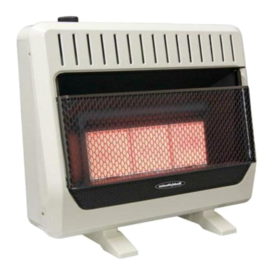
VENT-FREE GAS WALL
HEATER
OWNER'S OPERATION AND
INSTALLATION MANUAL
INFRARED MODELS
IWH16NLTD-2
IWH26NLTD-2
WARNING: If the information in this manual is not
followed exactly, a fire or explosion may result causing
property damage, personal injury or loss of life.
— Do not store or use gasoline or other flammable va-
pors and liquids in the vicinity of this or any other
appliance.
— WHAT TO DO IF YOU SMELL GAS
• Do not try to light any appliance.
• Do not touch any electrical switch; do not use any
phone in your building.
• Immediately call your gas supplier from a neighbor's
phone. Follow the gas supplier's instructions.
• If you cannot reach your gas supplier, call the fire
department.
— Installation and service must be performed by a quali-
fied installer, service agency or the gas supplier.
WARNING: This appliance is equipped for Natural and
Propane gas. Field conversion is not permitted other than
between natural or propane gases.
Before returning to your retailer, call our customer service department at
DRAFT
4-10-17
Questions, problems, missing parts?
1-800-229-5647, 8:00 am - 4:30 pm EST, Monday through Friday
IWH26NLTD-2
Shown
Advertisement
Table of Contents

Related Manuals for ReddyHeater IWH16NLTD-2


Summary of Contents for ReddyHeater IWH16NLTD-2
- Page 1 VENT-FREE GAS WALL HEATER OWNER’S OPERATION AND INSTALLATION MANUAL INFRARED MODELS IWH16NLTD-2 IWH26NLTD-2 DRAFT 4-10-17 IWH26NLTD-2 Shown WARNING: If the information in this manual is not followed exactly, a fire or explosion may result causing property damage, personal injury or loss of life.
-
Page 2: Table Of Contents
TABLE OF CONTENTS Safety ............3 Operation ..........18 Qualified Installing Agency ......4 Electrical Connection ....... 20 Product Features ........4 Electrical Wiring ........20 Specifications ..........5 Inspecting Burners........21 Local Codes..........5 Care And Maintenance ......22 Preparing For Installation ...... -
Page 3: Safety
SAFETY NATURAL AND PROPANE/LP GAS: Natural IMPORTANT: Read this owner’s and Propane/LP gas are odorless. An odor- manual carefully and completely making agent is added to the gas. The odor before trying to assemble, op- helps you detect a gas leak. However, the erate, or service this heater. -
Page 4: Qualified Installing Agency
SAFETY 1. Do not place Propane/LP supply tank(s) 6. Do not run heater: inside any structure. Propane/LP supply • Where flammable liquids or vapors are tank(s) must be placed outdoors. used or stored. 2. Heaters with a maximum input over •... -
Page 5: Specifications
SPECIFICATIONS Model IWH16NLTD-2 IWH26NLTD-2 Ignition Gas Type Natural Propane Natural Propane BTU/Hr Input Max. (available) 20,000 18,000 30,000 28,000 Pressure Regulator Setting 6" W.C. 10" W.C. 6" W.C. 10" W.C. Max. 9.5" Max. 14" Max. 9.5" Max. 14" Inlet Gas Pressure* (inches of water) Min. -
Page 6: Preparing For Installation
Grill Heater Cabinet Front Panel Figure 1 - Vent-Free Gas Heater IWH16NLTD-2 Shown with Base Feet UNPACKING 1. Remove heater from carton. 3. Check heater for any shipping damage. If heater is damaged, promptly inform dealer 2. Remove all protective packaging applied where you bought heater. -
Page 7: Air For Combustion And Ventilation
AIR FOR COMBUSTION AND VENTILATION WARNING: This heater shall WARNING: This heater shall not be installed in a room or not be installed in a confined space space unless the required vol- or unusually tight construction ume of indoor combustion air unless provisions are provided for adequate combustion and is provided by the method de-... - Page 8 AIR FOR COMBUSTION AND VENTILATION VENTILATION AIR Ventilation Air From Inside Building Ventilation Air From Outdoors Provide extra fresh air by using ventilation This fresh air would come from an adjoining grills or ducts. You must provide two perma- unconfined space. When ventilating to an nent openings: one within 12"...
-
Page 9: Installation
INSTALLATION IMPORTANT: Vent-free heaters add moisture NOTICE: This heater is intended to the air. Although this is beneficial, installing for use as supplemental heat. heater in rooms without enough ventilation air Use this heater along with your may cause mildew to form too much moisture. primary heating system. - Page 10 INSTALLATION REMOVING FRONT PANEL 1. Remove 4 screws securing front panel. 2. Carefully slide front panel forward. Screw Front Panel Figure 5 - Removing Front Panel INSTALLING THERMOSTAT SENSING BULB (OPTIONAL) (For Heaters with Blower Installed Only) 1. Carefully remove bulb clips with ther- 4.
- Page 11 (see Figure 9). Hole On Each End IMPORTANT: Do not hammer anchor key! For thick walls (over 1/2" thick) or solid walls, do IWH16NLTD-2 not pop open wings. Non-combustible Flooring or Top of 5. Place mounting bracket onto wall. Line up...
- Page 12 INSTALLATION Placing Heater On Mounting Bracket 1. Locate two horizontal slots on back panel of heater (see Figure 10). 2. Place heater onto mounting bracket. Slide Front View horizontal slots onto stand-out tabs on mounting bracket. Front View Horizontal Slots Wall Heater Stand-...
- Page 13 INSTALLATION GAS SELECTION This appliance is factory INLET GAS PRESSURE preset for propane/LP gas. MAX 1/2 PSIG (3.5 KPA) No changes are required for connecting to propane/LP. Only a qualified installer or service technician can perform gas selec- tion and connecting to gas supply. Gas Connection CAUTION: Two gas line in- Figure 14 - Bottom of Heater...
- Page 14 INSTALLATION 2. Apply thread sealant to the threads on a Use only the cap supplied on the 3/8" NPT brass connection fitting. While regulator. Do not use an off the pushing in, rotate the fitting clockwise until shelf pipe plug. This can damage the threads engage the regulator.
- Page 15 INSTALLATION CONNECTING TO GAS SUPPLY WARNING: A qualified ser- CAUTION: For propane/LP gas, Never connect heater directly vice technician must connect to the gas supply. This heater heater to gas supply. Follow all requires an external regulator local codes. (not supplied). Install the external WARNING: This appliance regulator between the heater and requires a 3/8"...
- Page 16 INSTALLATION Apply pipe joint sealant lightly to male threads. as shown in Figure 17. Pointing the vent down This will prevent excess sealant from going protects it from freezing rain or sleet. into pipe. Excess sealant in pipe could result Install sediment trap in supply line as shown in clogged heater valves.
- Page 17 INSTALLATION Test Pressures Equal To or Less Than 1/2 PSIG (3.5 kPa) Gas Valve 1. Close equipment shutoff valve (see Fig- ure 18). Propane/LP 2. Pressurize supply piping system by either Supply Tank using compressed air or opening gas sup- ply valve.
-
Page 18: Operation
OPERATION FOR YOUR SAFETY READ BEFORE LIGHTING • Immediately call your gas supplier WARNING: If you do not fol- from a neighbor’s phone. Follow the low these instructions exactly, a gas supplier’s instructions. fire or explosion may result caus- • If you cannot reach your gas supplier, call the fire department. - Page 19 NG, make sure NG pilot burner level between 1 and 5. ignites. If input gas type is LP, Natural make sure LP pilot burner ignites. Thermocouple Ignitor Burner Electrode IWH16NLTD-2 IWH26NLTD-2 Propane/LP Gas Burner Burners on HIGH Pilot Air Inlet Hole Pilot Air Burners OFF...
-
Page 20: Electrical Connection
ELECTRICAL CONNECTION FOR BLOWER KIT Do not use this heater if any part of it has been under water. Immediately call a qualified ser- Cover of vice technician to inspect the Grounded Grounding Pin heater and replace any part of Outlet Box the electrical system which has been under water. -
Page 21: Inspecting Burners
INSPECTING BURNERS IMPORTANT: Owner’s should check pilot flame pattern and burner flame pattern often. Incorrect flame patterns indicate the need for cleaning (see Care and Maintenance, page 22) or service. WARNING: Only a qualified service person should service and repair heater. This includes maintenance requiring replacement or alteration of components. -
Page 22: Care And Maintenance
CARE AND MAINTENANCE WARNING: Turn off heater and let cool before servicing. CAUTION: You must keep control areas, burner, and circulating air passageways of heater clean. Inspect these areas of heater before each use. Have heater inspected yearly by a qualified service techni- cian. -
Page 23: Troubleshooting
CARE AND MAINTENANCE MAINTENANCE OF BLOWER MOTOR (IF EQUIPPED) Always disconnect the appliance from the heavy or continuous use, periodic cleaning main power supply and allow it to cool must be done more frequently. If the heater before any servicing operation. blows alternating cold and warm air, check the fan for free movement and for debris restrict- The motors used on the fan heater and flame... - Page 24 TROUBLESHOOTING Only a qualified installer should bypass the pressure switch. Remove front panel of heater (see page 10). Locate the gas regulator. To by- pass the pressure switch locate the set screw on the regulator. Use a small flat bladed screw driver to turn the set screw counterclockwise 2 turns.
- Page 25 TROUBLESHOOTING Problem Possible Cause Corrective Action ODS/pilot lights but flame 1. Control knob is not fully 1. Press in control knob fully. goes out when control pressed in. knob is released. 2. Control knob is not pressed 2. After ODS/pilot lights, keep in long enough.
-
Page 26: Technical Service
TROUBLESHOOTING Problem Possible Cause Corrective Action Heater produces a whis- 1. Turning control knob to high 1. Turn control knob to low (1) tling noise when burner (5) position when burner is position and let warm up for is lit. cold. -
Page 27: Replacement Parts
REPLACEMENT PARTS Note: Use only original replacement parts. This will protect your warranty coverage for parts replaced under warranty. PARTS UNDER WARRANTY PARTS NOT UNDER WARRANTY C a l l C u s t o m e r S e r v i c e t o l l f r e e a t C a l l C u s t o m e r S e r v i c e t o l l f r e e a t 1-800-229-5647 to order parts under war- 1-800-229-5647 to order parts not under... - Page 28 PARTS MODELS IWH16NLTD-2 AND IWH26NLTD-2 IWH26NLTD-2 Shown www.sureheat.com 200319-01C...
- Page 29 PARTS MODELS IWH16NLTD-2 AND IWH26NLTD-2 This list contains replaceable parts for your heater. When ordering replacement parts, follow the instructions listed under Replacement Parts on page 27 of this manual. ITEM IWH16NLTD-2 IWH26NLTD-2 DESCRIPTION Back Body Panel 161132-01 161562-01 Mounting Bracket...
- Page 30 NOTES ________________________________________________________________ ________________________________________________________________ ________________________________________________________________ ________________________________________________________________ ________________________________________________________________ ________________________________________________________________ ________________________________________________________________ ________________________________________________________________ ________________________________________________________________ ________________________________________________________________ ________________________________________________________________ ________________________________________________________________ ________________________________________________________________ ________________________________________________________________ ________________________________________________________________ ________________________________________________________________ ________________________________________________________________ ________________________________________________________________ ________________________________________________________________ ________________________________________________________________ ________________________________________________________________ ________________________________________________________________ ________________________________________________________________ ________________________________________________________________ ________________________________________________________________ www.sureheat.com 200319-01C...
- Page 31 NOTES ________________________________________________________________ ________________________________________________________________ ________________________________________________________________ ________________________________________________________________ ________________________________________________________________ ________________________________________________________________ ________________________________________________________________ ________________________________________________________________ ________________________________________________________________ ________________________________________________________________ ________________________________________________________________ ________________________________________________________________ ________________________________________________________________ ________________________________________________________________ ________________________________________________________________ ________________________________________________________________ ________________________________________________________________ ________________________________________________________________ ________________________________________________________________ ________________________________________________________________ ________________________________________________________________ ________________________________________________________________ ________________________________________________________________ ________________________________________________________________ ________________________________________________________________ www.sureheat.com 200319-01C...
-
Page 32: Warranty
WARRANTY KEEP THIS WARRANTY Model _______________________________ Serial No. ____________________________ Date Purchased _______________________ Keep receipt for warranty verification. IMPORTANT: We urge you to fill out your warranty information above. Complete with the entire serial number which can be found on the rating plate. Retain this manual for future reference. Always specify model and serial numbers when communicating with customer service.
Need help?
Do you have a question about the IWH16NLTD-2 and is the answer not in the manual?
Questions and answers
How to remove the grill?
To remove the grill on a ReddyHeater IWH16NLTD-2, you need to:
1. Remove the four screws securing the front panel.
2. Carefully slide the front panel (grill) forward.
This answer is automatically generated