Table of Contents
Advertisement
Quick Links
Advertisement
Table of Contents
Troubleshooting

Subscribe to Our Youtube Channel
Related Manuals for Microsemi PD96 Series


Summary of Contents for Microsemi PD96 Series
- Page 1 Microsemi PD96XX Series PD-9606G & PD-9612G PD-RPS-1000 User Guide...
- Page 2 Microsemi reserves the right to make changes to products and to their specifications as described in this document, at any time, without prior notice. Do not photocopy or reproduce this material without permission.
-
Page 3: Table Of Contents
NSTALLATION 4.1 Background Information ..............15 4.2 Verifying Kit Contents ................15 4.3 Rack Mounting Brackets ..............16 4.4 Installation Factors ................16 © Microsemi Corp. Microsemi Page 3 CPG – Poe BU Rev.B01 One Enterprise Aliso Viejo, CA 92656 USA... - Page 4 8.1 Power Redundancy ................26 8.2 Power Backup ..................26 8.3 Connectors................... 27 8.4 Connecting Backup and Redundancy Connectors ....... 28 8.5 Power Backup and Power Redundancy Indications ......30 © Microsemi Corp. Microsemi Page 4 CPG – Poe BU Rev.B01...
-
Page 5: Front Material
PD-RPS-AAAA: Redundant Power Supply, where AAAA represents available power in Watts. Electrical Compatibility Approvals Microsemi 96xxG series complies with the following standards: FCC Part 15; class UTP cabling EN 55022 (CISPR 22); class B with UTP cabling ... -
Page 6: Safety Information
Do not stack more than four Power over Ethernet Midspan units. When disposing this product, follow all local laws and regulations. © Microsemi Corp. Microsemi Page 6 CPG – Poe BU Rev.B01 One Enterprise Aliso Viejo, CA 92656 USA... -
Page 7: Power Cord
13A for PD-9612G/ACDC/M, PD- 9606G/ACDC/M; Attachment plug must be an earth-grounding type with a NEMA 5-15P (15A, 125V) or NEMA 6-15P (15A, 250V) configuration. © Microsemi Corp. Microsemi Page 7 CPG – Poe BU Rev.B01 One Enterprise Aliso Viejo, CA 92656 USA... - Page 8 Neutral and connected directly to ground. Power over Ethernet Midspan is covered by General Approval NS/G/12345/J/100003, for indirect connection to a public telecommunications system. © Microsemi Corp. Microsemi Page 8 CPG – Poe BU Rev.B01 One Enterprise Aliso Viejo, CA 92656 USA...
-
Page 9: About The Power Over Ethernet Midspan
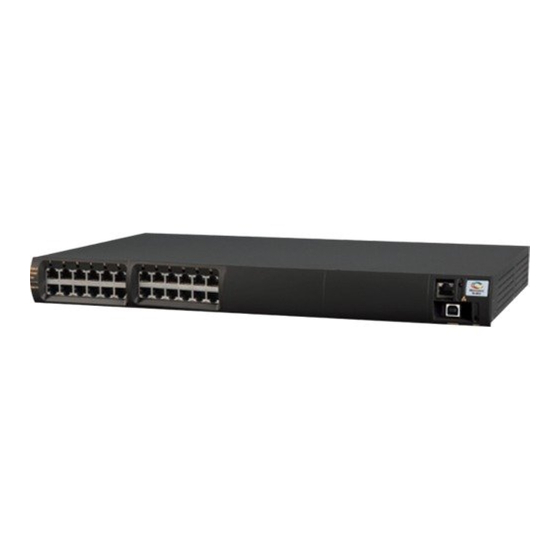
3 About the Power over Ethernet Midspan Microsemi’s family of Power over Ethernet Midspans 96xx inject power over data-carrying Ethernet cabling. Employing these devices reduces the need for AC outlets, local UPS and AC/DC adapters near PDs. PD-9606G/9612G Midspans support 6 and 12 ports respectively, in a 10/100/1000BaseTx Ethernet network, over TIA/EIA-568 category 5/5e/6 cabling. -
Page 10: 10/100/1000Base-Tx Ports Definition
2-wire pairs (pins 1/2 and 3/6) (10/100Base-T) PD-96xxG series carry DC power over 4-wire pairs (pins 4/5, 7/8 and pins 1/2, 3/6) © Microsemi Corp. Microsemi Page 10 CPG – Poe BU Rev.B01 One Enterprise Aliso Viejo, CA 92656 USA... -
Page 11: Indicators
4-wire pairs. Yellow indicates terminal unit (PD) has been identified as "Power over Ethernet Enabled"; it is active and receiving power over 2-wire pairs. © Microsemi Corp. Microsemi Page 11 CPG – Poe BU Rev.B01 One Enterprise Aliso Viejo, CA 92656 USA... - Page 12 (only if Maintenance measures voltage range) power should be taken backup is whenever possible. connected) © Microsemi Corp. Microsemi Page 12 CPG – Poe BU Rev.B01 One Enterprise Aliso Viejo, CA 92656 USA...
-
Page 13: Connectors
Console port is set to 38,400-baud for managed units and 19,200-baud for unmanaged units, 8 data bits, no parity, and 1 stop bit. Figure 3 -2 displays pin connections for this connector. © Microsemi Corp. Microsemi Page 13 CPG – Poe BU Rev.B01... - Page 14 Each data port is configured, as shown in Figure Through” ports for all data pins (pins 1, 2, 3, 6, 4, 5, 7, and 8). Make sure you are using cabling of Category 5 or higher. © Microsemi Corp. Microsemi Page 14 CPG –...
-
Page 15: Power Over Ethernet Midspan Installation
Power over Ethernet Midspan Mounting brackets (for 19-inch racks) and a plastic cover Screws for assembling mounting brackets Self-adhesive rubber feet © Microsemi Corp. Microsemi Page 15 CPG – Poe BU Rev.B01 One Enterprise Aliso Viejo, CA 92656 USA... -
Page 16: Rack Mounting Brackets
Elevated Operating Ambient Temperature: If installed in a closed or multi-unit rack assembly, operating ambient temperature in rack environment may be greater than room ambient temperature. Therefore, install © Microsemi Corp. Microsemi Page 16 CPG – Poe BU Rev.B01... -
Page 17: Connecting Ethernet Cables
DATA & POWER OUT ports (upper row on front panel). 4.6 Connecting Power Cables When using an AC source to power Midspan, plug in the provided power cord to back AC connector. © Microsemi Corp. Microsemi Page 17 CPG – Poe BU Rev.B01... -
Page 18: Powering Up The Unit
Power indicator remains lit in green; port indicators are off. Ports are now ready (enabled) for normal operation. If LEDs are not lit, refer to Troubleshooting on page 19. © Microsemi Corp. Microsemi Page 18 CPG – Poe BU Rev.B01... -
Page 19: Troubleshooting
Ethernet cable from network is connected to DATA port. Ethernet cable to PD is connected to DATA & POWER port. Cable pairs are attached to their corresponding ports. © Microsemi Corp. Microsemi Page 19 CPG – Poe BU Rev.B01 One Enterprise Aliso Viejo, CA 92656 USA... -
Page 20: Troubleshooting Steps
Midspan or on another one. If it works, there is probably a faulty output port or RJ-45 connection. 7. Verify port shutdown command was not issued via Web management. © Microsemi Corp. Microsemi Page 20 CPG – Poe BU Rev.B01... - Page 21 4. Try to reconnect the same PD to a different port on the same Midspan or on another one. If it works, there is probably a faulty port or faulty RJ-45 connection. © Microsemi Corp. Microsemi Page 21 CPG – Poe BU Rev.B01...
-
Page 22: Specifications
6.2 Environmental Specifications Operating Temperature 0° to +40°C (32° to 104°F) Storage Temperature -20 to +70°C (-4° to 158°F) Humidity 10 to 90% (non-condensing) © Microsemi Corp. Microsemi Page 22 CPG – Poe BU Rev.B01 One Enterprise Aliso Viejo, CA 92656 USA... -
Page 23: Electrical Specifications
Maximum Output Power per PD-96XX series 95W Port PD-9612G/ACDC/M, PD-9606G/ACDC/M & Parameter PD-RPS-1000 DC Input Rated 53-57 Voltage Input DC Maximum Current © Microsemi Corp. Microsemi Page 23 CPG – Poe BU Rev.B01 One Enterprise Aliso Viejo, CA 92656 USA... -
Page 24: Microsemi's Powerview Pro
7 Microsemi’s PowerView Pro Microsemi’s PowerView Pro is a secure remote management system offering real time monitoring and control, with graphical representation, status indicators, and alarms. PowerView Pro manages Midspans via an Internet browser interface or via a Network Management System (NMS). - Page 25 Multi-manager capabilities Event and performance data recording Runs on a PC platform with Windows graphic user interface (GUI) © Microsemi Corp. Microsemi Page 25 CPG – Poe BU Rev.B01 One Enterprise Aliso Viejo, CA 92656 USA...
-
Page 26: Power Backup And Power Redundancy Connection
Power Backup 8.1 Power Redundancy Microsemi 's power redundancy mode is available in 96xxG Midspan series. This mode enables internal power supply backup for two Midspans connected to each other. This mode provides seamless failover between two Midspans. If one of the two Midspans' internal power supplies fails, failure is detected automatically and working power supply provides power to Midspan. -
Page 27: Connectors
Power Backup & Current Terminal Block Sharing Control Signal Earth Ground Connection Connector Connection Figure 8 -1: PD-96xxG Rear Panel Connectors © Microsemi Corp. Microsemi Page 27 CPG – Poe BU Rev.B01 One Enterprise Aliso Viejo, CA 92656 USA... -
Page 28: Connecting Backup And Redundancy Connectors
6. Verify Power Indicator LED is ON (Green LED). Note: When connecting a midspan to midspan or to an RPS unit - Connect the earth ground cable between both units Earth Ground connection. © Microsemi Corp. Microsemi Page 28 CPG – Poe BU Rev.B01... - Page 29 If Power Indicator LED is not lit, refer to Troubleshooting on page 19. Note: RPS functionality can be monitored via NMS as described in Section 8 .3. © Microsemi Corp. Microsemi Page 29 CPG – Poe BU Rev.B01 One Enterprise Aliso Viejo, CA 92656 USA...
-
Page 30: Power Backup And Power Redundancy Indications
Redundancy, NMS View-Status window displays 'Power Source Status' field. 'Power Source Status' field shows both internal and external power supply statuses (green indication for 'OK and red indication for 'Fail'). © Microsemi Corp. Microsemi Page 30 CPG – Poe BU Rev.B01... - Page 31 Indicator LED; whenever unit's internal power supply fails, Power Indicator LED blinks once every second (Green LED). Unit Main LED Figure 8 -4: PD-96xxG Front Panel LED Indication © Microsemi Corp. Microsemi Page 31 CPG – Poe BU Rev.B01...
- Page 32 CONFIDENTIAL information of Microsemi and cannot be copied, published, uploaded, posted, transmitted, distributed or disclosed or used without the express duly signed written consent of Microsemi If the recipient of this document has entered into a disclosure agreement with Microsemi, then the terms of such Agreement will also apply .
- Page 33 Mouser Electronics Authorized Distributor Click to View Pricing, Inventory, Delivery & Lifecycle Information: Microchip PD-9606GC/AC PD-9606GC/AC-AU PD-9606GC/AC-EU PD-9606GC/AC-JP PD-9606GC/AC-UK PD-9606GC/AC- US PD-9612GC/AC PD-9612GC/AC-AU PD-9612GC/AC-EU PD-9612GC/AC-JP PD-9612GC/AC-UK PD- 9612GC/AC-US...
Need help?
Do you have a question about the PD96 Series and is the answer not in the manual?
Questions and answers