Advertisement
Quick Links
Advertisement

Subscribe to Our Youtube Channel
Related Manuals for PCB Piezotronics IMI SENSORS 682C05


Summary of Contents for PCB Piezotronics IMI SENSORS 682C05
- Page 1 Model 682C05 BEARING FAULT DETECTOR Installation and Operating Manual For assistance with the operation of this product, contact the PCB Piezotronics, Inc. Toll-free: 800-959-4464 24-hour SensorLine: 716-684-0001 Fax: 716-684-3823 E-mail: imi@pcb.com Web: www.imi-sensors.com...
- Page 2 Assistance is needed to safely operate equipment PCB Piezotronics is an ISO-9001 certified company whose Damage is visible or suspected calibration services are accredited by A2LA to ISO/IEC Equipment fails or malfunctions 17025, with full traceability to SI through N.I.S.T.
- Page 3 CAUTION Refers to hazards that could damage the instrument. NOTE Indicates tips, recommendations and important information. The notes simplify processes and contain additional information on particular operating steps. The following symbols may be found on the equipment described in this manual: This symbol on the unit indicates that high voltage may be present.
- Page 4 PCB工业监视和测量设备 - 中国RoHS2公布表 PCB Industrial Monitoring and Measuring Equipment - China RoHS 2 Disclosure Table 有害物质 镉 汞 铅 (Pb) 六价铬 (Cr(VI)) 多溴联苯 (PBB) 多溴二苯醚 (PBDE) 部件名称 (Hg) (Cd) 住房 PCB板 电气连接器 压电晶体 环氧 铁氟龙 电子 厚膜基板 电线 电缆 塑料 焊接...
- Page 5 Component Name Hazardous Substances Lead (Pb) Mercury (Hg) Cadmium (Cd) Chromium VI Polybrominated Polybrominated Compounds Biphenyls (PBB) Diphenyl Ethers (Cr(VI)) (PBDE) Housing PCB Board Electrical Connectors Piezoelectric Crystals Epoxy Teflon Electronics Thick Film Substrate Wires Cables Plastic Solder Copper Alloy/Brass This table is prepared in accordance with the provisions of SJ/T 11364.
- Page 6 Model 682C05 Bearing Fault Detector Operating Guide with Enclosed Warranty Information 3425 Walden Avenue, Depew, New York 14043-2495 Phone (716) 684-0003 Fax (716) 684-3823 Toll Free Line 1-800-959-4IMI MANUAL NUMBER: 53377 MANUAL REVISION: ECN NUMBER: 50130...
-
Page 7: Table Of Contents
Table of Contents Introduction ........................Page 3 General Features Installation and Wiring ..................... Page 4 Configuring the 682C05 ....................Page 8 ESD Sensitivity ....................... Page 10 Warranty/Servicing Warranty, Service & Return Procedure ................Page 11 Customer Service ......................Page 12 PAGE 2... -
Page 8: Introduction
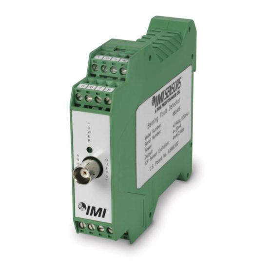
Introduction The Model 682C05 is a 4-20mA Din Rail Signal Conditioner designed to interface with IMI Sensor’s ICP ® accelerometer for bearing fault detection. Specifically, the 682C05 detects high frequency impacts related to bearing fault/lube starvation and provides a 4-20mA signal proportional to the magnitude of vibration. From the same sensor, the device also converts overall vibration to a 4-20mA signal, which is used for traditional machine diagnostics and predictive maintenance such as out of balance and misalignment. -
Page 9: Installation And Wiring
Installation and Wiring Installation The Model 682C05 is designed to be mounted on a 35mm Din Rail. Do not install in a harsh area where it can be exposed to cleaning fluids or machine oils. IMI Sensors recommends mounting the 682C05 in a type NEMA 4 enclosure similar to the Model 682A00 to protect the electronics from contamination. - Page 10 Connector and Pinout Diagram The 682C05 uses plug-in type screw terminal connectors for all input and output connections. Strip off 8mm of insulation from the connection wire ends. Using a screwdriver, remove the terminal block from the enclosure in either the up or down direction, terminate the wire in the correct location. Do not exceed a torque of 0.5Nm.
- Page 11 Pin Descriptions: DC Power – Pins 1 through 4: Pin 1 +Power Pin 2 -Power/Common Pin 3 Earth Ground Pin 4 No Connection Accelerometer – Pins 5 through 8: ® ® Pin 5 + ICP Accelerometer ® Pin 6 - ICP Accelerometer Pin 7 Shield...
- Page 12 Typical Wiring Diagram Note: If using the 682A01, mount the 682C05 to the left side of the power supply (as shown) with a recommended minimum separation distance of 4” where applicable. PAGE 7...
-
Page 13: Configuring The 682C05
Configuring the 682C05 POWER OUTPUT1 LED1 S456 PT.NO. 50831-01 Internal PC Board Diagram The Internal PC Board Diagram shows the location of the internal DIP and Slide switches. The switches are used to configure the 682C05 for various sensor and vibration ranges. The PC Board is accessible through the front of the conditioner by removing the Screw Terminal Connectors and disengaging the tabs on the TOP and BOTTOM of the enclosure with a screwdriver. - Page 14 Internal Switch Settings ® The internal switches of the Model 682C05 must be configured for the Full Scale Output of the ICP Sensor connected to it. This is accomplished by removing the front cover and sliding the PC Board out of the Signal Conditioner.
-
Page 15: Esd Sensitivity
Warning 2 – ESD sensitivity This equipment is designed with user safety in mind; however, the protection provided by the equipment may be impaired if the equipment is used in a manner not specified by PCB Piezotronics, Inc. Caution 1 – ESD sensitivity Cables can kill your equipment. -
Page 16: Warranty, Service & Return Procedure
therefore be done ONLY at an ESD-safe work area. Many products have ESD protection, but the level of protection may be exceeded by extremely high voltage. Warranty IMI instrumentation is warranted against defective material and workmanship for 1 year unless otherwise expressly specified. -
Page 17: Customer Service
Customer Service IMI, a division of PCB Piezotronics, guarantees Total Customer Satisfaction. If, at any time, for any reason, you are not completely satisfied with any IMI product, IMI will repair, replace, or exchange it at no charge. You may also choose, within the warranty period, to have your purchase price refunded. - Page 18 Model Number Revision: NR BEARING FAULT DETECTOR ECN #: 46949 682C05 Performance ENGLISH OPTIONAL VERSIONS Input Signal 100 mV/g 10.2 mV/(m/s²) Optional versions have identical specifications and accessories as listed for the standard model Frequency Response(± 3 dB)(Overall Vibration) 10 to 1k Hz 10 to 1k Hz except where noted below.
Need help?
Do you have a question about the IMI SENSORS 682C05 and is the answer not in the manual?
Questions and answers