
Related Manuals for ATA OACIS-1XC

Summary of Contents for ATA OACIS-1XC
- Page 1 Quick Installation Guide for OACIS-1XC O A C I S Open Architecture Control Integrated System Version 02.02 http://www.atainc.com...
-
Page 2: Package Contents
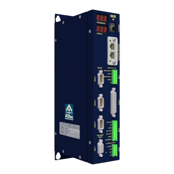
14. Brake Cable 15. Motor Encoder Cable 16. CN1 Cable 17. STO Cable ⚫ SERVO CONTROLLER 18. OACIS-1XC 19. Firmware Download Cable ⚫ ETC 20. Quick Installation Guide 21. CD-ROM with Setup Software ... - Page 3 Quick Installation Diagram Check Up the Package Hardware Installation Software Installation OACIS Power On...
- Page 4 I. Check up the Package Case I. One Servo Press with OACIS-1XC ○ ○ ○ ○ ○ ○ ○ ○ ○ ○ ○ ○ ○ Case II. One Nut Runner with OACIS-1XC ○ ○ ○ ○ ○ ○...
- Page 5 DO NOT CONNECT ALL THE CABLES WITH POWER ON. All the wirings should be connected after switch off. Otherwise severe damage for the devices might happen.
-
Page 6: Hardware Installation
II. Hardware Installation Connect OACIS Power In & Ground ✓ It is recommended to separate Power In Connection from frequent Turn On and Off circuit like Light Curtain Connect Analog Inputs ✓ Each Analog Input Channel has its own GND terminal. ✓... -
Page 7: Limit Sensor
Connect Home & Limit Sensors LIMIT SENSOR (PROXIMITY SENSOR) LIMIT SENSOR (PROXIMITY SENSOR) HOME SENSOR HOME SENSOR (CONTACT SENSOR) (CONTACT SENSOR) BROWN-24V BLACK -Sensing Signal BROWN-24V BLUE-0V BLUE-HOME Home sensor cable should be connected with power off. Connect Servo Motor and Drive ✓... - Page 8 ✓ Keep the encoder cable away from the power cable wiring by 300 mm or more. ✓ Do not guide the encoder cable through the same duct as the power cable, nor bind them together. THREE PHASE DIRECT CURRENT 380V ±10% 24V ±10% +24V OACIS-2XC...
- Page 9 Servo Drive OACIS Limit Sensor Cables Brake & Brake Common Drive Power (3Ø, 220V) Servo Motor OACIS GND Power Motor GND Cable Chassis GND Brake Cable Encoder Power Cable Brake Cable Encoder Cable 300 mm or more!!
-
Page 10: Safety Circuits
Safety Circuits ✓ The circuits should meet ISO standard safety requirement. -. EN ISO 13849-1 / 14121-1 -. EN/IEC 61508 -. EN/IEC 62061 ✓ Safety circuit example for Cat 3... - Page 11 Servo Drive...
- Page 12 This circuit does not meet ISO standard safety requirement. It can cause severe damage to the operator or people who work for maintenance. So, any kinds of damage caused by this operation is not responsibility of ATA ✓ Potential quality related issues with stop and resume function.
-
Page 13: Software Installation
III. Software Installation Install OACIScom. ✓ Double click “…\OACIScom_v4.01.02.01\setup.exe” Special Settings for Window 7 ✓ Desktop → OACIScom Icon right click → Properties →Compatibility mode check → Privilege Level check... - Page 14 Connect to OACIS. ✓ PC IP Address needs to be set properly as shown below. It is strongly recommended that the Ethernet cable be directly connected to OACIS without any communication hub. Do not combine the network PLC and OACIS ✓...
- Page 15 Connect to EtherNet/IP Module OACIS-1XC ✓ EtherNet/IP module IP address needs to be set properly as shown below. ✓ Install ‘IP Config’ application and Run the program. ◼ You can download ‘IP Config’ application from ATA or HMS website, https://www.anybus.com/support/file-doc-downloads/anybus-support- tools?orderCode=tools...
- Page 16 ✓ Double-click on its entry in the list. And the network information will be updated if you click Set after changing IP address and subnet mask properly. ✓ Default IP address is 192.168.3.3 ✓ When the program runs, the network is automatically scanned for EtherNet/IP module products.
- Page 17 IV. OACIS Power On Turn ON the Servo Drive & OACIS power after confirming a proper wiring. OACIS Check up the LoadCell ✓ With your hands, please press the shaft of servo press upward and downward. See the value of analog inputs is reasonable. OACIScom Confirm the Brake Wiring of Servo Motor.
-
Page 18: Servo Controller
+24 VDC 0 VDC MOTOR BRAKE SERVO CONTROLLER OACIS BRAKE BRAKE COMMON Move Jog. ✓ You can move an axis forward or backward manually by operating COMMAND menu. It comes in quite handy when you build the machine up for the first time or some errors happen with high load. - Page 19 Homing. Select “OPERATING” tab on the Command window. ✓...
Need help?
Do you have a question about the OACIS-1XC and is the answer not in the manual?
Questions and answers