Table of Contents
Advertisement
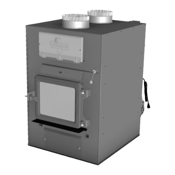
Owner's Installation and Operation Manual
This manual includes Installation and
operation instructions for the Model
CF700M Furnace utilizing the listed
operational types:
1. Wood add-on
2. Wood only
Installation is to be preformed by a
qualified installer.
SAVE THESE INSTRUCTIONS
This unit is certified UL 391
U.S. ENVIRONMENTAL PROTECTION AGENCY
Certified to comply with the 2016 particulate
emission standards. Not approved for sale after
May 15, 2020
Model CF700M
United States Stove Company
227 Industrial Park Rd.
South Pittsburg, TN 37380
TM
852511-0804F
Advertisement
Table of Contents

Related Manuals for Clayton CF700M

Summary of Contents for Clayton CF700M
- Page 1 Owner’s Installation and Operation Manual Model CF700M This manual includes Installation and operation instructions for the Model CF700M Furnace utilizing the listed operational types: 1. Wood add-on 2. Wood only Installation is to be preformed by a qualified installer. SAVE THESE INSTRUCTIONS This unit is certified UL 391 U.S.
- Page 2 CAUTION: • The warm air supply outlet of the supplementary furnace shall not be connected to the cold-air return inlet of the central furnace because a possibility exists of components of the central furnace overheating and causing the central furnace to operate other than as intended. •...
-
Page 3: Specifications
13” x 10.75” (330mm x 273mm) Weight (lbs): This manual describes the installation and operation of the Clayton, CF700M wood heater. This heater meets the 2017 U.S. Environmental Protection Agency’s emission limits for wood heaters sold after May 15, 2016. Under specific EPA test conditions this heater has been shown to deliver heat at a rate of 20,568 –... - Page 4 Safety • Do not operate with fuel loading or ash removal doors open. • Do not connect this unit to a chimney flue serving another appliance. • Danger: Risk of fire or explosion. Do not burn garbage, gasoline, naphtha, motor oil, or other inappropriate materials.
-
Page 5: Tools And Materials Needed For Installation
Unpacking And Preassemble UNPACKING 1. Remove all packaging from the furnace. 2. Remove the supplied tools and parts from the furnace. A. The supplied ash shovel and poker from the heat exchanger tube, behind the heat exchanger door at the top of the unit. BRICK ALIGNMENT Inspect for any damage. -
Page 6: Furnace Installation
Furnace Installation INSTALLATION OPTIONS The installation of this furnace includes supplying electrical power, return (fresh air) ductwork, and supply air ductwork. This furnace may be installed in two different configurations. 1. Stand alone wood furnace 2. Add-on wood furnace See kit installation section in this manual to ensure proper assembly, installation and operation of your new furnace. -
Page 7: Floor Protector Requirements
MAINTENANCE CLEARANCES Your furnace has recommended minimum maintenance clearance requirements. These clearances insure that there is adequate room to preform maintenance and service your furnace. DO NOT store fuel within the specified clearances. The clearances will change depending on what kits are installed with your furnace. See the tables and diagram below to determine the clearances for your furnace. -
Page 8: Duct Work Installation
Duct Work Installation We strongly recommend that the hot air ductwork be installed by a home heating specialist. If doing the installation yourself, before you decide which installation will best suit your needs, consult a qualified heating technician and follow his recommendations as to the safest and most efficient method of installation. This furnace can be installed in three ways, as a stand alone unit, parallel, and in series with an existing furnace. -
Page 9: Stand Alone Installation
STAND ALONE INSTALLATION If installing this furnace as a stand alone unit, ensure all local codes and all instructions in this manual are followed, including clearance to combustibles, floor protector specifications and safety warnings. PARALLEL FURNACE INSTALLATION To install the new furnace in parallel with an existing furnace follow the instructions for series installation with a few additional requirements listed below. -
Page 10: Add-On Installation
CENTRAL INSTALLATION ADD-ON INSTALLATION... - Page 11 INSTALLATION A TO EXISTING DUCT WORK COLD AIR RETURN WARM AIR EXISTING FURNACE SOLID FUEL FILTER BOX INSTA FURNACE INSTALLATION B TO EXISTING COLD AIR DUCT WORK RETURN PLENUM COLLECTOR WARM AIR PLENUM TOP (OPTIONAL) COLD AIR RETURN EXISTING FURNACE FILTER BOX FILTER BOX SOLID FUEL...
- Page 12 INSTALLATION D INSTALLATION E...
-
Page 13: Top View
INSTALLATION F INSTALLATION G INSTALLATION H TOP VIEW FRONT VIEW... -
Page 14: Accessory Installation
Accessory Installation ASSEMBLY OF FURNACE Your furnace requires the following items to be assembled or installed by the service person: Blowers and Blower Controls Electrical Connections 1. Remove all parts from inside the furnace and inspect for damage, including the firebrick as some breakage could occur during shipment. -
Page 15: Electrical Installation
Electrical Installation All electrical connections should be done by a qualified electrician It is recommended to connect the furnace to its own 15 amp 120 Volt circuit from the house power supply 105°C NOTE:Wire leads from the distribution blower are usually BOTH BLACK. -
Page 16: Chimney Installation
Chimney Installation CHIMNEY Your wood furnace may be hooked up with a factory built or masonry chimney, matching the diameter of the exhaust. If you are using a factory built chimney, it must comply with UL 103 or CSA-B365 standard; therefore it must be a Type HT (2100°F). -
Page 17: Masonry Chimney
MASONRY CHIMNEY Ensure that a masonry chimney meets the minimum standards of the National Fire Protection Association (NFPA) by having it inspected by a professional. Make sure there are no cracks, loose mortar or other signs of deterioration and blockage. Have the chimney cleaned before the furnace is installed and operated. When connecting the furnace through a combustible wall to a masonry chimney, special methods are needed as explained in the “Combustible Wall Chimney Connector Pass-Throughs”... -
Page 18: Combustible Wall Chimney Connector Pass-Throughs
COMBUSTIBLE WALL CHIMNEY CONNECTOR PASS-THROUGHS Method A. 12” (304.8 mm) Clearance to Combustible Wall Member: Using a minimum thickness 3.5” (89 mm) brick and a 5/8” (15.9 mm) minimum wall thickness clay liner, construct a wall pass-through. The clay liner must conform to ASTM C315 (Standard Specification for Clay Fire Linings) or its equivalent. -
Page 19: Chimney Connector
CHIMNEY CONNECTOR Your chimney connector and chimney must have the same diameter as the furnace outlet. If this is not the case, we recommend you contact your dealer in order to insure there will be no problem with the draft. The furnace pipe must be made of aluminized or cold roll steel with a minimum thickness of 0.021”... -
Page 20: Factory Built Chimney
FACTORY BUILT CHIMNEY When a metal prefabricated chimney is used, the manufacturer’s installation instructions must be followed. You must also purchase (from the same manufacturer) and install the ceiling support package or wall pass-through and “T” section package, firestops (where needed), insulation shield, roof flashing, chimney cap, etc. Maintain proper clearance to the structure as recommended by the manufacturer. -
Page 21: Wood Heat Utilization
Wood Heat Utilization The top down method of fire building is recommended for this appliance. After making sure that the stove air intake controls are fully open (completely pull-out towards you), Place the largest pieces of wood on the bottom, laid in parallel and close together. -
Page 22: Operation
Operation NOTICE: To minimize the risk of smoke spillage when opening the door with a fire in your furnace, crack the door open no more than 1” and wait for at least 10 seconds before opening it more to allow pressure stabilization inside the furnace. -
Page 23: To Prevent Creosote Build Up
OPERATION Controlled combustion is the most efficient technique for wood heating because it enables you to select the type of combustion you want for each given situation. The wood will burn slowly if the wood furnace air intake control is adjusted to reduce the oxygen supply in the combustion chamber to a minimum. On the other hand, wood will burn quickly if the air control is adjusted to admit a larger quantity of oxygen in the combustion chamber. -
Page 24: Over Firing
CAUTIONS: • Ashes could contain hot embers even after two days without operating the furnace. • The ash pan can become very hot. Wear gloves to prevent injury. • Never burn the furnace with the ash trap open. This would result in over firing the furnace. Damage to the furnace and even house fire may result. -
Page 25: Maintenance
Maintenance Your wood furnace is a high efficiency furnace and therefore requires little maintenance. It is important to perform a visual inspection of the furnace every time it is emptied, in order to insure that no parts have been damaged, in which case repairs must be performed immediately. Inspect and clean the chimney and connector pipe periodically for creosote buildup or obstructions. -
Page 26: Replacement Parts
Replacement Parts Part No. Description Qty. Part No. Description Qty. 27312G Side Panel 40627 Heat Exchange Door 891214 Stub Collar, 8” 892351 Exchange Handle 27322 Top Panel 27327 Air Damper 27329 Cabinet Back 26866 Door Latch 26761 Hearth Plate 892503 Damper Handle 26765 Air Wash Plate... - Page 27 Replacement Parts Part No. Description 891135 Handle, Spring (Lg-Nickel) 892347 Door Handle 40603 Cast Door 88082 Thermocord 3/4” 50” 88087 Glass Gasket (1 X 1/8) 892346 Door Glass 26848 Window Clamp 26856 Door Cover Plate In order to maintain warranty, components must be replaced using original manufacturers parts purchased through your dealer or directly from the appliance manufacturer.
- Page 28 Replacement Parts Part No. Description 27312 Side Panel 891414 Half Firebrick 26596 Firebrick Notched (4-1/2 X 9) 88213 Side Blanket 89066 Firebrick (4-1/2 X 9) 24103 Firebrick, Half (4-1/2 X 4-1/2) 88212 Base Blanket 40561 Ash Plug 88210 Baffle Board 86757 Tube, Air Secondary 83874...
- Page 29 Replacement Parts Part No. Description 68234 Assy, Blower/T’stat Brkt. 68231-1 Fan Cntrl Cord Assy 80131 4 X 4 Junction Box 80232 Supply Cord 68231-2 Fan Cntrl Cord Assy 80230 Blower Assembly 89319 Blower Gasket 68231-3 Fan Cntrl Cord Assy 22140 Control Mounting Bracket 80314 F120 Thermodisc...
- Page 30 Limited Warranty The operation of this wood heater in a manner inconsistent with the owner’s manual will void you warranty and is also against federal regulations. United States Stove Company warrants to the original purchaser its products against premature failure of any component due to workmanship, quality, or materials as follows: TIME PERIOD: Firebox ..........................
-
Page 31: Service Record
Service Record It is recommended that your heating system is serviced regularly and that the appropriate Service Interval Record is completed. Service Provider: Before completing the appropriate Service Record below, please ensure you have carried out the service as described in the manufacturer’s instructions. -
Page 32: How To Order Replacement Parts
How to order Replacement Parts This manual will help you obtain efficient, dependable service from your stove, and enable you to order repair parts correctly. Keep this manual in a safe place for future reference. When writing, always give the full model number which is on the nameplate attached to the stove. When ordering repair parts, always give the following information as shown in this list: 1.
Need help?
Do you have a question about the CF700M and is the answer not in the manual?
Questions and answers