
Subscribe to Our Youtube Channel
Related Manuals for Clou CL7206C


Summary of Contents for Clou CL7206C
- Page 1 User Manual of CL7206C RFID Reader Shenzhen Clou IOT Technologies Co., Ltd (V2.0.2)
- Page 2 Welcome to be user of CLOU RFID products. Thanks for choosing CLOU’s 4-port Fixed RFID Reader CL7206C. We believe our device will bring convenience for your work.
-
Page 3: Table Of Contents
Catalogue 1. Technical Specification ............................6 1.1 Feature .................................... 6 1.2 Technical ..................................6 1.2.1 Main function ..............................6 1.2.2 Technical parameter ............................7 1.2.3 Operational environment ..........................7 2. Sketch map ..................................8 2.1 Physical construction ............................... - Page 4 3.5.1 Acceptance of structure ..........................15 3.5.2 Performance acceptance ..........................16 4. Software operating ..............................17 4.1 Demo software ................................. 17 4.2 Application environment ............................. 17 4.3 Software version ..............................17 4.4 Installation .................................. 17 4.5 Operation ..................................
- Page 5 6. Package ..................................47 6.1 Package ..................................47 6.2 Accessories ................................. 47 6.3 Storage environment ............................. 48 7. After-sale service ..............................52 ...
-
Page 6: Technical Specification
1. Technical Specification 1.1 Feature CL7206C is a high performance eight antenna port fixed UHF RFID reader and writer; support ISO18000-6C/6B protocols. The work frequency includes China standard dual frequency 920MHz ~ 925MHz and 840MHz~845MHz, FCC 902MHz ~ 928MHz and ETSI 865MHz ~ 868MHz. -
Page 7: Technical Parameter
1.2.2 Technical parameter Working frequency: ETSI 865MHz~868MHz Output power (port): 33dBm + 1dB (MAX) Power adjustment: 1 dB step-by-step Reading distance: 0 ~8meters (depending on tags, antennas and environment) Channel bandwidth: <200 KHz RS232 serial communication rate: 115200bps (default), 19200 bps, 9600bps ... -
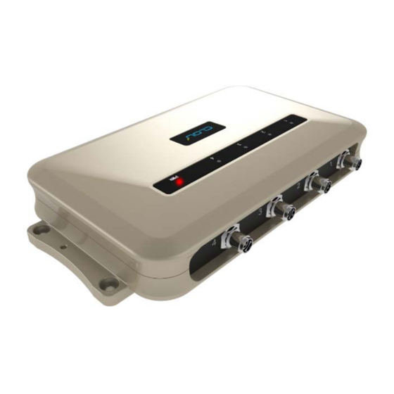
Page 8: Sketch Map
2. Sketch map 2.1 Physical construction Image 2-1 Structure diagram of CL7206C Size: 256mm*147.6mm*43.47mm 2.2 Weight Main body: 1.14kg(accessories excluded) 2.3 Illustration of LED display Image2-2 Sketch map of reader’s LED indicator LED indicator panel describe as below Form 2-1:... -
Page 9: Interfaces
ANT1 Antenna 1 indicator Indicates antenna 1 is working ANT2 Antenna 2 indicator Indicates antenna 2 is working ANT3 Antenna 3 indicator Indicates antenna 3 is working ANT4 Antenna 4 indicator Indicates antenna 4 is working Keep bright indicates power supply working POWER Power indicator normally... -
Page 10: I/O Interface Definition
communication interface. For external U disk, wireless LAN and other expansion USB HOST USB host port devices. RS-232 RS-232 serial port Serial communication interface with control reader. Other I/O interface See detailed definition 2.4.2. 2.4.2 I/O Interface definition Image 2-4 Sketch map of I/O control interface I/O control signal define as follow form 2-3 Form 2-3 I/O control signal definitions PIN Description... - Page 11 Relay output # 2, DC_MAX: 30V, 2A; AC_MAX: 125V, 0.3A; logic '0' indicates the open, a logic '1' means close, the default is open. Relay # 3 output, DC_MAX: 30V, 2A; AC_MAX: 125V, 0.3A; logic '0' indicates the open, a logic '1' means close, the default is open. Relay # 3 output, DC_MAX: 30V, 2A;...
-
Page 12: Feeding Line(Optional)
Wiegand Data 1 signal, the default state is high. Ground 485-A RS485 A-side signal 485-B RS485 B-side signal 2.4.3 Feeding line(optional) Image 2-6 schematic diagram of feeder line RF cable TNC(Reverse polarity, internal thread, inner pin) connector connect with reader antenna TNC connector, RF cable SMA connector connect with external circular polarization antennas SMA connector, cable maximum length is 5m, impedance 50Ω, insertion loss is less than 2dB, or you also can choose a high performance cable, appropriate increase in length, insertion loss is less than 2dB. - Page 13 with the PC network interface, as shown in figure 2-7: Image 2-7 Network application connection diagram...
-
Page 14: Installation
To ensure the normal and stable operation of the device and your personal property and safety, please carefully read the following notes before install CL7206C reader and writer: 1. Firstly, check whether the power socket is connected to the ground, and to see whether the local power supply voltage is in accordance with the applicable voltage range of the reader;... -
Page 15: Antenna Connection
3.3.2 Antenna connection The device built with four TNC coaxial cable connector for connecting an external antenna, select low consumption RF cable, connectors should be tightened (Ensure to be waterproof when install outdoors); The reader antenna angle or corner to adjust to the best position through the actual test according to the specific application,. -
Page 16: Performance Acceptance
Whether the screws are tighten 3.5.2 Performance acceptance Whether the reader is working properly; Whether the read and write range is reasonable. -
Page 17: Software Operating
4. Software operating 4.1 Demo software The demo software mainly carries on system control, communication mode selection, parameter setting and searching, read and write tags and data presentation and so on. Before using the demon software, please check if the connection of the reader hardware is completed, mainly ensure the following tips: 1, If the reader and computer serial port (network or RS485) is connected correctly 2, If the antenna ports have been connected to the antenna (ANT, ANT1 2, ANT 3, ANT totally... -
Page 18: Operation
install. 3. Click the "Install", and software installation progress takes about 1mins. 4. After the progress of the software is finished, click the "finish" button to complete the installation. 4.5 Operation 4.5.1 Device connection All functions can be operated only after successful connection. 4.5.1.1 Serial communication connection Double click the icon to start the Demo software, the main interface of the toolbar... - Page 19 Image 4-6 Serial communication connection If the connection is successful, all the icons in the toolbar are illuminated, as shown in image 4-7, means the serial communication connection is successful.
- Page 20 Imag4-7 serial port communication connect successful 4.5.1.2 Network port communication connection Network port used for long distance connection (within 80 m), connect to the router through cable and switcher, router, or connected with the PC network port directly. Select the communication mode "TCP connection"...
- Page 21 Image 4-8 Network port communication connection The device has been written IP address 192.168.1.116 as default. If you forget or need to modify, using serial connection "connection" after connect successfully, then you can found the current IP address through select “settings” > "senior" > “configuration”, set up the IP address in “Network port settings”...
-
Page 22: Data Display Area
Image 4-10 485 communication connection RS485 address defaults to 1 RS485 address range 1~255 Note: Click the button after changing the configuration 4.5.1.4 USB communication connection Select the communication mode "serial port" in the "connect reader" option list, "connect parameter" select "COM?" (the USB serial number detected by PC), the communication rate is selected "115200"... - Page 23 Image 4-12 data display area parameter meanings Type: label type: 6C, 6B two types EPC: EPC data of tags, can be read and write. TID: the TID data of the label, the only logo, read only User Data: user data area, can be read and write. Reserve Data: reserved area data, store the password data, etc.
- Page 24 Click the button , the data display area will display the current read EPC data EPC display as hexadecimal character string, use the word as length unit (1 word = 2 bytes = 4 hexadecimal character) If you want to read the EPC data of the custom length, please refer to chapter 4.5.2.3 custom read 4.5.2.2 Read TID Click the button...
- Page 25 Image 4-13 6C Tag custom configurations Select the 6B tag configuration, and pop up dialog box as shown in image 4-14 Can choose to read TID data or user data Can matching read TID data. Tip: Customer who not familiar with the label agreement, please ignore this feature...
-
Page 26: Write Data
Image 4-14 6B Tag custom configurations 4.5.2.4 Stop read Click button stop all read and write operations. 4.5.3 Write data 4.5.3.1 Write EPC data Click button and pop up dialog box as shown in image 4-15:... - Page 27 Image 4-15 write EPC data Select a label data (contains TID information) has been read, fill in the EPC data (16 hex string), click "OK". 4.5.3.2 Write user data Click button and pop up dialog box as shown in image 4-16:...
- Page 28 Image 4-16 write user data Select a label data (contains TID information)has been read, fill in the user data (16 hex string), click "OK". 4.5.3.3 Custom tag action Click button and pop up dialog box as shown in image 4-17:...
-
Page 29: Tcp Server / Client Mode
Image 4-17 Custom tag action 1. Select a tag data that has been read; 2. Click the "custom operation" button; 3. Take detailed action to write / lock / destroy tag according to the reader protocol 4.5.4 TCP server / client mode Select configuration on the main demo interface >... -
Page 30: Antenna Configuration
Image 4-18 Mode setting When the reader is configured as a "server" mode, the connection is initiated by PC; when the reader set as a "client" mode, it will connect to the PC side automatically. 4.5.5 Antenna configuration Select" configuration" on the DEMO main interface-- > "senior"-- > "reader configuration ", then pop-up dialog box, as shown in image 4-19. -
Page 31: Base Band Parameter Configuration
Image 4-19 Antenna enable configuration Select all antenna enable configuration, click the "configuration", pop up dialog box, click "OK" means configure succeeds. If the antenna enable is not selected, when select the corresponding reader on the DEMO main interface, will pop up dialogue box as shown in image 4-20. -
Page 32: Antenna Port Power Setting
Image 4-21 Base band parameter configuration Changing the base band parameter configuration can change the actual effect of the read and write (can be reasonably configured according to the application scenarios, but it needs to be operated under the guidance of our engineers). EPC base band rate provides five options: Tair=25us, FM0, LHF=40KHz, dense reading mode;... -
Page 33: Clock Setting
dialog box, as shown in image 4-22. Image 4-22 Antenna port power setting Select the corresponding antenna port (external antenna connected), select the appropriate power values from the power list, click Configure, pop up the configuration of the success of the dialog box, click OK to complete power configuration. -
Page 34: Frequency Hopping
Image 4-23 Clock display setting 4.5.9 Frequency Hopping Click “configuration” on the main interface > RFID configuration > "hopping management", pop-up frequency hopping management dialog box, as shown in image 4-24 Imag 4-24 Frequency Hopping management Select "CMII, 920-925MHz" (see Image 4-25) in the "working band" drop-down list, click the "Settings", select single frequency points from the left frequency list box(see Image 4-24) then... -
Page 35: Label Filtering
click the " " button, right into the list box, and then click the "configuration" to confirm; If you want to select the full band frequency hopping just click all the frequency points will show on the right side of the list box, click the "configuration" to confirm. If you click , all frequency points on the right side of the list box will be cleared. -
Page 36: Buffer And Breakpoint Resume
4.5.11 Buffer and breakpoint resume For make sure the reader ‘s complete collection of rfid tags’ data, CL7206C support tag data-caching mechanism and breakpoint resume, in case that the tag’s data loss because of the communication interrupted or PC application error exit, the tag data by caching mechanism could be saved without power. - Page 37 Image 4-27 tag filter After the validate the breakpoint resume function, the PC will reply each data of tags uploading, reader will automatically save the tag’s data which are not uploaded. PC could operate the saved data through setting Obtain saved data or setting clear saved data. As below image 4-28.
-
Page 38: Auto Idle Set Up
Image 4-28 tag buffer data operation As under the breakpoint resume mode, PC will confirm to each tag data from reader, under mass quantity of tag data will reduce the communication efficiency, increase the system load, we suggest: When start the breakpoint upload functions, according to your application, can set up suitable “tag filter parameter”... -
Page 39: Gpi/O Configuration
Image 4-29 Auto idle configuration Auto idle mode means when the reader continuous reading tags, all using antenna didn’t identify the tags for three times continuously ,then the reader automatically enter a period of idle state to save power consumption, the reader re-enter the card reader automatically after idle time. - Page 40 Imag 4-30 GPI configuration Check: check the various port trigger parameters Configuration: select the port need to set, click button to execute the settings after modify Trigger start condition: select the mode from the drop-down list Trigger execution instruction: select the mode from the drop-down list ...
-
Page 41: Others
Image 4-3 GPO configuration CL7206C reader only supports four GPO outputs, that is "1" “2”, “3”, “4”. Select the high / low level, click this configuration to execute settings after modify. 4.5.14 Others Wigand configuration Select “configuration” on the main interface --> "GPI/O configuration" --> “Wigand "then... -
Page 42: Tools
“Weigand 66"models. Weigand 26: TID or EPC data reported from the end of the Weigand port is valid for 3 bytes. Weigand 34: TID or EPC data reported from the end of the Weigand port is valid for 4 bytes. Weigand 66: TID data reported from the end of the Weigand port is valid for 8 bytes. - Page 43 Image 4-32 Data export Read the tag data to support data export, export format can be.csv (comma file) and.Xls (Excel). Software upgrade The reader support for online upgrade, software upgrades support the baseband software upgrade (the underlying software) and application software upgrades (system software applications).
- Page 44 Image 4-33 Application software upgrade To find the Bin upgrade file path in the upgrade file drop-down list, click upgrade progress bar shows 100% that means the application software upgrade successfully, pop-up upgrade prompted success dialog box, click OK to restart the reader, as shown in image 4-34.
-
Page 45: Common Failures
Check if the selected COM port is right. The network port cannot connect: Factory set the default IP address: 192.168.1.116 when CL7206C reader device ex-factory, ensure the IP address of the PC and reader in the same network segment, such as... - Page 46 you can reset the reader’s IP address through the serial port. The reader can't read the tag Check if the setting of antenna number is correct Check if the label is damaged Check if the label is placed in the reader's valid reading and writing range. Check if the electromagnetic interference between the reader and the other device.
- Page 47 6. Package 6.1 Package Imag6-1 Carton box size 290X290X76MM Carton box size: 6.2 Accessories In order to facilitate the storage and transportation in near future, the packing box and the packing material should be kept properly after unpack. Besides of the device in the box, accessories equipped with the reader are also included in, please check the product packing list to confirm whether the product and accessories are complete, if any discrepancies or damage, please contact with the after-sale service in time.
- Page 48 9dBi circularly polarized antenna 20351000000035 Optional Feeder line SMA-K--TNC-J reversed polarity 20351000000814 Optional Mounting screws M4*28 W01-104028-100 Included 20420000001651 Warranty card Included 20420000001650 Certificate of approval Included N10-010000-002 Optional 6.3 Storage environment CL7206C fixed reader should be stored in below conditions:...
- Page 49 ☆ Environment temperature:-40℃~+85℃ ☆ Relative humidity:5% RH~95%RH...
- Page 50 DECLARATION OF CONFORMITY Hereby,Shenzhen Clou IOT Technologies Co.,Ltd. declares that this Integrated Fixed Reader product in compliance with the essential requirements and other relevant provisions of Directive 1999/5/EC. A copy of the Declaration of Conformity can be found an Website: http://www.clouiotech.com/...
- Page 51 OF USED BATTERIES ACCORDING TO THE INSTRUCTIONS 2. The device complies with RF specifications when the device used at 50cm form your body Care for the environment! Must not be discarded with household waste! This product contains electrical or electronic components that should be recycled. Leave the product for recycling at the designated station, e.g.
- Page 52 Thus the real product may be not in accordance with this manual. Generally, we will provide timely amendments to this manual. If it’s not provided timely, please consult our service department. Shenzhen Clou IOT Technologies Co., Ltd. Tel of Sales Dept: 0755-36901039 Tel of Customer Service Dept: 0755-36901039 Email: RFIDoverseas@szclou.com...
- Page 53 3, The software of this product can be upgraded freely, users can be training in our company for free. 4, Will be charge appropriately if the user don’t have a warranty card. 5, Users will need to fill out the warranty card for repair service, and sent back to CLOU.
Need help?
Do you have a question about the CL7206C and is the answer not in the manual?
Questions and answers