
Related Manuals for Clou CL7206C2


Summary of Contents for Clou CL7206C2
- Page 1 CL7206C2 Four- Port Fixed RFID Reader User Manual (V1.0) Shenzhen Clou IOT Technologies Co., Ltd ...
- Page 2 Welcome to be user of CLOU RFID products. Thanks for choosing CLOU’s Four-Port Fixed RFID Reader CL7206C2. We believe our device will bring convenience for your work.
-
Page 3: Table Of Contents
Catalogue 1. Technical Specification ..........................6 1.1 Product Features ............................6 1.2 Main function and technical features ......................6 1.2.1 Main function ............................6 1.2.2 Technical parameter ..........................7 1.2.3 Operational Environment ........................7 2. Sketch map ..............................8 2.1 Physical construction ..........................8 ... - Page 4 3.5 Acceptance ...............................14 3.5.1 Acceptance of structure ........................14 3.5.2 Performance acceptance ........................14 4. Operating Instruction ..........................15 4.1 Introduction of Demo software ........................15 4.2 Demo software application environment ....................15 4.3 Demo software version ..........................15 4.4 Demo software installation ........................15 ...
- Page 5 4.5.7 Antenna port power setting ........................27 4.5.8 Clock setting ............................27 4.5.9 Frequency Hopping management ......................28 4.5.10 Label filtering ............................29 4.5.11 Auto idle configuration ........................30 4.5.12 GPI/O configuration .........................30 4.5.13 Advanced configuration ........................32 4.5.14 Tools ..............................33 5.
-
Page 6: Technical Specification
1. Technical Specification 1.1 Product Features CL7206C is a high performance four antenna port fixed UHF RFID reader and writer; support ISO18000-6C/6B protocols. The work frequency includes China standard dual frequency 920MHz ~ 925MHz and 840MHz~845MHz, FCC 902MHz ~ 928MHz and ETSI 865MHz ~ 868MHz. Output power from 0 ~ 33dBm optional, with long identification distance, fast reading speed, high accurate rate, strong anti-interference ability, good protection performance and easy installation 1.2 Main function and technical features... -
Page 7: Technical Parameter
1.2.2 Technical parameter Working frequency: GB 920MHz~925MHz, GB 840MHz~845MHz, FCC 902MHz~928MHz, ETSI 865MHz~868MHz Output power (port): 33dBm + 1dB (MAX) Power adjustment: 1 dB step-by-step Reading distance: 0 ~8meters (depending on tags, antennas and environment) Channel bandwidth: <200 KHz RS232 serial communication rate: 115200bps (default), 19200 bps, 9600bps RS485 interface communication rate: 115200bps (default), 19200 bps, 9600bps Support: Weigand 26, 34, 66 interfaces Power supply: 30V ~ 10V (power capacity is not less than 60W) -
Page 8: Sketch Map
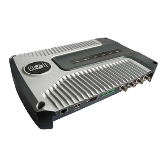
2. Sketch map 2.1 Physical construction Image 2-1 Structure diagram of CL7206C2 Volume of four-port fixed rfid reader CL7206C2: 324mm*225mm*62mm(accessories excluded) 2.2 Weight About 2.6kg(accessories excluded) 2.3 Illustration of LED display Image2-2 Sketch map of reader’s LED indicator LED indicator panel describe as below Form 2-1:... -
Page 9: Sketch Map Of Interfaces
Form 2-1 LED indicator description LED Mark NO. Mark NO. Status description ANT1 Antenna 1 indicator Indicates antenna 1 is working ANT2 Antenna 2 indicator Indicates antenna 2 is working ANT3 Antenna 3 indicator Indicates antenna 3 is working ANT4 Antenna 4 indicator Indicates antenna 4 is working Status... - Page 10 Image 2-4 Sketch map of I/O control interface I/O control signal define as follow form 2-3 Form 2-3 I/O control signal definitions Aviation pin description of pin pin definitions Relay 1 output port OUT_R1 Relay 2 output port OUT_R2 Relay 3 output port OUT_R3 Relay 4 output port OUT_R4...
-
Page 11: Schematic Diagram Of Usb Interface
optocoupler 4 external signal input positive IO_INPUT4 optocoupler 2 external signal input positive IO_INPUT2 Relay 4 output port OUT_L4 Relay 3 output port OUT_L3 Relay 2 output port OUT_L2 Relay 1 output port OUT_L1 2.4.3 Schematic diagram of USB interface USB interface application: 1: Application software online upgrade (as shown in figure 2-5 “USB interface") 2: USB communications, serial port and network communication all in one (as shown in figure 2-5 USB... -
Page 12: Network Application Connection Diagram
insertion loss is less than 2dB, or you also can choose a high performance cable, appropriate increase in length, insertion loss is less than 2dB. Note: If Ultra long RF cable or the cable joint is not contacted well, may cause performance deterioration on the read and write because of the emission signal and the received echo signal’s attenuation. -
Page 13: Installation Instructions
3. Installation instructions 3.1 Notes To ensure the normal and stable operation of the device and your personal property and safety, please carefully read the following notes before install CL7206C reader and writer: 1. Firstly, check whether the power socket is connected to the ground, and to see whether the local power supply voltage is in accordance with the applicable voltage range of the reader;... -
Page 14: Pc Connection
The reader antenna angle or corner to adjust to the best position through the actual test according to the specific application,. 3.3.3 PC connection The device provides special adapter cable, including interface of network, serial and power; RS232 interface is for short distance communication (less than 10m), through the DB9 connector and the PC serial port connection to realize the communication of PC and the device. -
Page 15: Operating Instruction
4. Operating Instruction 4.1 Introduction of Demo software The demo software mainly carries on system control, communication mode selection, parameter setting and searching, read and write tags and data presentation and so on. Before using the demon software, please check if the connection of the reader hardware is completed, mainly ensure the following tips: 1, If the reader and computer serial port (network or RS485) is connected correctly 2, If the antenna ports have been connected to the antenna (ANT, ANT1 2, ANT 3, ANT totally four ports) -
Page 16: Demo Software Operation
4.5 Demo software operation 4.5.1 Connect the reader All functions can be operated only after successful connection. 4.5.1.1 Serial communication connection Double click the icon to start the Demo software, the main interface of the toolbar icons are gray means reader is not connected, in the ‘connecting reader’ option list select communication mode ‘serial connection’, ‘connection parameters’... -
Page 17: Network Port Communication Connection
Imag4-7 serial port communication connect successful 4.5.1.2 Network port communication connection Network port used for long distance connection (within 80 m), connect to the router through cable and switcher, or connected with the PC network port directly. Select the communication mode "TCP connection" in the "connect reader"... -
Page 18: Rs485 Communication Connection
select “settings” > "senior" > “configuration”, set up the IP address in “Network port settings” when “configuration” dialog pops up. Note: The IP address of the reader can’t be repeated. Use the Ping command to test whether the network is connected on PC. Image 4-4 Settings of reader 4.5.1.3 RS485 communication connection Select the communication mode in the "connect to the reader"... -
Page 19: Usb Communication Connection
Note: Click the button after changing the configuration 4.5.1.4 USB communication connection Select the communication mode "serial port" in the "connect reader" option list, "connect parameter" select "COM?" (the USB serial number detected by PC), the communication rate is selected "115200" (the default value), and click OK button, as shown in image 4-11. -
Page 20: Read Epc
Image 4-12 data display area parameter meanings Type: label type: 6C, 6B two types EPC: EPC data of tags, can be read and write. TID: the TID data of the label, the only logo, read only User Data: user data area, can be read and write. Reserve Data: reserved area data, store the password data, etc. -
Page 21: Custom Read
4.5.2.3 Custom read Click the button , pop-up dialog box, as shown in Image 4-13 Select "6C tag configuration" Matching read, you can matching read through known EPC data or TID data of tags. Read TID, select to read the tag TID data, the read mode default as "adaptation", use the word as length unit. Read the user area, select to read the tag user area data, use the word as the starting address and read length unit Read the reserved area, select to read the tag retains data, use the word as the starting address and read... -
Page 22: Stop Read
Image 4-13 6B Tag custom configurations 4.5.2.4 Stop read Click button stop all read and write operations. 4.5.3 Write data 4.5.3.1 Write EPC data Click button and pop up dialog box as shown in image 4-15:... -
Page 23: Write User Data
Image 4-15 write EPC data Select a label data (contains TID information) has been read, fill in the EPC data (16 hex string), click "OK". 4.5.3.2 Write user data Click button and pop up dialog box as shown in image 4-16: Image 4-16 write user data... -
Page 24: Custom Tag Action
Select a label data (contains TID information)has been read, fill in the user data (16 hex string), click "OK". 4.5.3.3 Custom tag action Click button and pop up dialog box as shown in image 4-17: Image 4-17 Custom tag action 1. -
Page 25: Antenna Enable Configuration
Image 4-18 Mode setting When the reader is configured as a "server" mode, the connection is initiated by PC; when the reader set as a "client" mode, it will connect to the PC side automatically. 4.5.5 Antenna enable configuration Select" configuration" on the DEMO main interface-- > "senior"-- > "reader configuration ", then pop-up dialog box, as shown in image 4-19. -
Page 26: Base Band Parameter Configuration
configure succeeds. If the antenna enable is not selected, when select the corresponding reader on the DEMO main interface, will pop up dialogue box as shown in image 4-20. Image 4-20 Antenna selection 4.5.6 Base band parameter configuration Select "configuration" on the DEMO main interface --> "senior" --> "reader", then pop-up dialog box, as shown in image 4-21. -
Page 27: Antenna Port Power Setting
Q values provide sixteen options: 0/ single label; 1; 2; 3; 4/ multi label; 5; 6; 7; 8; 9; 10; 14; 11; 12; 13; 15. There are three options for searching tags: one sided search; inventory only with Flag B; double search. 4.5.7 Antenna port power setting Select "configuration"... -
Page 28: Frequency Hopping Management
Image 4-23 Clock display setting 4.5.9 Frequency Hopping management Click “configuration” on the main interface > RFID configuration > "hopping management", pop-up frequency hopping management dialog box, as shown in image 4-24 Imag 4-24 Frequency Hopping management Select "CMII, 920-925MHz" (see Image 4-25) in the "working band" drop-down list, click the "Settings", select single frequency points from the left frequency list box(see Image 4-24) then click the "... -
Page 29: Label Filtering
Image 4-25 Frequency Band selection Note: The purpose of setting up the "automatic" is to avoid the interference of the external signal and select the fast frequency hopping. The default configuration for general application is automatically (as shown red mark dropdown list in image 4-24). -
Page 30: Auto Idle Configuration
and discarded. 4.5.11 Auto idle configuration Select "configuration" on the main interface > "RFID configuration" > "auto idle ", then pop-up dialog box, as shown in image 4-27: Image 4-27 Auto idle configuration Auto idle mode means when the reader continuous reading tags, all using antenna didn’t identify the tags for three times continuously ,then the reader automatically enter a period of idle state to save power consumption, the reader re-enter the card reader automatically after idle time. - Page 31 Imag 4-28 GPI configuration Check: check the various port trigger parameters Configuration: select the port need to set, click button to execute the settings after modify Trigger start condition: select the mode from the drop-down list Trigger execution instruction: select the mode from the drop-down list ...
-
Page 32: Advanced Configuration
CL7206C reader only supports two GPO outputs, that is "1" and "2". Select the high / low level, click this configuration to execute settings after modify. 4.5.13 Advanced configuration Weigand configuration Select “configuration” on the main interface > "GPI/O configuration" > “Weigand "then pop-up dialog box, as shown in image 4-30: Image 4-30 Weigand configuration In the Weigand parameter settings area, set up the “communication switch”... -
Page 33: Tools
Image 4-31 restore factory settings When connected to the reader in any form, click OK button, and all settings of the reader will be restored to the factory setting. 4.5.14 Tools Data export Select "tools" on the main interface > "data export" > "form (*. XLS), in the pop-up dialog box, as shown in image 4-32, select the required export file save path. - Page 34 underlying software) and application software upgrades (system software applications). Select "tools" on the main interface > "software upgrade" > "software", the pop-up dialog box, as shown in image 4-33: Image 4-33 Application software upgrade To find the Bin upgrade file path in the upgrade file drop-down list, click the upgrade progress bar shows 100% that means the application software upgrade successfully, pop-up upgrade prompted success dialog box, click OK to restart the reader, as shown in image 4-34.
-
Page 35: Common Failures
5. Common failures 5.1 Daily maintenance The routine maintenance of CL7206C usage: ☆To check whether the tightening of RF connector ☆To check if the screw fixed reader and antenna is loose ☆To check whether the RF cable joints appear outsourcing breaking the shielding layer ☆To check if the reader power line connection is reliable 5.2 Common failure analysis and solution Power supply system failures:... - Page 36 Check if the setting of antenna number is correct Check if the label is damaged Check if the label is placed in the reader's valid reading and writing range. Check if the electromagnetic interference between the reader and the other device. For the problem users cannot solve, please contact customer service.
-
Page 37: Packing Accessories, Transportation And Storage
6. Packing accessories, transportation and storage 6.1 Package Imag6-1 Carton box size 362 mm×250 mm×106mm Carton box size: 6.2 Accessories In order to facilitate the storage and transportation in near future, the packing box and the packing material should be kept properly after unpack. Besides of the device in the box, accessories equipped with the reader are also included in, please check the product packing list to confirm whether the product and accessories are complete, if any discrepancies or damage, please contact with the after-sale service in time. -
Page 38: Storage Environment
Name Material Code Unit Remark CL7206C four-port fixed reader —————— Included Power adapter 24V/2.5A 20109000000324 Included AC power cord 20350000000195 unit Included Network cable 20350000000188 unit Included RS232 blackcable 20351000000478 Included USB cable 20351000000036 Included 9dBi circularly polarized antenna 20351000000035 Included Feeder line SMA-K--TNC-J 50ohm 3m 20351000000038... -
Page 39: After-Sale Service
Thus the real product may be not in accordance with this manual. Generally, we will provide timely amendments to this manual. If it’s not provided timely, please consult our service department. Shenzhen Clou Electrical Technology Co., Ltd. Tel of Sales Dept: 0755-36901166-3302 Fax: 0755-26719679... - Page 40 3, The software of this product can be upgraded freely, users can be training in our company for free. 4, Will be charge appropriately if the user don’t have a warranty card. 5, Users will need to fill out the warranty card for repair service, and sent back to CLOU.
Need help?
Do you have a question about the CL7206C2 and is the answer not in the manual?
Questions and answers