Advertisement
Quick Links
Advertisement

Related Manuals for JOYTECH PY600AC

Summary of Contents for JOYTECH PY600AC
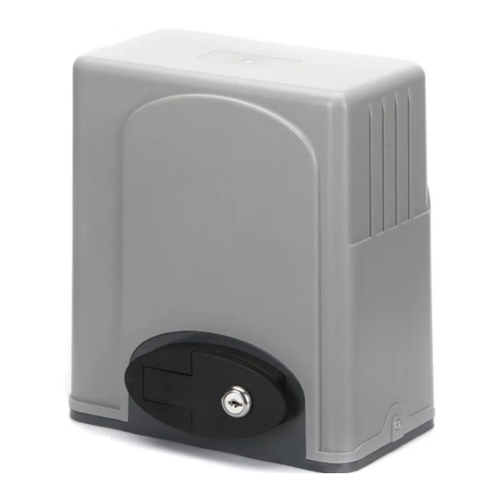
- Page 1 PY600AC Sliding Gate Opener User Manual 2017...
-
Page 2: Safety Instruction
Dear users, Thank you for choosing this product. Please read the manual carefully before assembling and using it. Please do not leave out the manual if you send this product to a third party. 1. Safety Instruction Please ensure that the using power voltage matches with the supply voltage of gate opener (AC110V or AC220V);... - Page 3 2. Packing List (standard) Picture Name Quantity Main engine Manual release key Remote control Spring limit switch accessories box / Magnetic limit switch accessories box Spring limit switch block / Magnetic limit switch block Foundation bolt M8 Limit switch block mounting screw M6X18 Nut M8 Flat washer Ø8...
-
Page 4: Technical Parameters
Steel gear rack 1m/pc Nylon gear rack 1m/pc Infrared sensor Wireless keypad Alarm lamp Mounting plate Protect cover for output gear 3. Technical parameters PY600AC Model Power supply 220V/50Hz;110V/60Hz Motor power 280W Gate moving speed 13m/min Maximum weight of gate 600Kg ≥30m... -
Page 5: Installation
9.4Kg 4. Installation PY600AC sliding gate opener is applicable to gate weight less than 600kg, and length of the sliding gate should be less than 12m. The drive mode adopts the gear and rack transmission. This gate opener must be installed inside the enclosure or yard for protection. - Page 6 Figure 2 (1) Spring Limit Switch Figure 2 (2) Magnetic Limit Switch 4.2.2 Size of mounting plate 204±0.3 Figure 3...
- Page 7 Please cast a concrete pedestal with the size of 400mm x 250mm and depth of 200mm in advance, Please verify whether the distance between the so as to firmly install PY600AC gate opener. gate and gate opener is suitable before casting the pedestal.
- Page 8 Turn on 90° Figure 5 4.3.3 Gear rack installation Fix the mounting screws to the rack. Put the rack on the output gear, and weld the mounting screw to the gate (each screw with one solder joints firstly). ...
- Page 9 Warnings · To ensure safety, install safety stop blocks on both ends of the rails to prevent the gate out of the rail. Before installing the main engine, make sure that the safety stop blocks are in place and whether it has the function of preventing the gate from moving out of the rail and out of the safety range.
- Page 10 Magnetic limit switch - The installation site of magnetic limit switch is shown in Figure 10: ≤20mm Gate Gate Magnets Magnets Magnetic Magnetic limit limit switch switch stop stop block block Gear Gear rack rack Output Output gear gear Figure 10 The installation of magnetic limit switch block is shown in Figure 11: Left side mounting Right side mounting...
- Page 11 4.3.5 Control board wiring 4.3.5.1 Standard control board Lamp Lamp Capacitor Capacitor Motor Motor Earth Earth Power Power D2 D1 D1 C C W U V PE PE N L 10A 250V 250V 24VDC 24VDC 24VDC 24VDC Infrared Infrared sensor sensor CLLM CLLM...
- Page 12 DIP Switch 1. External button switch. ON - Three button switch; OFF - One button switch (X7 terminal CLS button can be used to circularly control the main engine OPEN/STOP/CLOSE /STOP). 2. Automatic close time. 3. Automatic close time. 2 ON 3 OFF: automatic close time is 15s, 2 OFF 3 ON: automatic close time is 30s, 2 OFF 3 OFF: automatic close time is 45s, 2 ON 3 ON: no automatic close function.
- Page 13 Adjustment and operation Remote control operation When remote control is three button mode, three buttons on the remote control to control the main engine OPEN/CLOSE/STOP separately. When remote control is single button mode, one same button on the remote control to circularly control the main engine OPEN/STOP/CLOSE/STOP.
- Page 14 4.3.5.1 Intelligent control board Limit Limit switch switch Loop Loop detetcor detetcor Infrared Infrared sensor sensor 12VDC 12VDC Pedestrian Pedestrian switch switch Capacitor Capacitor O/S/C O/S/C switch switch External External button button switch switch MOT1 MOT1 MOT2 MOT2 Lamp Lamp Earth Earth Power...
- Page 15 9. GND 10. Loop detector (sensor coil) connector (N.O.) In the closing process, once vehicles are detected by the loop detector, the gate will open soon; when the vehicle passes, the gate will close automatically. When the gate is in a halted state, it will keep this state when vehicles are detected;...
- Page 16 3 ON 4 ON: automatic close time is 36s, 3 OFF 4 OFF: no automatic close function. 5. Must at ON position (PY600AC without obstacle detection function, must put 5 at ON position). Infrared connection Infrared photocell function: In the closing process, when infrared ray of the infrared sensor is covered, the gate will open immediately, to protect user and property security.
- Page 17 Adjustment and operation Remote control operation When remote control is three button mode, three buttons on the remote control to control the main engine OPEN/CLOSE/STOP separately. When remote control is single button mode, one same button on the remote control to circularly control the main engine OPEN/STO /CLOSE/STOP.
-
Page 18: Troubleshooting
5.2 Troubleshooting Problems Possible Reasons Solutions The gate cannot open 1.The power is off. 1.Switch on the power supply. or close normally, and 2.Fuse is burned. 2.Check the fuse (code FU), LED does not light. 3.Control board power wiring with change the fuse if burnt.
Need help?
Do you have a question about the PY600AC and is the answer not in the manual?
Questions and answers