
Subscribe to Our Youtube Channel
Related Manuals for Magnum MLT4060MV


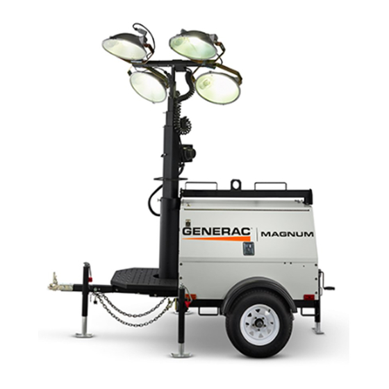
Summary of Contents for Magnum MLT4060MV
- Page 1 POWER PRODUCTS LLC LIGHT TOWER MLT4060MV • MLT4060KV MLT4080KV 00121 OPERATING MANUAL Parts manuals available online! www.m-p-llc.com...
-
Page 2: Introduction
Magnum Power Products LLC, or can be found at www.m-p-llc.com.The information contained in this manual was based on machines in production at the time of publication. Magnum Power Products LLC reserves the right to change any portion of this information without notice. -
Page 3: Table Of Contents
UNIT SERIAL NUMBER LOCATIONS .................... 12 COMPONENT LOCATIONS ......................13 LIGHT TOWER SET UP........................14 RAISING THE MAST........................15 MAIN CONTROL PANEL - MLT4060MV, MLT4060KV ..............16 MAIN CONTROL PANEL - MLT4080KV ..................17 PRESTART CHECKLIST ......................... 18 STARTING THE UNIT........................18 AUTOMATIC SHUTDOWN ...................... -
Page 4: Safety Notes
SAFETY NOTES This is the safety alert symbol. It is used to alert you to potential personal injury hazards. Obey all safety messages that follow this symbol to avoid possible injury or death. This manual contains DANGERS, WARNINGS, CAUTIONS, NOTICES and NOTES which must be followed to prevent the possibility of improper service, damage to the equipment, personal injury or death. -
Page 5: Engine Safety
• ALWAYS extend the outriggers and level the unit before raising the mast. DO NOT retract the outriggers while the mast is up. • If for any reason any part of the mast hangs up or the winch cable develops slack while raising or lowering the mast, STOP immediately and contact an authorized service representative. -
Page 6: Service Safety
SERVICE SAFETY This unit uses high voltage circuits capable of causing serious injury or death. Only a qualified electrician should troubleshoot or repair electrical problems occurring in this equipment. • Before servicing, make sure the Engine Start switch is turned to OFF, circuit breakers are open (off) and the negative terminal on the battery is disconnected. -
Page 7: Reporting Trailer Safety Defects
REPORTING TRAILER SAFETY DEFECTS If you believe your trailer has a defect which could cause a crash or could cause injury or death, you should immediately inform the National Highway Traffic Safety Administration (NHTSA) in addition to notifying Magnum Power Products LLC. -
Page 8: Safety Symbol Summary
SAFETY SYMBOL SUMMARY This equipment has been supplied with numerous safety and operating decals. These decals provide important operating instructions and warn of dangers and hazards. Replace any missing or hard-to-read decals and use care when washing or cleaning the unit. Decal placement and part numbers can be found in the parts manual. Below is a summary of the intended meanings for the symbols used on the decals. -
Page 9: Specifications - Mlt4060Mv, Mlt4060Kv
SPECIFICATIONS - MLT4060MV, MLT4060KV MAGNUM MODEL MLT4060MV MLT4060KV Engine Make/Brand..............Mitsubishi ........Kubota Model ................L3E-W461ML........ D1005-E3BG1-MGM-1 EPA Tier ................ 4f........... 4f Type ................Diesel, liquid cooled, 4-stroke..Diesel, liquid cooled, 4-stroke Horsepower - prime hp (kW) ........10.5 (7.8) ........11.7 (8.7) Horsepower - standby hp (kW) ........ -
Page 10: Specifications - Mlt4080Kv
SPECIFICATIONS - MLT4080KV MAGNUM MODEL MLT4080KV Engine Make/Brand.......................... Kubota Model ........................... D1105-E3BG EPA Tier ..........................4f Type ............................. Diesel, liquid cooled, 4-stroke Horsepower - prime hp (kW) ....................13.5 (10.1) Horsepower - standby hp (kW) ................... 15.4 (11.5) Operating Speed rpm ......................1800 Displacement in (L) ......................68.53 (1.12) -
Page 11: Unit Dimensions
UNIT DIMENSIONS 00213 MLT4060MV/KV, 115 in 107 in 25 ft 68 in 140 in MLT4080KV (2.92 m) (2.71 m) (7.6 m) (1.73 m) (3.56 m) Specifications are subject to change without notice. -
Page 12: Unit Serial Number Locations
1-800-926-9768 Model Serial Number VIN Tag Mfg. Code Skidded WT (lbs/kg) rpm/freq TIRE AND LOADING INFORMATION MANUFACTURED BY/FABRIQUE PAR: Magnum Power Products LLC DATE: 00/0000 1 ph. 1.0PF 3 ph. .8PF 3 ph. 1.0PF GVWR/PNBV: 000KG (0000LBS) COLD INF. PRESS./... -
Page 13: Component Locations
COMPONENT LOCATIONS Central Lift Point Control Engine Exhaust Mast Switch Battery Forklift Pockets LEFT SIDE Radiator Access Mast Rotation Knob Engine Fuel Fill Access Outriggers RIGHT SIDE 00109... -
Page 14: Light Tower Set Up
LIGHT TOWER SET UP 1. For maximum light coverage, locate the unit at ground level or in a spot higher than the area being illuminated by the lamps. WARNING The mast extends up to 25 ft (7.6 m). Make sure area above the unit is open and clear of overhead wires and obstructions. -
Page 15: Raising The Mast
RAISING THE MAST 1. Set up and level the unit. Refer to “Light Tower Set Up” on page WARNING The unit must be leveled with the outriggers extended before raising the mast. The outriggers must remain extended while the mast is up. Failure to level the unit or extend the outriggers will severely reduce stability and could allow the unit to tip... -
Page 16: Main Control Panel - Mlt4060Mv, Mlt4060Kv
MAIN CONTROL PANEL - MLT4060MV, MLT4060KV BALLAST INDICATOR LIGHTS MAIN BREAKER 240V TURN MAIN BREAKER MAST LIGHT SWITCHES 120V BREAKER GLOW PLUG GLOW INDICATOR PLUG START 120V 240V BREAKER NEUTRAL BONDED TO FRAME 00165 1. MAIN CIRCUIT BREAKER: This 240V (30A) breaker will disconnect power to the lights and control panel receptacles. -
Page 17: Main Control Panel - Mlt4080Kv
MAIN CONTROL PANEL - MLT4080KV BALLAST INDICATOR LIGHTS MAIN BREAKER 240V POWER PRODUCTS LLC 215 POWER DRIVE BERLIN, WI 54923 1-800-926-9768 www.m-p-llc.com TURN MAIN BREAKER MAST LIGHT SWITCHES 120V 120V BREAKER BREAKER GLOW PLUG 240V START BREAKER 120V 120V 240V BREAKER NEUTRAL BONDED TO FRAME 00166... -
Page 18: Prestart Checklist
PRESTART CHECKLIST Before starting the unit, all items in the prestart checklist must be completed. Read and understand ALL safety sections at the beginning of this manual. Ensure all maintenance procedures are up to date. For more information, refer to “General Maintenance ”... -
Page 19: Automatic Shutdown
Some units may be equipped with an electronic voltage regulator. The voltage regulator controls the output of the generator by regulating the current into the exciter field. The voltage regulator is adjusted before shipment from the factory. Contact Magnum Power Products LLC for additional information before attempting to adjust the voltage regulator. -
Page 20: Wet Stacking
WET STACKING The unit is powered by a diesel engine. Diesel engines are susceptible to wet stacking if lightly loaded. Wet stacking occurs when an engine is run at less than 30% of its full load capacity, causing unburned fuel to accumulate in the exhaust system. - Page 21 Note: If the generator is not operational, and the batteries do not have enough power to lower the mast, it may be necessary to lower the mast manually. Note: Magnum Power Products LLC strongly recommends that the lights be removed from the mast and stowed for transportation. Refer to ““Removing the Lights for Transportation”...
-
Page 22: Removing The Lights For Transportation
REMOVING THE LIGHTS FOR TRANSPORTATION 1. On units equipped with quick disconnect fittings for the lights, disconnect the power cords from the junction box at the top of the mast. Replace the dust caps on the junction box. On hard wired units, remove the junction box cover, located on the top of the mast, and disconnect ONLY the mast light wires from the connectors. -
Page 23: Lifting The Unit
LIFTING THE UNIT When lifting the unit, attach any slings, chains or hooks directly to the central lift point. The central lift point is located on the mast between the two forklift pockets. Central Lift Point Upper 1. Make sure the equipment being used to lift the unit Forklift has sufficient capacity. -
Page 24: General Maintenance
GENERAL MAINTENANCE Poorly maintained equipment can become a safety hazard. In order for the equipment to operate safely and properly over a long period of time, periodic maintenance and occasional repairs are necessary. NEVER perform routine service (oil/filter changes, cleaning, etc.) unless all electrical components are shut off. Before servicing the unit, always follow the instructions listed below. -
Page 25: Basic Maintenance Schedule - Mitsubishi Engine
BASIC MAINTENANCE SCHEDULE - MITSUBISHI ENGINE Refer to the original equipment manufacturer’s operating manual for a complete list of maintenance requirements. Failure to comply with the procedures as described in the engine operator’s manual will nullify the warranty, decrease performance and cause equipment damage or premature equipment failure. -
Page 26: Basic Maintenance Schedule - Kubota Engine
BASIC MAINTENANCE SCHEDULE - KUBOTA ENGINE Refer to the original equipment manufacturer’s operating manual for a complete list of maintenance requirements. Failure to comply with the procedures as described in the engine operator’s manual will nullify the warranty, decrease performance and cause equipment damage or premature equipment failure. -
Page 27: Winch Use, Operation & Maintenance
WINCH USE, OPERATION & MAINTENANCE • Keep winch free of dirt, oil, grease, water and other substances. • Check all mounting bolts and make sure they are tightened to the recommended torque values. Replace any damaged fasteners. • Periodically check all connections to be sure they are tight and free of corrosion. •... -
Page 28: Trailer Wheel Bearings
TOP-WIND MODELS • Apply a lightweight oil to the screw stem. Grease Grease Grease 00243 TRAILER WHEEL BEARINGS The trailer axles are equipped with a grease zerk fitting to allow lubrication of the wheel bearings without the need to disassemble the axle hub. To lubricate the axle bearings, remove the small rubber plug on the grease cap, attach a standard grease gun fitting to the grease zerk fitting and pump grease into the fitting until new grease is visible around the nozzle of the grease gun. -
Page 29: Troubleshooting The Lights
If proper voltage is not achieved, perform capacitor check to determine if the capacitor or coil needs to be replaced. If problems persist, contact Magnum Power Products LLC Technical Service at 1-800-926-9768 for assistance. -
Page 30: Mast Light Connections
MAST LIGHT CONNECTIONS MAST JUNCTION BOX WIRING MAST LIGHT CONNECTIONS 4-LIGHT 4-LIGHT 00175... -
Page 31: Ac Wiring Diagram
AC WIRING DIAGRAM 15 A 15 A 15 A 15 A... -
Page 32: Dc Wiring Diagram - Mitsubishi Engine
DC WIRING DIAGRAM - MITSUBISHI ENGINE... -
Page 33: Dc Wiring Diagram - Kubota Engine
DC WIRING DIAGRAM - KUBOTA ENGINE... -
Page 34: Dc Wiring Diagram - Electric Winch
DC WIRING DIAGRAM - ELECTRIC WINCH WINCH SWITCH 1 TO B+ OF DOWN KEY SWITCH CONTACTOR 1 DOWN PROX. RELAY PROX. RELAY VI/YL BATTERY DOWN PROX. SWITCH 1 PROX. SWITCH 2 90443_F_07.29.13... -
Page 35: Dc Wiring Diagrams For Optional Equipment
DC WIRING DIAGRAMS FOR OPTIONAL EQUIPMENT... -
Page 36: Trailer Lights Wiring Diagram
TRAILER LIGHTS WIRING DIAGRAM SPADE SPADE... -
Page 37: Service Log
SERVICE LOG OIL GRADE AND TYPE: ____________________________ BRAND:___________________________________ COOLANT MIXTURE: ______________________________ BRAND:___________________________________ __________________________________________________________________________________________ __________________________________________________________________________________________ __________________________________________________________________________________________ __________________________________________________________________________________________ __________________________________________________________________________________________ __________________________________________________________________________________________ __________________________________________________________________________________________ __________________________________________________________________________________________ __________________________________________________________________________________________ __________________________________________________________________________________________... -
Page 38: Notes
NOTES __________________________________________________________________________________________ __________________________________________________________________________________________ __________________________________________________________________________________________ __________________________________________________________________________________________ __________________________________________________________________________________________ __________________________________________________________________________________________ __________________________________________________________________________________________ __________________________________________________________________________________________ __________________________________________________________________________________________ __________________________________________________________________________________________ __________________________________________________________________________________________ __________________________________________________________________________________________ __________________________________________________________________________________________ __________________________________________________________________________________________ __________________________________________________________________________________________ __________________________________________________________________________________________ __________________________________________________________________________________________ __________________________________________________________________________________________ __________________________________________________________________________________________ __________________________________________________________________________________________ __________________________________________________________________________________________ __________________________________________________________________________________________ __________________________________________________________________________________________ __________________________________________________________________________________________ __________________________________________________________________________________________ __________________________________________________________________________________________ __________________________________________________________________________________________ __________________________________________________________________________________________ __________________________________________________________________________________________... - Page 40 REV: C PART NO: 33298 01.10.14...
Need help?
Do you have a question about the MLT4060MV and is the answer not in the manual?
Questions and answers