
Subscribe to Our Youtube Channel
Related Manuals for Wiltron 681XXB Series

Summary of Contents for Wiltron 681XXB Series
- Page 1 SERIES 681XXB SYNTHESIZED SWEEP GENERATOR OPERATION MANUAL Serial Number 512001 and above 490 JARVIS DRIVE P/N: 10370-10298 REVISION: B MORGAN HILL, CA 95037-2809 PRINTED: AUGUST 1995 COPYRIGHT 1995 WILTRON CO.
- Page 2 WARRANTY The WILTRON product(s) listed on the title page is (are) warranted against defects in materials and workmanship for one year from the date of shipment, except for YIG-tuned oscillators and all WILTRON manufactured microwave components, which are warranted for two years.
- Page 3 MANUAL CHANGES MANUAL: Title: Series 681XXB Synthesized Sweep Generator Operation Manual Part Number: 10370-10298 Rev. Ltr/Date: B / August 1995 CHANGE PACKET Part Number: 10900-00165 INSTRUCTIONS 1. Make the manual changes listed below. The changes are listed in numerical order by page number. Effectivity is all sweep generator serial numbers.
- Page 4 11. Page A-2 Replace with enclosed pages A-1 and A-2, Changed: November 1995. 12. Pages B-2 thru B-5 Replace with enclosed pages B-1 thru B-6, Changed: November 1995. PCOs: 22121, 22151, and 22191 681XXB OM...
- Page 5 EN 55011: 1991, Group 1, Class A EN 50082-1: 1992 IEC 801-2, 1991, Level 3 IEC 801-3, 1984, Level 2 IEC 801-4, 1988, Level 2 Signature Date John Pink Managing Director Wiltron Measurements LTD. Wiltron House Rutherford Close Stevenage Herts, SG1 2EF UNITED KINGDOM...
- Page 6 Safety Symbols To prevent the risk of personal injury or loss related to equipment malfunction, WILTRON Company uses the following symbols to indicate safety-related information. For your own safety, please read the informa- tion carefully BEFORE operating the equipment. WARNING WARNING indicates a hazard.
- Page 7 For Safety WARNING When supplying power to this equipment, always use a three-wire power cable connected to a three-wire power line outlet. If power is supplied without grounding the equip- ment in this manner, there is a risk of receiving a severe or fatal electric shock.
- Page 8 TABLE OF CONTENTS Chapter 1 — General Information Chapter 1 provides general information about the WILTRON Series 681XXB Synthesized Sweep Generator. It includes a general description of the sweep generator and information on its identifi- cation number, related manuals, options, and performance specifications. A listing of recommended test equipment is also provided.
- Page 9 Table of Contents (Continued) Appendix A — Rear Panel Connectors Appendix A provides descriptions of the rear panel connectors on a typical Series 681XXB Synthe- sized Sweep Generator. It includes pinout diagrams and descriptions for the AUX I/O and IEEE- 488 GPIB connectors.
-
Page 10: Table Of Contents
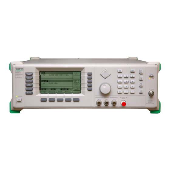
Chapter 1 General Information Table of Contents SCOPE OF MANUAL ....1-3 INTRODUCTION ....1-3 DESCRIPTION . - Page 11 Figure 1-1. Series 681XXB Synthesized Sweep Generator...
-
Page 12: Scope Of Manual
SCOPE OF MANUAL This manual provides general information, installation, and operating information for the WILTRON Series 681XXB Synthesized Sweep Gen- erator. (Throughout this manual, the terms 681XXB and sweep gener- ator will be used interchangeably to refer to the instrument.) Manual organization is shown in the table of contents. - Page 13 GENERAL 681XXB INFORMATION MODELS Table 1-1. Series 681XXB Models (1 of 2) 681XXB Frequency Output Power Output Power Model (GHz) w/Step Attenuator 68137B 2.0 – 20.0 GHz +13.0 dBm +11.0 dBm 68145B 0.5 – 20.0 GHz +13.0 dBm +11.0 dBm 68147B 0.01 –...
- Page 14 GENERAL 681XXB INFORMATION MODELS Table 1-1. Series 681XXB Models (2 of 2) 681XXB Frequency Output Power Output Power Model (GHz) w/Step Attenuator 0.01 – 2.0 GHz +12.0 dBm 2.0 – 20.0 GHz +10.0 dBm 68197B 20.0 – 40.0 GHz +2.5 dBm Not Available 40.0 –...
-
Page 15: Identification Number
Manual is 10370-10274. Maintenance The Maintenance Manual supplies service informa- Manual tion for all models in the 681XXB series. The service information includes functional circuit descriptions, block diagrams, performance verification tests, cali- bration procedures, troubleshooting data, and assem- bly and component removal/replacement procedures. -
Page 16: Options
Option 11, 0.1 Hz Frequency Resolution. Provides frequency resolution of 0.1 Hz. Option 14, WILTRON 360B VNA Compatibility. Modifies rack mounting hardware to mate unit in a WILTRON 360B VNA con- sole. Option 15A, High Power Output. Adds high-power RF compo- nents to the instrument providing increased RF output power in the 2–26.5 GHz frequency range. -
Page 17: Performance Specifications
GENERAL RECOMMENDED INFORMATION TEST EQUIPMENT PERFORMANCE Series 681XXB Synthesized Sweep Generator performance specifica- SPECIFICATIONS tions are provided in Appendix B. Table 1-2 lists the recommended test equipment for performing the Se- RECOMMENDED TEST EQUIPMENT ries 681XXB Synthesized Sweep Generator operation verification tests in Chapter 5. - Page 18 Chapter 2 Installation Table of Contents INTRODUCTION ....2-3 INITIAL INSPECTION ....2-3 PREPARATION FOR USE .
-
Page 19: Introduction
WIL- TRON Customer Service. If either the shipping container is damaged or the cushioning material shows signs of stress, notify the carrier as well as WILTRON. Keep the shipping materials for the carrier’s inspec- tion. 681XXB OM... -
Page 20: Preparation For Use
PREPARATION INSTALLATION FOR USE PREPARATION FOR USE Preparation for use consists of checking that the rear panel line volt- age selector switch is set for the correct line voltage and connecting the sweep generator to the power source. The following paragraphs provide these procedures along with information about power requirements, warmup times, and the operating environment. -
Page 21: Standby Operation
PREPARATION INSTALLATION FOR USE Line Fuse Line Voltage Selector Switch GPIB Connector Figure 2-1. Sweep Generator Rear Panel showing Power Connection Standby Op- Whenever the sweep generator is not being used it eration should be left connected to the power source and LEVEL placed in standby. -
Page 22: Warmup Time
PREPARATION INSTALLATION FOR USE Warmup From a cold start (ac power application), the sweep Time generator requires approximately 120 hours (5 days) –8 of warm up to achieve 2 x 10 /day frequency accu- racy and stability. If the Option 16 time base is installed, the 681XXB requires approximately 72 hours (3 days) of warm –10 up to achieve 5 x 10... -
Page 23: Gpib Setup And Interconnection
This interconnection is via a standard GPIB cable. The WILTRON Part number for such a cable is 2000-1, -2, or -4 (1, 2, or 4 meters in length). Setting the The default GPIB address is 5. - Page 24 GPIB SETUP AND INSTALLATION INTERCONNECTION Now press the menu soft-key Config . The System Configuration Menu (below) is displayed. To go to the Configure GPIB menu from this menu, press the menu soft-key GPIB . The Configure GPIB Menu (below) is displayed. Press the menu soft-key GPIB Address to change the current GPIB address of the sweep generator.
-
Page 25: Selecting The Line Terminator
GPIB SETUP AND INSTALLATION INTERCONNECTION Selecting Data is delimited on the GPIB by either the carriage the Line return (CR) ASCII character or both the carriage re- Terminator turn and line feed (CR/LF) ASCII characters. Which character is used depends upon the requirements of the system controller. -
Page 26: Preparation For Storage/Shipment
Seal the carton by using either shipping tape or an industrial stapler. Address the Container. If the instrument is being returned to WILTRON for service, mark the address of the appropriate WIL- TRON service center (Table 2-1) and your return ad- dress on the carton in one or more prominent locations. - Page 27 WILTRON INSTALLATION SERVICE CENTERS Table 2-1. WILTRON Service Centers UNITED STATES CHINA JAPAN WILTRON COMPANY WILTRON BEIJING SERVICE ANRITSU CORPORATION 490 Jarvis Drive CENTER 1800 Onna Atsugi-shi Morgan Hill, CA 95037-2809 416W Beijing Fortune Building Kanagawa-Prf. 243 Japan Telephone: (408) 778-2000...
- Page 28 Chapter 3 Local (Front Panel) Operation Table of Contents INTRODUCTION ....3-5 FRONT PANEL LAYOUT ....3-6 Line Key .
- Page 29 ENTERING DATA ....3-16 Opening the Parameter ....3-16 Editing the Current Value .
- Page 30 3-11 LEVELING OPERATIONS ... . . 3-48 Selecting a Leveling Mode ... . . 3-48 Attenuator Decoupling ....3-52 ALC Power Slope .
-
Page 31: Introduction
Chapter 3 Local (Front Panel) Operation INTRODUCTION This chapter provides information and instructions on operating the Series 681XXB Synthesized Sweep Generator using the front panel controls. It contains the following: Illustrations and diagrams of the front panel, data display area, and data entry area that identify and describe all front panel con- trols, inputs, and outputs. -
Page 32: Front Panel Layout
LOCAL (FRONT FRONT PANEL PANEL) OPERATION LAYOUT FRONT PANEL LAYOUT The 681XXB front panel is divided into two main areas—the data dis- play area and the data entry area. The following paragraphs provide a brief description of the front panel controls, inputs, outputs, and data display and data entry areas as shown in Figure 3-1. -
Page 33: Data
LOCAL (FRONT FRONT PANEL PANEL) OPERATION LAYOUT Data The data entry area consists of data entry keys and Entry Area controls that provide for (1) changing values for each 681XXB parameter, and (2) terminating the value entry and assigning the appropriate units (GHz, MHz, dBm, etc.). -
Page 34: Data Display Area
LOCAL (FRONT DATA DISPLAY PANEL) OPERATION AREA DATA DISPLAY AREA The data display area consists of the data display and the surrounding menu keys. The data display is a dot matrix liquid crystal display (LCD) that provides 16 lines of 40 characters each. Information is pre- sented on the LCD in the form of menu displays. -
Page 35: Menu Display Format
LOCAL (FRONT DATA DISPLAY PANEL) OPERATION AREA Menu The menu display is divided into specific areas that Display show the frequency, power level, and modulation in- Format formation for the current sweep generator setup. Menu labels for the current menu’s soft-keys appear along the bottom and right side of the display. -
Page 36: Menu Keys
LOCAL (FRONT DATA DISPLAY PANEL) OPERATION AREA Window Display A window display that overlays a portion of the cur- rent menu display is used to (1) show the parameter being edited; (2) display selection lists of preset fre- quencies, power levels, markers, etc.; (3) show the modulation and system configuration choices and current selections;... - Page 37 LOCAL (FRONT DATA DISPLAY PANEL) OPERATION AREA MODULATION—This menu provides you with access to sub-menus that let you select the type of signal modulation (AM, FM, or Square Wave) and control the option settings for each type. SYSTEM—This menu provides you with ac- cess to sub-menus that let you (1) reset the in- strument to factory-selected default values;...
-
Page 38: Data Entry Area
LOCAL (FRONT DATA ENTRY PANEL) OPERATION AREA DATA ENTRY AREA The value of a selected 681XXB parameter can be changed using the rotary data knob and/or keys of the data entry area. Each element of the data entry area is identified in Figure 3-3 and described in the fol- lowing paragraphs. - Page 39 LOCAL (FRONT DATA ENTRY PANEL) OPERATION AREA Rotary Data Knob The rotary data knob can be used to change the value of a parameter that is open for editing. The cursor is moved under the open parameter using the < and > pads of the cursor control key. Then, by slowly turning the knob clockwise or counter-clock- wise the value of the parameter is increased or de- creased by the unit size.
-
Page 40: Instrument Start-Up
LOCAL (FRONT INSTRUMENT PANEL) OPERATION START-UP INSTRUMENT START-UP Now that you have familiarized yourself with the layout of the sweep generator’s front panel controls and data display, you are ready to be- gin operating the instrument. Begin by powering it up. Powering Up Connect the 681XXB to an ac power source by fol- the 681XXB... -
Page 41: Self-Testing The 681Xxb
LOCAL (FRONT INSTRUMENT PANEL) OPERATION START-UP Self-Testing The 681XXB firmware includes internal diagnostics the 681XXB that self-test the instrument. These self-test diag- nostics perform a brief go/no-go test of most of the PCBs and other internal assemblies. If the sweep generator fails self-test, an error message is dis- played on the data display. - Page 42 LOCAL (FRONT RESET (DEFAULT) PANEL) OPERATION PARAMETERS Table 3-1. Reset (Default) Paramenters (1 of 2) 681XXB FREQUENCY PARAMETERS (GHz) MODEL M0 M1 M2 M3 M4 M5 M6 M7 M8 M9 ∆F NUMBER 68137B 3.5 2.0 20.0 2.0 5.0 8.0 11.0 14.0 17.0 20.0 3.5 2.0 20.0 2.0 5.0 8.0 11.0 14.0 17.0 20.0 1.0 68145B 3.5 2.2 20.0 2.0 5.0 8.0 11.0 14.0 17.0 20.0 3.5 2.0 20.0 2.0 5.0 8.0 11.0 14.0 17.0 20.0 1.0 68147B...
- Page 43 LOCAL (FRONT RESET (DEFAULT) PANEL) OPERATION PARAMETERS Table 3-1. Reset (Default) Paramenters (2 of 2) 681XXB POWER LEVEL PARAMETERS (dBm) MODEL NUMBER 68175B +1.0 –1.0 –2.0 –3.0 –4.0 –5.0 –6.0 –7.0 –8.0 68177B +1.0 –1.0 –2.0 –3.0 –4.0 –5.0 –6.0 –7.0 –8.0 68185B...
-
Page 44: Entering Data
LOCAL (FRONT ENTERING PANEL) OPERATION DATA ENTERING DATA Before proceeding to the various modes of sweep generator operation, you need to know how to enter data from the front panel. Entering data refers to changing a parameter’s value by editing its current value or entering a new value to replace the current value. -
Page 45: Editing The Current Value
LOCAL (FRONT ENTERING PANEL) OPERATION DATA Editing the To change the current value of a parameter by edit- Current ing, you can use either the cursor control key or the Value rotary data knob. Using the Cursor Control Key Cursor Using the <... -
Page 46: Entering A New Value
LOCAL (FRONT ENTERING PANEL) OPERATION DATA To close the open parameter when you are finished editing , press Edit F1 or make another menu selec- tion. Entering a To change the current value of a parameter by enter- New Value ing a new value for the parameter, use the data en- try keypad and termination keys. -
Page 47: Cw Frequency Operation
LOCAL (FRONT CW FREQUENCY PANEL) OPERATION OPERATION CW FREQUENCY One of the sweep generator’s major functions is to produce discrete OPERATION CW frequencies across the frequency range of the instrument. The fol- lowing paragraphs describe how to place the 681XXB in the CW fre- quency mode, select a CW frequency and power level for output, and activate the CW ramp. - Page 48 LOCAL (FRONT CW FREQUENCY PANEL) OPERATION OPERATION Selecting a Preset Frequency To select one of the preset frequencies for output, press the main menu key FREQUENCY CONTROL The CW Frequency Control menu (below) is dis- played. This menu lets you (1) select preset frequen- cies F0, F1, F2, M1, or M2 for output, (2) go to the frequency list menu, or (3) go to the tagged frequen- cies menu.
-
Page 49: Selecting A Power Level
LOCAL (FRONT CW FREQUENCY PANEL) OPERATION OPERATION Press Output Freq to output the selected frequency. This frequency is output until you select another fre- quency from the list and press Output Freq . On the frequency list, the output frequency selection is marked by a black square or, if tagged, an F high- lighted in reverse video. -
Page 50: Cw Ramp
LOCAL (FRONT CW FREQUENCY PANEL) OPERATION OPERATION NOTE You can also select any of the preset power levels or a power level sweep for a CW frequency. For instructions, refer to the Fixed Power Level Operation and Power Level Sweep Operation sections of this chapter. -
Page 51: Sweep Frequency Operation
LOCAL (FRONT SWEEP FREQUENCY PANEL) OPERATION OPERATION SWEEP FREQUENCY The sweep generator can generate broad (full range) and narrow band OPERATION sweeps across the frequency range of the instrument. The 681XXB has three sweep frequency modes—analog sweep, step sweep, and manual sweep. -
Page 52: Setting The Analog Sweep Time
LOCAL (FRONT SWEEP FREQUENCY PANEL) OPERATION OPERATION Setting the The duration of the analog sweep can be set for any Analog time in the range of 30 ms to 99 sec. The sweep time Sweep Time parameter is set from the sweep ramp menu. To go to the Analog Sweep Ramp menu (below) from the Analog Sweep menu, press Sweep Ramp . -
Page 53: Selecting A Sweep Trigger
LOCAL (FRONT SWEEP FREQUENCY PANEL) OPERATION OPERATION Selecting a The 681XXB provides sweep triggering for analog Sweep frequency sweep, step frequency sweep, and CW Trigger power sweep. The sweep generator has three modes of sweep triggering, each selectable from the trigger menu. -
Page 54: Selecting Step Sweep Mode
LOCAL (FRONT SWEEP FREQUENCY PANEL) OPERATION OPERATION Selecting In step sweep frequency mode, the output frequency Step Sweep changes in discrete, synthesized steps between se- Mode lected start and stop frequencies. Step sweeps can be from a high frequency to a low frequency and vice versa. -
Page 55: Setting Step Size And Dwell Time
LOCAL (FRONT SWEEP FREQUENCY PANEL) OPERATION OPERATION Setting Step There are two ways to set the size of each step of Size and the step sweep—set the step size or set the number Dwell Time of steps. The step size range is 1 kHz to the full fre- quency range of the sweep generator (0.1 Hz to full frequency range with Option 11);... -
Page 56: Selecting Manual Sweep Mode
LOCAL (FRONT SWEEP FREQUENCY PANEL) OPERATION OPERATION Selecting In manual sweep frequency mode, the output fre- Manual quency can be manually tuned in phase-locked Sweep Mode steps between the selected start and stop frequen- cies using the rotary data knob. As the knob is turned, the current output frequency is displayed on the data display as Fm. -
Page 57: Selecting A Sweep Range
LOCAL (FRONT SWEEP FREQUENCY PANEL) OPERATION OPERATION Selecting a Selecting a sweep range involves choosing a start Sweep Range and a stop frequency for the frequency sweep. The sweep range selection process is identical for all sweep frequency modes (analog, step, and manual). There are several ways you can select a sweep range, including: Editing the current start and stop frequency... - Page 58 LOCAL (FRONT SWEEP FREQUENCY PANEL) OPERATION OPERATION Selecting a Preset Sweep Range There are four preset sweep range parameters, se- lectable in the analog sweep, step sweep, and man- ual sweep frequency modes. The following is a description of each preset sweep range. F1-F2–provides a frequency sweep between the start frequency, F1, and the stop frequency, F3-F4–provides a frequency sweep between...
-
Page 59: Selecting A Power Level
LOCAL (FRONT SWEEP FREQUENCY PANEL) OPERATION OPERATION Setting a Preset Sweep Range–At the menu, se- lect the sweep range (F1-F2, F3-F4, F5-dF, or F6-dF) that you wish to set. The menu then displays the current frequency parameters for the selected sweep range. -
Page 60: Frequency Markers
LOCAL (FRONT SWEEP FREQUENCY PANEL) OPERATION OPERATION Frequency The sweep generator provides up to 20 independent, Markers pre-settable markers, F0-F9 and M0-M9, that can be used in the analog and step sweep frequency modes for precise frequency identification. Marker frequency accuracy is the same as sweep frequency accuracy. - Page 61 LOCAL (FRONT SWEEP FREQUENCY PANEL) OPERATION OPERATION Use the cursor control key to select a frequency pa- rameter from the marker list. The selected fre- quency parameter is highlighted in reverse video and displayed in full below the marker list. Editing a Marker List Frequency If you want to change a selected marker list fre- quency parameter’s value, press Edit to open the...
-
Page 62: Selecting Alternate Sweep Mode
LOCAL (FRONT SWEEP FREQUENCY PANEL) OPERATION OPERATION Selecting In alternate sweep frequency mode, the sweep gen- Alternate erator’s output frequency sweeps alternately be- Sweep Mode tween any two sweep ranges in analog sweep or any two sweep ranges in step sweep. The process of se- lecting and activating the alternate sweep is identi- cal for both analog and step sweep frequency modes. - Page 63 LOCAL (FRONT SWEEP FREQUENCY PANEL) OPERATION OPERATION Now, press Previous Menu to return to the Step Sweep Menu display (or the Analog Sweep Menu display if operating in analog sweep frequency mode). Notice the changes to the Step Sweep Menu display (below).
- Page 64 LOCAL (FRONT SWEEP FREQUENCY PANEL) OPERATION OPERATION When you are done selecting the alternate sweep range, press Previous Menu to return to the Alter- nate Sweep menu. Selecting an Alternate Sweep Power Level To go to the Alternate Level menu (below) from the Alternate Sweep menu, press Alt Level .
-
Page 65: Fixed Power Level Operation
LOCAL (FRONT FIXED POWER PANEL) OPERATION LEVEL OPERATION FIXED POWER LEVEL The sweep generator provides leveled output power over a maximum OPERATION range of up to 28 dB (up to 131 dB with Option 2) for CW and sweep frequency operations. Units with Option 15A provide leveled output power over a maximum range of up to 22 dB (up to 125 dB with Op- tion 2). - Page 66 LOCAL (FRONT FIXED POWER PANEL) OPERATION LEVEL OPERATION and appropriate terminator key. To close the open power level parameter, press Edit L1 or make an- other menu selection. Selecting a Preset Power Level To select one of the preset power levels for output, press the main menu key LEVEL CONTROL...
- Page 67 LOCAL (FRONT FIXED POWER PANEL) OPERATION LEVEL OPERATION Press Tag to mark a selected power level (place an L in front of it). If a power level is already tagged, pressing Tag will untag it (remove the L). Tagging selected power levels lets you quickly switch be- tween them using the scan keys of the Tagged Lev- els menu.
-
Page 68: Level Offset
LOCAL (FRONT FIXED POWER PANEL) OPERATION LEVEL OPERATION Level Offset Level offset lets you compensate for a device on the sweep generator’s output that alters the RF output power level at the point of interest. For example, the power level at the test device may be less or more than the displayed power level because of the loss through an external transmission line or the gain of an amplifier located between the 681XXB... -
Page 69: Power Level Sweep Operation
LOCAL (FRONT POWER LEVEL PANEL) OPERATION SWEEP OPERATION 3-10 POWER LEVEL The sweep generator provides leveled output power sweeps at CW fre- SWEEP OPERATION quencies and in conjunction with frequency sweeps (analog and step). Power level sweeps can be from a high level to a low level or vice versa. -
Page 70: And Dwell Time
LOCAL (FRONT POWER LEVEL PANEL) OPERATION SWEEP OPERATION Setting CW There are two ways to set the size of each step of Power Sweep the CW power sweep—set the step size or set the Step Size number of steps. The step size range is 0.01 dB to and Dwell the full power range of the synthesizer;... -
Page 71: Selecting A Cw Power Sweep Trigger
LOCAL (FRONT POWER LEVEL PANEL) OPERATION SWEEP OPERATION Selecting a There are three modes of triggering provided for the CW Power CW power sweep—automatic, external, and single. Sweep The sweep trigger is selectable from the CW Level Trigger Sweep Trigger menu. The following is a description of each trigger mode. -
Page 72: Selecting A Power Level Sweep Range
LOCAL (FRONT POWER LEVEL PANEL) OPERATION SWEEP OPERATION Selecting a Selecting a power level sweep range consists of Power Level choosing a start and stop level for the power level Sweep Range sweep. The power level sweep range selection proc- ess is identical for all power level sweep modes—... - Page 73 LOCAL (FRONT POWER LEVEL PANEL) OPERATION SWEEP OPERATION Selecting a Preset Power Level Sweep Range There are five preset power level sweep range pa- rameters selectable in the power level sweep modes. These preset power level sweep range parameters are L1-L2, L3-L4, L5-L6, L7-L8, and L9-L0. To select one of the preset power level sweep ranges from a Level Sweep menu, press the main menu key LEVEL...
-
Page 74: Selecting A Sweep Frequency / Step Power Mode
LOCAL (FRONT POWER LEVEL PANEL) OPERATION SWEEP OPERATION Selecting a In analog sweep frequency/step power mode or step Sweep Fre- sweep frequency/step power mode, a power level quency / Step step occurs after each frequency sweep. The power Power Mode level remains constant for the length of time re- quired to complete each frequency sweep. -
Page 75: Setting Power Level Step Size
LOCAL (FRONT POWER LEVEL PANEL) OPERATION SWEEP OPERATION Setting There are two ways to set the step size of the power Power Level level step that occurs after each frequency sweep– Step Size set the step size or set the number of steps. The step size range is 0.01 dB to the full power range of the synthesizer;... -
Page 76: Leveling Operations
LOCAL (FRONT LEVELING PANEL) OPERATION OPERATIONS 3-11 LEVELING The 681XXB generates leveled output power over a maximum range OPERATIONS of up to 28 dB (up to 131 dB with Option 2). Instruments with Option 15A provide leveled output power over a maximum range of up to 22 dB (up to 125 dB with Option 2). - Page 77 LOCAL (FRONT LEVELING PANEL) OPERATION OPERATIONS The ALC Mode menu lets you perform the following: Go to the leveling menu (select the ALC mode of operation). Go to the attenuation menu (decouple the at- tenuator, if equipped, from the ALC system and set the power level and attenuation).
- Page 78 LOCAL (FRONT LEVELING PANEL) OPERATION OPERATIONS Before going to the Leveling Menu from the ALC Mode menu, select whether the external ALC signal is to be connected to the front- or rear-panel EXT ALC IN connector. At the ALC Mode menu, press Ext ALC Front to se- lect front panel input, or Ext ALC Rear to select rear panel input.
- Page 79 LOCAL (FRONT LEVELING PANEL) OPERATION OPERATIONS At the Leveling menu, pressing either Internal or Fixed Gain will turn off external leveling. Press Previous Menu to return to the ALC Mode menu. Fixed Gain In the fixed gain mode, the ALC is disabled. The RF Level DAC and step attenuator (if installed) are used to control the relative power level.
-
Page 80: Attenuator Decoupling
LOCAL (FRONT LEVELING PANEL) OPERATION OPERATIONS Attenuator In 681XXBs equipped with option 2 step attenu- Decoupling ators, the ALC and attenuator work in conjunction to provide leveled output power down to –120 dBm. In the normal (coupled) leveling mode, when the de- sired power level is set, the correct combination of ALC level and attenuator setting is determined by the instrument firmware. -
Page 81: Alc Power Slope
LOCAL (FRONT LEVELING PANEL) OPERATION OPERATIONS ALC Power The ALC power slope function lets you compensate Slope for system, cable, and waveguide variations due to changes in frequency, by linearly increasing or de- creasing power output as the frequency increases. As shown in the following illustration, the power slope function provides you with the ability to set both the power slope and the pivot point. - Page 82 LOCAL (FRONT LEVELING PANEL) OPERATION OPERATIONS Press Slope On/Off to activate the ALC power slope function. Press Edit Pivot to open the pivot point frequency parameter for editing. Edit the current frequency us- ing the cursor control key or rotary data knob or en- SLOPE ter a new value using the keypad and appropriate When Power Slope is selected ON,...
-
Page 83: User Cal (User Level Flatness Correction)
LOCAL (FRONT LEVELING PANEL) OPERATION OPERATIONS User Cal The User Cal (user level flatness correction) func- (User Level tion lets you calibrate out path variations with fre- Flatness quency that are caused by external switching, Correction) amplifiers, couplers, and cables in the test setup. This is done by means of an entered power-offset ta- ble from a GPIB power meter or calculated data. - Page 84 LOCAL (FRONT LEVELING PANEL) OPERATION OPERATIONS Equipment Setup To create a power-offset table for user level flatness correction, connect the equipment (shown in Figure 3-4) as follows: Step 1 Using a GPIB cable, connect the Power Meter to the 681XXB. Step 2 Calibrate the Power Meter with the Power Sensor.
- Page 85 LOCAL (FRONT LEVELING PANEL) OPERATION OPERATIONS At the Configure GPIB menu, press More to go to an additional Configure GPIB menu (below). Press Pwr Mtr Address to change the address of the power meter on the GPIB (the power meter’s de- fault address is 13).
- Page 86 LOCAL (FRONT LEVELING PANEL) OPERATION OPERATIONS Place the sweep generator in a fixed power level mode by pressing the main menu key LEVEL/ALC SELECT At the resulting menu display, press Level . The 681XXB is now in fixed (non-swept) power level mode.
- Page 87 LOCAL (FRONT LEVELING PANEL) OPERATION OPERATIONS STEPS termination key. (The number of points range is 2 to 801.) When you have finished setting the open number-of-points parameter, close it by pressing Edit Points again or by making another menu selection. Now, press Start Cal to begin automatically taking power level correction information at each fre- quency point.
- Page 88 LOCAL (FRONT LEVELING PANEL) OPERATION OPERATIONS Erasing the Power-Offset Tables from Memory The power-offset tables are stored in non-volatile memory. A master reset is required to erase the con- tents of the tables and reprogram them with default data. To perform a master reset, proceed as follows: NOTE Step 1 With the 681XXB in standby, press and...
-
Page 89: Signal Modulation
LOCAL (FRONT SIGNAL PANEL) OPERATION MODULATION 3-12 SIGNAL MODULATION The sweep generator provides AM, FM, and square wave modulation of the output signal. All modulation modes—AM, FM, and square wave—can be active simultaneously. The following paragraphs provide descriptions and operating instructions for each modulation mode. Use the Amplitude Modulation Mode, Frequency Modulation Mode, and Square Wave Modulation Mode menu maps (Chapter 4, Figures 4-10, 4-11, and 4-12) to follow the menu sequences. -
Page 90: Frequency Modulation Operating Modes
LOCAL (FRONT SIGNAL PANEL) OPERATION MODULATION Select the input connector (front panel or rear panel AM IN) that is connected to the external signal source. Press On / Off to turn AM on and off. Both the AM status display and AM modulation status area will reflect your selection. -
Page 91: Providing Frequency Modulation
LOCAL (FRONT SIGNAL PANEL) OPERATION MODULATION In Unlocked Wide mode, frequency modulation is ac- complished by applying the modulating signal to the main tuning coil of the YIG-tuned oscillator. Un- locked Wide FM mode allows maximum deviations of ±100 MHz for DC to 100 Hz rates. Providing To provide frequency modulation, first set up the ex- Frequency... - Page 92 LOCAL (FRONT SIGNAL PANEL) OPERATION MODULATION This menu contains an external FM status window that shows the current menu selections and the measured FM Deviation. (The FM deviation meas- urement function measures the voltage of the exter- nal modulation signal and calculates the peak frequency deviation.) This menu lets you perform the following: Turn FM on/off.
-
Page 93: Square Wave Modulation Operating Modes
LOCAL (FRONT SIGNAL PANEL) OPERATION MODULATION Square Wave The 681XXB provides square wave (pulse) modula- Modulation tion of the output signal using modulating signals Operating from either its internal square wave generator or an Modes external signal generator. The sweep generator’s internal square wave gener- ator outputs modulating signals of 400 Hz, 1 kHz, 7.8125 kHz, and 27.8 kHz. - Page 94 LOCAL (FRONT SIGNAL PANEL) OPERATION MODULATION Press On/Off to turn square wave modulation on and off. Both the Square Wave status display and the Square Wave modulation status area will reflect your selection. Press Internal/External to select the source of the modulating signal.
- Page 95 LOCAL (FRONT SIGNAL PANEL) OPERATION MODULATION External Source Input Connector Selection If you have selected External to use a modulating signal from an external source, then when you press More the menu (below) is displayed. Press Front/Rear to select the front or rear panel IN connector.
-
Page 96: System Configuration
LOCAL (FRONT SYSTEM PANEL) OPERATION CONFIGURATION 3-13 SYSTEM The system configuration function provides menus that let you set or CONFIGURATION select instrument configuration items; for example, display intensity, polarity of blanking and video marker outputs, RF on or off during re- trace or between steps, GPIB address and line terminator, and incre- ment sizes for frequency, power level, and time parameters. -
Page 97: Configuring The Front Panel
LOCAL (FRONT SYSTEM PANEL) OPERATION CONFIGURATION Configuring Configuring the front panel of the sweep generator the Front involves adjusting the intensity level of the data dis- Panel play for ease of viewing. To go to the Configure Front Panel menu from the System Configuration menu, press Front Panel . -
Page 98: Configuring The Rear Panel
LOCAL (FRONT SYSTEM PANEL) OPERATION CONFIGURATION Configuring Configuring the rear panel of the sweep generator the Rear consists of selecting the polarity of the retrace blank- Panel ing, bandswitch blanking, retrace penlift, and video marker outputs. To go to the Configure Rear Panel menu from the System Configuration menu, press Rear Panel . -
Page 99: Configuring The Rf
LOCAL (FRONT SYSTEM PANEL) OPERATION CONFIGURATION Configuring Configuring the RF of the 681XXB involves select- the RF ing the state of the RF during retrace, during fre- quency switching in CW and step modes, and at reset and selecting whether a sweep triggered by a single or external trigger should rest at the top or bottom of the sweep ramp. -
Page 100: Configuring The Gpib
SS MODE Press SS Mode to place the sweep generator in a When SS Mode is selected on, this source lock mode for operation with a WILTRON message is displayed (in the fre- Model 360B Vector Network Analyzer. (Refer to... - Page 101 LOCAL (FRONT SYSTEM PANEL) OPERATION CONFIGURATION Press More to go to the additional Configure GPIB menu. Press Previous Menu to return to the System Con- figuration menu. Additional Configure GPIB Menu When you press More the additional Configure GPIB menu (below) is displayed. This menu lets you perform the following: Select the model and GPIB address for the power meter that is used to create a user level...
-
Page 102: Setting Increment Sizes
LOCAL (FRONT SYSTEM PANEL) OPERATION CONFIGURATION Setting The Increment menu lets you set the incremental Increment size for editing frequency, power level, and time pa- Sizes rameters. When the increment mode is selected on, these parameter values will increase or decrease by the set amount each time the ∧... -
Page 103: Saving/Recalling Instrument Setups
LOCAL (FRONT SAVING/RECALLING PANEL) OPERATION INSTRUMENT SETUPS 3-14 SAVING/RECALLING The 681XXB offers the capability to store up to ten complete front INSTRUMENT SETUPS panel setups. The setups are numbered 0 through 9. The following paragraphs describe how to save and recall front panel setups. Saving Once you have decided that an instrument setup Setups... -
Page 104: Erasing Stored Setups
LOCAL (FRONT SAVING/RECALLING PANEL) OPERATION INSTRUMENT SETUPS Erasing The front panel setups are stored in non-volatile Stored memory. A master reset is required to erase the con- Setups tents of the setups and reprogram them with de- fault data. To perform a master reset, proceed as follows: NOTE Step 1 With the 681XXB in standby, press and... -
Page 105: Secure Operation
LOCAL (FRONT SECURE PANEL) OPERATION OPERATION 3-15 SECURE OPERATION The 681XXB can be operated in a secure mode of operation. In this se- cure mode, the display of all frequency, power level, and modulation parameters is disabled during both local (front panel) and remote (GPIB) operations. - Page 106 Chapter 4 Local Operation–Menu Maps Table of Contents INTRODUCTION ....4-3 MENU MAP DESCRIPTION ... . 4-3...
- Page 107 Chapter 4 Local Operation–Menu Maps INTRODUCTION This chapter provides menu maps that support the 681XXB front panel operating instructions found in Chapter 3. It includes menu maps for all of the frequency, power level, and modulation modes of op- eration. In addition, a menu map for system configuration is also pro- vided.
-
Page 108: Sample Menu Map
LOCAL OPERATION SAMPLE –MENU MAPS MENU MAP Main Menu Key Cursor A Main Typical Menu Soft-Key Points To The Menu Displayed Whenever (Indicates The Active Menu Display Functional Description The Menu Soft-Key Is Depressed Main Menu Key) CW/SWEEP Edit Current SELECT Frequency FREQUENCY... -
Page 109: Cw Frequency Mode Menu Map
LOCAL OPERATION –MENU MAPS FREQUENCY MODE CW/SWEEP Edit Current SELECT Frequency FREQUENCY Edit Highlighted CONTROL Frequency LEVEL/ALC SELECT Set Slave Edit Current DF Frequency Set Slave Frequency LEVEL CONTROL Power Level Offset in 360B VNA Mode Set Slave Main MODULATION Power Level Set Slave Power Level Set Slave Alternate... -
Page 110: Analog Sweep Frequency Mode Menu Map
LOCAL OPERATION ANALOG SWEEP –MENU MAPS FREQUENCY MODE CW/SWEEP Edit Start Frequency SELECT FREQUENCY Edit End Frequency CONTROL LEVEL/ALC Edit Current SELECT Edit Current Sweep Time LEVEL CONTROL Power Level On / Off MODULATION On / Off SYSTEM On / Off Triggers Single Sweep Edit Alt Sweep... -
Page 111: Step Sweep Frequency Mode Menu Map
LOCAL OPERATION STEP SWEEP –MENU MAPS FREQUENCY MODE CW/SWEEP Edit Start Frequency SELECT FREQUENCY Edit End Frequency CONTROL LEVEL/ALC Edit Current SELECT Edit Current Sweep Time LEVEL CONTROL Power Level On / Off MODULATION On / Off SYSTEM On / Off Edit Alt Sweep Start Frequency Edit Alt Sweep... -
Page 112: Manual Sweep Frequency Mode Menu Map
LOCAL OPERATION MANUAL SWEEP –MENU MAPS FREQUENCY MODE CW/SWEEP Edit Start Frequency SELECT FREQUENCY Edit End Frequency CONTROL LEVEL/ALC Edit Step Size SELECT LEVEL Edit Number of Steps CONTROL MODULATION SYSTEM CW/SWEEP Edit Start Frequency SELECT FREQUENCY Edit End Frequency CONTROL LEVEL/ALC SELECT... -
Page 113: Fixed Power Level Mode Menu Map
LOCAL OPERATION FIXED POWER –MENU MAPS LEVEL MODE CW/SWEEP Edit Current SELECT Power Level FREQUENCY CONTROL LEVEL/ALC SELECT Edit Power LEVEL Level Offset CONTROL MODULATION On/Off Level Offset SYSTEM * Display Showing Level Offset On Edit Current Tag/Untag Highlighted CW/SWEEP Power Level Power Level SELECT... - Page 114 LOCAL OPERATION CW POWER –MENU MAPS SWEEP MODE CW/SWEEP Edit Start Power Level SELECT FREQUENCY Edit End Power Level CONTROL Edit Dwell TIme LEVEL/ALC SELECT Edit Step Size LEVEL On/Off CONTROL Edit Number of Steps MODULATION On/Off SYSTEM On/Off CW/SWEEP Edit Start Power Level SELECT FREQUENCY...
-
Page 115: Sweep Frequency/Step Power Mode Menu Map
LOCAL OPERATION SWEEP FREQUENCY/ –MENU MAPS STEP POWER MODE CW/SWEEP Edit Start Power Level SELECT FREQUENCY Edit End Power Level CONTROL LEVEL/ALC SELECT LEVEL Edit Step Size CONTROL MODULATION Edit Number of Steps SYSTEM CW/SWEEP Edit Start Power Level SELECT FREQUENCY Edit End Power Level CONTROL... -
Page 116: Leveling Modes Menu Map
LOCAL OPERATION LEVELING –MENU MAPS MODES Selects Internal ALC (Default Mode) CW/SWEEP SELECT Selects External ALC FREQUENCY CONTROL (External Detector Input) Selects Front Panel LEVEL/ALC Selects External ALC SELECT External ALC Input Power Meter Input LEVEL CONTROL Selects Rear Panel Selects ALC Off External ALC Input MODULATION... -
Page 117: Amplitude Modulation Mode Menu Map
LOCAL OPERATION AMPLITUDE –MENU MAPS MODULATION MODE CW/SWEEP AM On /Off SELECT FREQUENCY Log AM (0-25dB/V) or CONTROL Linear AM (0-100%/V) LEVEL/ALC SELECT Edit AM Sensitivity or 50 LEVEL CONTROL Input Impedance MODULATION Front Panel Input or Rear Panel Input SYSTEM CW/SWEEP SELECT... -
Page 118: Frequency Modulation Mode Menu Map
LOCAL OPERATION FREQUENCY –MENU MAPS MODULATION MODE CW/SWEEP FM On /Off SELECT FREQUENCY Edit FM Sensitivity CONTROL or 50 LEVEL/ALC SELECT Input Impedance LEVEL Front Panel Input or CONTROL Rear Panel Input Select Locked FM Mode MODULATION Selects Unlocked / Narrow SYSTEM FM Mode Selects Unlocked / Wide... -
Page 119: Square Wave Modulation Mode Menu Map
LOCAL OPERATION SQUARE WAVE –MENU MAPS MODULATION MODE Internal Square Wave Source Selected Square Wave CW/ S WEEP SELECT Modulation On/Off Internal Square Wave Source -or- F RE Q UE N CY CONT ROL External Square Wave Source LOW Level Triggers RF -or- LEVEL/ A LC SELECT HIGH Level Triggers RF... - Page 120 LOCAL OPERATION SYSTEM –MENU MAPS CONFIGURATION CW/SWEEP Brightens The Display SELECT FREQUENCY Dims The Display CONTROL LEVEL/ALC SELECT LEVEL CONTROL MODULATION SYSTEM Select +5V or -5V Level For Retrace and Bandswitch Blanking Select Normally Open or Closed Pen Lift Relay Contacts Select +5V or -5V level for Video Markers Select RF On or Off...
- Page 121 Chapter 5 Operation Verification Table of Contents INTRODUCTION ....5-3 TEST EQUIPMENT ....5-3 TEST RECORDS .
-
Page 122: Introduction
Chapter 5 Operation Verification INTRODUCTION This chapter contains three operation verification tests that can be used to verify Series 681XXB Synthesized Sweep Generator operation. Setup instructions and performance procedures are included for each test. The results can be compared with the specified limits that are shown on the test record forms that are provided for each test. -
Page 123: Initial 681Xxb Checkout
OPERATION INITIAL 681XXB VERIFICATION CHECKOUT tion test procedures and contain test information for all 681XXB mod- els. INITIAL 681XXB Before starting the operation verification tests in this chapter, perform CHECKOUT an initial checkout of the 681XXB to be tested. This initial checkout consists of applying power to the sweep generator, verifying that it passes self-test, and resetting it to the factory default parameters. -
Page 124: Cw Frequency Accuracy Test
OPERATION CW FREQUENCY VERIFICATION ACCURACY TEST CW FREQUENCY The following test verifies that the CW frequency output of the sweep ACCURACY TEST generator is within accuracy specifications. Table 5-2, beginning on page 5-7, contains test records that you can copy and use to record test results for this test. -
Page 125: Test Procedure
OPERATION CW FREQUENCY VERIFICATION ACCURACY TEST Test The following procedure tests both the coarse and Procedure fine loops to verify the accuracy of the CW frequency output. Step 1 Set up the 681XXB as follows: a. Reset the instrument by pressing SYSTEM , then RESET . - Page 126 OPERATION CW FREQUENCY VERIFICATION ACCURACY TEST Table 5-2A. CW Frequency Accuracy Test Record (for Standard Models) (1 of 3) Model 681 _ _ B Serial No. ____________________ Date ___________ 68137B / 68145B / 68147B 68153B / 68155B / 68159B 2.000 000 000* _____________________ 2.000 000 000* _____________________...
- Page 127 OPERATION CW FREQUENCY VERIFICATION ACCURACY TEST Table 5-2A. CW Frequency Accuracy Test Record (for Standard Models) (2 of 3) Model 681 _ _ B Serial No. ____________________ Date ___________ 68163B / 68165B / 68169B 68175B / 68177B 2.000 000 000* _____________________ 2.000 000 000* _____________________...
- Page 128 OPERATION CW FREQUENCY VERIFICATION ACCURACY TEST Table 5-2A. CW Frequency Accuracy Test Record (for Standard Models) (3 of 3) Model 681 _ _ B Serial No. ____________________ Date ___________ 68185B / 68187B 68195B / 68197B 2.000 000 000* _____________________ 2.000 000 000* _____________________ 6.000 000 000 _____________________...
- Page 129 OPERATION CW FREQUENCY VERIFICATION ACCURACY TEST Table 5-2B. CW Frequency Accuracy Test Record (for Models with Option 11) (1 of 3) Model 681 _ _ B Serial No. ____________________ Date ___________ 68137B / 68145B / 68147B 68153B / 68155B / 68159B 2.000 000 000 0* _____________________ 2.000 000 000 0*...
- Page 130 OPERATION CW FREQUENCY VERIFICATION ACCURACY TEST Figure 5-2B. CW Frequency Accuracy Test Record (for Models with Option 11) (2 of 3) Model 681 _ _ B Serial No. ____________________ Date ___________ 68163B / 68165B / 68169B 68175B / 68177B 2.000 000 000 0* _____________________ 2.000 000 000 0* _____________________...
- Page 131 OPERATION CW FREQUENCY VERIFICATION ACCURACY TEST Table 5-2B. CW Frequency Accuracy Test Record (for Models with Option 11) (3 of 3) Model 681 _ _ B Serial No. ____________________ Date ___________ 68185B / 68187B 68195B / 68197B 2,000 000 000 0* _____________________ 2,000 000 000 0* _____________________...
-
Page 132: Power Level Accuracy And Flatness Tests
OPERATION POWER LEVEL ACCURACY VERIFICATION AND FLATNESS TESTS POWER LEVEL These tests verify that the power level accuracy and flatness of the ACCURACY AND 681XXB meet specifications. Table 5-3, beginning on page 5-19, con- FLATNESS TESTS tains test records that you can copy and use to record test results for these tests. -
Page 133: Power Level Accuracy Test Procedure
OPERATION POWER LEVEL ACCURACY VERIFICATION AND FLATNESS TESTS Power Level Power level accuracy is checked by stepping the Accuracy power down in 1 dB increments from its maximum Test Proce- rated power level. dure Step 1 Set up the 681XXB as follows: a. -
Page 134: Power Level Flatness Test Procedure
OPERATION POWER LEVEL ACCURACY VERIFICATION AND FLATNESS TESTS Power Level Power level flatness is checked by measuring the Flatness Test power level variation during a full band sweep; first Procedure in the step sweep mode, then in the analog sweep mode. - Page 135 OPERATION POWER LEVEL ACCURACY VERIFICATION AND FLATNESS TESTS g. Now, return to the Step Sweep menu by pressing the main menu key CW/SWEEP SELECT h. At the Step Sweep menu, press Sweep Ramp to go to the Step Sweep Ramp menu (below). i.
- Page 136 OPERATION POWER LEVEL ACCURACY VERIFICATION AND FLATNESS TESTS Step 3 Set up the 681XXB as follows for an ana- log sweep power level flatness test: a. Reset the instrument by pressing , then Reset . The CW SYSTEM Menu is displayed. b.
- Page 137 OPERATION POWER LEVEL ACCURACY VERIFICATION AND FLATNESS TESTS h. At the Analog Sweep menu, press the menu soft-key Sweep Ramp to go to the Analog Sweep Ramp menu. i. Press Sweep Time to open the sweep time parameter for editing. j.
- Page 138 OPERATION POWER LEVEL ACCURACY VERIFICATION AND FLATNESS TESTS Table 5-3. Power Level Accuracy and Flatness Test Record (1 of 46) Model 68137B Serial No. ____________________ Date ___________ Model 68137B (without Option 2A Step Attenuator) Power Level Accuracy * (CW Frequency = 5.0 GHz) Set Power Measured Power +13 dBm...
- Page 139 OPERATION POWER LEVEL ACCURACY VERIFICATION AND FLATNESS TESTS Table 5-3. Power Level Accuracy and Flatness Test Record (2 of 46) Model 68137B Serial No. ____________________ Date ___________ Model 68137B (with Option 2A Step Attenuator) Power Level Accuracy * (CW Frequency = 5.0 GHz) Set Power Measured Power +11 dBm...
- Page 140 OPERATION POWER LEVEL ACCURACY VERIFICATION AND FLATNESS TESTS Table 5-3. Power Level Accuracy and Flatness Test Record (3 of 46) Model 68137B w/Option 15A Serial No. ____________________ Date ___________ Model 68137B with Option 15A High Power (without Option 2A Step Attenuator) Power Level Accuracy * (CW Frequency = 5.0 GHz) Set Power...
- Page 141 OPERATION POWER LEVEL ACCURACY VERIFICATION AND FLATNESS TESTS Table 5-3. Power Level Accuracy and Flatness Test Record (4 of 46) Model 68137B w/Option 15A Serial No. ____________________ Date ___________ Model 68137B with Option 15A High Power (with Option 2A Step Attenuator) Power Level Accuracy * (CW Frequency = 5.0 GHz) Set Power...
- Page 142 OPERATION POWER LEVEL ACCURACY VERIFICATION AND FLATNESS TESTS Table 5-3. Power Level Accuracy and Flatness Test Record (5 of 46) Model 68145B Serial No. ____________________ Date ___________ Model 68145B (without Option 2A Step Attenuator) Power Level Accuracy * Power Level Accuracy * (CW Frequency = 1.0 GHz) (CW Frequency = 5.0 GHz) Set Power...
- Page 143 OPERATION POWER LEVEL ACCURACY VERIFICATION AND FLATNESS TESTS Table 5-3. Power Level Accuracy and Flatness Test Record (6 of 46) Model 68145B Serial No. ____________________ Date ___________ Model 68145B (with Option 2A Step Attenuator) Power Level Accuracy * Power Level Accuracy * (CW Frequency = 1.0 GHz) (CW Frequency = 5.0 GHz) Set Power...
- Page 144 OPERATION POWER LEVEL ACCURACY VERIFICATION AND FLATNESS TESTS Table 5-3. Power Level Accuracy and Flatness Test Record (7 of 46) Model 68145B w/Option 15A Serial No. ____________________ Date ___________ Model 68145B with Option 15A High Power (without Option 2A Step Attenuator) Power Level Accuracy * Power Level Accuracy * (CW Frequency = 1.0 GHz)
- Page 145 OPERATION POWER LEVEL ACCURACY VERIFICATION AND FLATNESS TESTS Table 5-3. Power Level Accuracy and Flatness Test Record (8 of 46) Model 68145B w/Option 15A Serial No. ____________________ Date ___________ Model 68145B with Option 15A High Power (with Option 2A Step Attenuator) Power Level Accuracy * Power Level Accuracy * (CW Frequency = 1.0 GHz)
- Page 146 OPERATION POWER LEVEL ACCURACY VERIFICATION AND FLATNESS TESTS Table 5-3. Power Level Accuracy and Flatness Test Record (9 of 46) Model 68147B Serial No. ____________________ Date ___________ Model 68147B (without Option 2A Step Attenuator) Power Level Accuracy * Power Level Accuracy * (CW Frequency = 1.0 GHz) (CW Frequency = 5.0 GHz) Set Power...
- Page 147 OPERATION POWER LEVEL ACCURACY VERIFICATION AND FLATNESS TESTS Table 5-3. Power Level Accuracy and Flatness Test Record (10 of 46) Model 68147B Serial No. ____________________ Date ___________ Model 68147B (with Option 2A Step Attenuator) Power Level Accuracy * Power Level Accuracy * (CW Frequency = 1.0 GHz) (CW Frequency = 5.0 GHz) Set Power...
- Page 148 OPERATION POWER LEVEL ACCURACY VERIFICATION AND FLATNESS TESTS Table 5-3. Power Level Accuracy and Flatness Test Record (11 of 46) Model 68147B w/Option 15A Serial No. ____________________ Date ___________ Model 68147B with Option 15A High Power (without Option 2A Step Attenuator) Power Level Accuracy * Power Level Accuracy * (CW Frequency = 1.0 GHz)
- Page 149 OPERATION POWER LEVEL ACCURACY VERIFICATION AND FLATNESS TESTS Table 5-3. Power Level Accuracy and Flatness Test Record (12 of 46) Model 68147B w/Option 15A Serial No. ____________________ Date ___________ Model 68147B with Option 15A High Power (with Option 2A Step Attenuator) Power Level Accuracy * Power Level Accuracy * (CW Frequency = 1.0 GHz)
- Page 150 OPERATION POWER LEVEL ACCURACY VERIFICATION AND FLATNESS TESTS Table 5-3. Power Level Accuracy and Flatness Test Record (13 of 46) Model 68153B Serial No. ____________________ Date ___________ Model 68153B (without Option 2A Step Attenuator) Power Level Accuracy * Power Level Accuracy * (CW Frequency = 5.0 GHz) (CW Frequency = 22.0 GHz) Set Power...
- Page 151 OPERATION POWER LEVEL ACCURACY VERIFICATION AND FLATNESS TESTS Table 5-3. Power Level Accuracy and Flatness Test Record (14 of 46) Model 68153B Serial No. ____________________ Date ___________ Model 68153B (with Option 2A Step Attenuator) Power Level Accuracy * Power Level Accuracy * (CW Frequency = 5.0 GHz) (CW Frequency = 22.0 GHz) Set Power...
- Page 152 OPERATION POWER LEVEL ACCURACY VERIFICATION AND FLATNESS TESTS Table 5-3. Power Level Accuracy and Flatness Test Record (15 of 46) Model 68153B w/Option 15A Serial No. ____________________ Date ___________ Model 68153B with Option 15A High Power (without Option 2A Step Attenuator) Power Level Accuracy * Power Level Accuracy * (CW Frequency = 5.0 GHz)
- Page 153 OPERATION POWER LEVEL ACCURACY VERIFICATION AND FLATNESS TESTS Table 5-3. Power Level Accuracy and Flatness Test Record (16 of 46) Model 68153B w/Option 15A Serial No. ____________________ Date ___________ Model 68153B with Option 15A High Power (with Option 2A Step Attenuator) Power Level Accuracy * Power Level Accuracy * (CW Frequency = 5.0 GHz)
- Page 154 OPERATION POWER LEVEL ACCURACY VERIFICATION AND FLATNESS TESTS Table 5-3. Power Level Accuracy and Flatness Test Record (17 of 46) Model 68155B Serial No. ____________________ Date ___________ Model 68155B (without Option 2A Step Attenuator) Power Level Accuracy * Power Level Accuracy * Power Level Accuracy * (CW Frequency = 1.0 GHz) (CW Frequency = 5.0 GHz)
- Page 155 OPERATION POWER LEVEL ACCURACY VERIFICATION AND FLATNESS TESTS Table 5-3. Power Level Accuracy and Flatness Test Record (18 of 46) Model 68155B Serial No. ____________________ Date ___________ Model 68155B (with Option 2A Step Attenuator) Power Level Accuracy * Power Level Accuracy * Power Level Accuracy * (CW Frequency = 1.0 GHz) (CW Frequency = 5.0 GHz)
- Page 156 OPERATION POWER LEVEL ACCURACY VERIFICATION AND FLATNESS TESTS Table 5-3. Power Level Accuracy and Flatness Test Record (19 of 46) Model 68155B w/Option 15A Serial No. ____________________ Date ___________ Model 68155B with Option 15A High Power (without Option 2A Step Attenuator) Power Level Accuracy * Power Level Accuracy * Power Level Accuracy *...
- Page 157 OPERATION POWER LEVEL ACCURACY VERIFICATION AND FLATNESS TESTS Table 5-3. Power Level Accuracy and Flatness Test Record (20 of 46) Model 68155B w/Option 15A Serial No. ____________________ Date ___________ Model 68155B with Option 15A High Power (with Option 2A Step Attenuator) Power Level Accuracy * Power Level Accuracy * Power Level Accuracy *...
- Page 158 OPERATION POWER LEVEL ACCURACY VERIFICATION AND FLATNESS TESTS Table 5-3. Power Level Accuracy and Flatness Test Record (21 of 46) Model 68159B Serial No. ____________________ Date ___________ Model 68159B (without Option 2A Step Attenuator) Power Level Accuracy * Power Level Accuracy * Power Level Accuracy * (CW Frequency = 1.0 GHz) (CW Frequency = 5.0 GHz)
- Page 159 OPERATION POWER LEVEL ACCURACY VERIFICATION AND FLATNESS TESTS Table 5-3. Power Level Accuracy and Flatness Test Record (22 of 46) Model 68159B Serial No. ____________________ Date ___________ Model 68159B (with Option 2A Step Attenuator) Power Level Accuracy * Power Level Accuracy * Power Level Accuracy * (CW Frequency = 1.0 GHz) (CW Frequency = 5.0 GHz)
- Page 160 OPERATION POWER LEVEL ACCURACY VERIFICATION AND FLATNESS TESTS Table 5-3. Power Level Accuracy and Flatness Test Record (23 of 46) Model 68159B w/Option 15A Serial No. ____________________ Date ___________ Model 68159B with Option 15A High Power (without Option 2A Step Attenuator) Power Level Accuracy * Power Level Accuracy * Power Level Accuracy *...
- Page 161 OPERATION POWER LEVEL ACCURACY VERIFICATION AND FLATNESS TESTS Table 5-3. Power Level Accuracy and Flatness Test Record (24 of 46) Model 68159B w/Option 15A Serial No. ____________________ Date ___________ Model 68159B with Option 15A High Power (with Option 2A Step Attenuator) Power Level Accuracy * Power Level Accuracy * Power Level Accuracy *...
- Page 162 OPERATION POWER LEVEL ACCURACY VERIFICATION AND FLATNESS TESTS Table 5-3. Power Level Accuracy and Flatness Test Record (25 of 46) Model 68163B Serial No. ____________________ Date ___________ Model 68163B (without Option 2B Step Attenuator) Power Level Accuracy * Power Level Accuracy * (CW Frequency = 5.0 GHz) (CW Frequency = 25.0 GHz) Set Power...
- Page 163 OPERATION POWER LEVEL ACCURACY VERIFICATION AND FLATNESS TESTS Table 5-3. Power Level Accuracy and Flatness Test Record (26 of 46) Model 68163B Serial No. ____________________ Date ___________ Model 68163B (with Option 2B Step Attenuator) Power Level Accuracy * Power Level Accuracy * (CW Frequency = 5.0 GHz) (CW Frequency = 25.0 GHz) Set Power...
- Page 164 OPERATION POWER LEVEL ACCURACY VERIFICATION AND FLATNESS TESTS Table 5-3. Power Level Accuracy and Flatness Test Record (27 of 46) Model 68163B w/Option 15A Serial No. ____________________ Date ___________ Model 68163B with Option 15A High Power (without Option 2B Step Attenuator) Power Level Accuracy * Power Level Accuracy * (CW Frequency = 5.0 GHz)
- Page 165 OPERATION POWER LEVEL ACCURACY VERIFICATION AND FLATNESS TESTS Table 5-3. Power Level Accuracy and Flatness Test Record (28 of 46) Model 68163B w/Option 15A Serial No. ____________________ Date ___________ Model 68163B with Option 15A High Power (with Option 2B Step Attenuator) Power Level Accuracy * Power Level Accuracy * (CW Frequency = 5.0 GHz)
- Page 166 OPERATION POWER LEVEL ACCURACY VERIFICATION AND FLATNESS TESTS Table 5-3. Power Level Accuracy and Flatness Test Record (29 of 46) Model 68165B Serial No. ____________________ Date ___________ Model 68165B (without Option 2B Step Attenuator) Power Level Accuracy * Power Level Accuracy * Power Level Accuracy * (CW Frequency = 1.0 GHz) (CW Frequency = 5.0 GHz)
- Page 167 OPERATION POWER LEVEL ACCURACY VERIFICATION AND FLATNESS TESTS Table 5-3. Power Level Accuracy and Flatness Test Record (30 of 46) Model 68165B Serial No. ____________________ Date ___________ Model 68165B (with Option 2B Step Attenuator) Power Level Accuracy * Power Level Accuracy * Power Level Accuracy * (CW Frequency = 1.0 GHz) (CW Frequency = 5.0 GHz)
- Page 168 OPERATION POWER LEVEL ACCURACY VERIFICATION AND FLATNESS TESTS Table 5-3. Power Level Accuracy and Flatness Test Record (31 of 46) Model 68165B w/Option 15A Serial No. ____________________ Date ___________ Model 68165B with Option 15A High Power (without Option 2B Step Attenuator) Power Level Accuracy * Power Level Accuracy * Power Level Accuracy *...
- Page 169 OPERATION POWER LEVEL ACCURACY VERIFICATION AND FLATNESS TESTS Table 5-3. Power Level Accuracy and Flatness Test Record (32 of 46) Model 68165B w/Option 15A Serial No. ____________________ Date ___________ Model 68165B with Option 15A High Power (with Option 2B Step Attenuator) Power Level Accuracy * Power Level Accuracy * Power Level Accuracy *...
- Page 170 OPERATION POWER LEVEL ACCURACY VERIFICATION AND FLATNESS TESTS Table 5-3. Power Level Accuracy and Flatness Test Record (33 of 46) Model 68169B Serial No. ____________________ Date ___________ Model 68169B (without Option 2B Step Attenuator) Power Level Accuracy * Power Level Accuracy * Power Level Accuracy * (CW Frequency = 1.0 GHz) (CW Frequency = 5.0 GHz)
- Page 171 OPERATION POWER LEVEL ACCURACY VERIFICATION AND FLATNESS TESTS Table 5-3. Power Level Accuracy and Flatness Test Record (34 of 46) Model 68169B Serial No. ____________________ Date ___________ Model 68169B (with Option 2B Step Attenuator) Power Level Accuracy * Power Level Accuracy * Power Level Accuracy * (CW Frequency = 1.0 GHz) (CW Frequency = 5.0 GHz)
- Page 172 OPERATION POWER LEVEL ACCURACY VERIFICATION AND FLATNESS TESTS Table 5-3. Power Level Accuracy and Flatness Test Record (35 of 46) Model 68169B w/Option 15A Serial No. ____________________ Date ___________ Model 68169B with Option 15A High Power (without Option 2B Step Attenuator) Power Level Accuracy * Power Level Accuracy * Power Level Accuracy *...
- Page 173 OPERATION POWER LEVEL ACCURACY VERIFICATION AND FLATNESS TESTS Table 5-3. Power Level Accuracy and Flatness Test Record (36 of 46) Model 68169B w/Option 15A Serial No. ____________________ Date ___________ Model 68169B with Option 15A High Power (with Option 2B Step Attenuator) Power Level Accuracy * Power Level Accuracy * Power Level Accuracy *...
- Page 174 OPERATION POWER LEVEL ACCURACY VERIFICATION AND FLATNESS TESTS Table 5-3. Power Level Accuracy and Flatness Test Record (37 of 46) Model 68175B Serial No. ____________________ Date ___________ Model 68175B (without Option 2C Step Attenuator) Power Level Accuracy * Power Level Accuracy * Power Level Accuracy * (CW Frequency = 5.0 GHz) (CW Frequency = 25.0 GHz)
- Page 175 OPERATION POWER LEVEL ACCURACY VERIFICATION AND FLATNESS TESTS Table 5-3. Power Level Accuracy and Flatness Test Record (38 of 46) Model 68175B Serial No. ____________________ Date ___________ Model 68175B (with Option 2C Step Attenuator) Power Level Accuracy * Power Level Accuracy * Power Level Accuracy * (CW Frequency = 5.0 GHz) (CW Frequency = 25.0 GHz)
- Page 176 OPERATION POWER LEVEL ACCURACY VERIFICATION AND FLATNESS TESTS Table 5-3. Power Level Accuracy and Flatness Test Record (39 of 46) Model 68177B Serial No. ____________________ Date ___________ Model 68177B (without Option 2C Step Attenuator) Power Level Accuracy * Power Level Accuracy * Power Level Accuracy * (CW Frequency = 5.0 GHz) (CW Frequency = 25.0 GHz)
- Page 177 OPERATION POWER LEVEL ACCURACY VERIFICATION AND FLATNESS TESTS Table 5-3. Power Level Accuracy and Flatness Test Record (40 of 46) Model 68177B Serial No. ____________________ Date ___________ Model 68177B (with Option 2C Step Attenuator) Power Level Accuracy * Power Level Accuracy * Power Level Accuracy * (CW Frequency = 5.0 GHz) (CW Frequency = 25.0 GHz)
- Page 178 OPERATION POWER LEVEL ACCURACY VERIFICATION AND FLATNESS TESTS Table 5-3. Power Level Accuracy and Flatness Test Record (41 of 46) Model 68185B Serial No. ____________________ Date ___________ Model 68185B (without Option 2D Step Attenuator) Power Level Accuracy * Power Level Accuracy * Power Level Accuracy * (CW Frequency = 5.0 GHz) (CW Frequency = 25.0 GHz)
- Page 179 OPERATION POWER LEVEL ACCURACY VERIFICATION AND FLATNESS TESTS Table 5-3. Power Level Accuracy and Flatness Test Record (42 of 46) Model 68185B Serial No. ____________________ Date ___________ Model 68185B (with Option 2D Step Attenuator) Power Level Accuracy * Power Level Accuracy * Power Level Accuracy * (CW Frequency = 5.0 GHz) (CW Frequency = 25.0 GHz)
- Page 180 OPERATION POWER LEVEL ACCURACY VERIFICATION AND FLATNESS TESTS Table 5-3. Power Level Accuracy and Flatness Test Record (43 of 46) Model 68187B Serial No. ____________________ Date ___________ Model 68187B (without Option 2D Step Attenuator) Power Level Accuracy * Power Level Accuracy * Power Level Accuracy * (CW Frequency = 5.0 GHz) (CW Frequency = 25.0 GHz)
- Page 181 OPERATION POWER LEVEL ACCURACY VERIFICATION AND FLATNESS TESTS Table 5-3. Power Level Accuracy and Flatness Test Record (44 of 46) Model 68187B Serial No. ____________________ Date ___________ Model 68187B (with Option 2D Step Attenuator) Power Level Accuracy * Power Level Accuracy * Power Level Accuracy * (CW Frequency = 5.0 GHz) (CW Frequency = 25.0 GHz)
- Page 182 OPERATION POWER LEVEL ACCURACY VERIFICATION AND FLATNESS TESTS Table 5-3. Power Level Accuracy and Flatness Test Record (45 of 46) Model 68195B Serial No. ____________________ Date ___________ Model 68195B Power Level Accuracy * Power Level Accuracy * Power Level Accuracy * (CW Frequency = 5.0 GHz) (CW Frequency = 25.0 GHz) (CW Frequency = 50.0 GHz)
- Page 183 OPERATION POWER LEVEL ACCURACY VERIFICATION AND FLATNESS TESTS Table 5-3. Power Level Accuracy and Flatness Test Record (46 of 46) Model 68197B Serial No. ____________________ Date ___________ Model 68197B Power Level Accuracy * Power Level Accuracy * Power Level Accuracy * (CW Frequency = 5.0 GHz) (CW Frequency = 25.0 GHz) (CW Frequency = 50.0 GHz)
- Page 184 Chapter 6 Operator Maintenance Table of Contents INTRODUCTION ....6-3 ERROR AND WARNING/STATUS MESSAGES . . 6-3 Self-Test Error Messages ....6-3 Normal Operation Error and Warning/Status Messages .
-
Page 185: Introduction
Chapter 6 Operator Maintenance INTRODUCTION This chapter provides the information necessary for operator mainte- nance of the sweep generator. Operator maintenance is limited to trou- bleshooting and repairs that can be made without removing the instru- ment covers. ERROR AND During normal operation, the 681XXB generates error messages to in- WARNING/STATUS dicate internal malfunctions, abnormal signal generator operations, or... - Page 186 OPERATOR ERROR AND WARNING/ MAINTENANCE STATUS MESSAGES WARNING Self-test error messages normally indicate the failure of an internal component or assembly of the CW generator. There are no operator serviceable components inside. Refer servic- ing of the instrument to qualified service technicians. To prevent the risk of electrical shock or damage to precision components, do not remove the equipment covers.
- Page 187 OPERATOR ERROR AND WARNING/ MAINTENANCE STATUS MESSAGES Table 6-1. Self-Test Error Messages (2 of 4) Error Message Description/Remarks Error 112 Indicates the coarse loop oscillator is not phase-locked. The 681XXB is still Coarse Loop Osc Failed operable but the accuracy and stability of the frequency outputs are greatly reduced.
- Page 188 OPERATOR ERROR AND WARNING/ MAINTENANCE STATUS MESSAGES Table 6-1. Self-Test Error Messages (3 of 4) Error Message Description/Remarks Error 126 Indicates a failure of the 2 to 8.4 GHz YIG-tuned oscillator. Do Not Attempt to 2 – 8.4 GHz Unlocked and Operate! Refer the instrument to a qualified service techician.
- Page 189 OPERATOR ERROR AND WARNING/ MAINTENANCE STATUS MESSAGES Table 6-1. Self-Test Error Messages (4 of 4) Error Message Description/Remarks Error 139 Indicates a failure in the 32 - 40 GHz switched doubler filter path within the SDM. 32 – 40 GHz SDM Section Failed The 681XXB is still operable but it will not produce an RF output in the 32 - 40 GHz frequency range.
- Page 190 OPERATOR ERROR AND WARNING/ MAINTENANCE STATUS MESSAGES Normal When an abnormal condition is detected during op- Operation eration, the 681XXB displays an error message to in- Error and dicate that the output is abnormal or that a signal Warning/ input or data entry is invalid. It also displays warn- Status ing messages to alert the operator to conditions that Messages...
- Page 191 OPERATOR ERROR AND WARNING/ MAINTENANCE STATUS MESSAGES Table 6-3. Possible Warning/Status Messages during Normal Operation Warning/Status Description Message This warning message indicates that the 100 MHz OVN COLD Crystal oven (or the 10 MHz Crystal oven if Option 16 is installed) has not reached operating temperature.
-
Page 192: Troubleshooting
OPERATOR MAINTENANCE TROUBLESHOOTING TROUBLESHOOTING Table 6-4 provides procedures for troubleshooting common malfunc- tions encountered during operation of the sweep generator. Included are procedures for troubleshooting faults that do not produce error mes- sages, such as, failure to power up and unexpected shutdown. Table 6-4. - Page 193 OPERATOR MAINTENANCE TROUBLESHOOTING Table 6-4. Troubleshooting (2 of 3) Sweep Generator Quits During Operation (OPERATE light remains on) Trouble Description: The sweep generator operates for some time, then shuts down (OPERATE light remains on). After a short period, the sweep generator resumes normal operation. This is an indication that the 681XXB has reached an excessive operating temperature.
- Page 194 OPERATOR MAINTENANCE TROUBLESHOOTING Table 6-4. Troubleshooting (3 of 3) UNLEVELED is Displayed Trouble Description: This message is displayed to indicate that the RF output is unleveled. Step 1 Check that the output power does not exceed the specified leveled-power rating and that the RF OUTPUT connector is terminated into a 50Ω...
-
Page 195: Routine Maintenance
OPERATOR ROUTINE MAINTENANCE MAINTENANCE ROUTINE MAINTENANCE Routine maintenance that can be performed by the operator consists of cleaning the fan filter, cleaning the data display, and replacing a defec- tive line fuse. Cleaning the The sweep generator must always receive adequate Fan Filter ventilation. - Page 196 OPERATOR ROUTINE MAINTENANCE MAINTENANCE Replacing The value of the line fuse used in the 681XXB is de- the Line Fuse termined by the line voltage selection—a 5A line fuse for 110 Vac line voltage; a 2.5A line fuse for 220 Vac line voltage. These line fuse values are printed on the rear panel next to the fuse holder.
- Page 197 OPERATOR ROUTINE MAINTENANCE MAINTENANCE Fuse Fuse Holder Figure 6-2. Replacing the Line Fuse 681XXB OM 6-15/6-16 Changed: November 1995...
- Page 198 Chapter 7 Use With Other Instruments Table of Contents INTRODUCTION ....7-3 MASTER-SLAVE OPERATION ... 7-4 Connecting the 68XXXBs .
-
Page 199: Introduction
It contains the following: Instructions for interconnecting and operating any two 68XXXBs in a master-slave configuration. Instructions for connecting the 681XXB to a WILTRON Model 562 Scalar Network Analyzer so that it can be used as a signal source for the analyzer. -
Page 200: Master-Slave Operation
“MASTER” to the rear panel AUX gether for Master-Slave operations, I/O connector on the Master 68XXXB. always use a WILTRON Master- Connect the AUX I/O cable labeled Slave interface cable set, Part No. “SLAVE” to the rear panel AUX I/O con- ND36329. -
Page 201: Initiating Master-Slave Operation
USE WITH MASTER-SLAVE OTHER INSTRUMENTS OPERATION to the appropriate connections on the DUT. Initiating The following paragraphs describe how to set up Master-Slave both 68XXXBs to perform master-slave operations. Operation Use the CW Frequency Mode menu map (Chapter 4, Figure 4-2) to follow the menu sequences. To initiate master-slave operation, turn on both 68XXXBs and place them in CW mode. - Page 202 USE WITH MASTER-SLAVE OTHER INSTRUMENTS OPERATION NOTE Upon reset, the slave frequencies (F0 - F9 and M0 - M9) return to the default values shown here. This menu lets you edit the listed frequencies for the Slave 68XXXB. Use the cursor control key to select a frequency pa- rameter from the list, then press Edit to edit its value.
-
Page 203: Master-Slave Operation In Vna Mode
USE WITH MASTER-SLAVE OTHER INSTRUMENTS OPERATION pad and appropriate termination key. When you have finished setting the open parameter, close it by pressing its menu soft-key or by making another menu selection. Press Enable to begin master-slave operation. Press CW to return to the CW menu. Master-Slave During master-slave operation, the Slave unit is in Operation... - Page 204 USE WITH MASTER-SLAVE OTHER INSTRUMENTS OPERATION Press VNA Menu to go to the VNA Menu display (below). This menu lets you set the frequency offset and out- put power level for the Slave 68XXXB in the VNA mode. Press VNA Offset to open the slave frequency off- set parameter.
-
Page 205: Terminating Master-Slave Operation
USE WITH MASTER-SLAVE OTHER INSTRUMENTS OPERATION Terminating The following describes how to terminate master- Master-Slave slave operation and return the Slave 68XXXB to lo- Operation cal (front panel) control. On the Master 68XXXB, select CW mode. At the CW Menu, press Master Slave to go to the Master Slave Menu display. -
Page 206: Use With A 562 Scalar Network Analyzer
USE WITH A 562 SCALAR OTHER INSTRUMENTS NETWORK ANALYZER USE WITH A 562 The 681XXB is directly compatible with the WILTRON Model 562 Sca- SCALAR NETWORK lar Network Analyzer (SNA). The following paragraphs provide in- ANALYZER structions for connecting the sweep generator to the 562 SNA so that is can be used as a signal source for the analyzer. - Page 207 USE WITH OPERATION WITH A 562 OTHER INSTRUMENTS SCALAR NETWORK ANALYZER 681XXB rear panel IEEE-488 GPIB con- nector. Step 3 Turn on the 681XXB and the 562. The system is now ready to operate. Using Discrete Cables Connect the 681XXB to the 562 SNA as follows: Step 1 Connect one end of a coaxial cable to the 681XXB rear panel HORIZ OUT connec-...
-
Page 208: Use With A 360B Vector Network Analyzer
USE WITH A 360B VECTOR OTHER INSTRUMENTS NETWORK ANALYZER USE WITH A 360B The 681XXB sweep generator is compatible with the WILTRON Model VECTOR NETWORK 360B Vector Network Analyzer (VNA). The following paragraphs pro- ANALYZER vide instructions for connecting the 681XXB to the 360B VNA and con- figuring the sweep generator so that it can operate as a signal source for the analyzer. -
Page 209: Modes Of Operation
USE WITH USE WITH A 360B VECTOR OTHER INSTRUMENTS NETWORK ANALYZER If the 681XXB contains an Option 16 high-stability time base, connect the coax- ial cable between the 681XXB rear panel 10 MHz REF OUT connector and the 360B rear panel 10 MHz REF IN connector. Step 3 Connect one end of a GPIB cable, 1 meter in length, to the 681XXB rear panel IEEE-... - Page 210 USE WITH USE WITH A 360B VECTOR OTHER INSTRUMENTS NETWORK ANALYZER At the System Configuration menu, press GPIB . The Configure GPIB Menu (below) is displayed. Verify that the GPIB address and terminator shown on the display match the System Bus source ad- dress and data terminator that are set on the 360B VNA.
-
Page 211: Tracking Mode
USE WITH USE WITH A 360B VECTOR OTHER INSTRUMENTS NETWORK ANALYZER Terminating 360B Source Lock Mode Opera- tions To terminate 360B VNA source lock mode opera- tions, you must first return the 681XXB to local con- trol and then turn off the SS Mode. To return the 681XXB to local control, turn off the 360B VNA. - Page 212 USE WITH USE WITH A 360B VECTOR OTHER INSTRUMENTS NETWORK ANALYZER If the address of the 681XXB on the System Bus needs changing, press GPIB Address . Enter the new address using the cursor control key or the data entry keypad and the terminator key ADRS The new GPIB address will appear on the display.
- Page 213 Appendix A Rear Panel Connectors INTRODUCTION This appendix provides descriptions for the rear panel connectors on a typical Series 681XXB Synthesized Sweep Generator. REAR PANEL Figure A-1 provides a illustration of the rear panel and describes the CONNECTORS rear panel connectors. Figures A-2 and A-3 provide pinout diagrams and descriptions for the CONNECTOR PINOUT DIAGRAMS...
- Page 214 0V erator (master-slave operation) and with other to 10V ramp. BNC connector, 50Ω impedance. WILTRON instruments such as the WILTRON 10 MHz REF IN: Accepts an external 10 MHz 562 Scalar Network Analyzer. A pinout diagram ±100 Hz, 0 to 10 dBm time-base signal.
- Page 215 REAR PANEL CONNECTORS FM IN: Accepts an external modulating signal DWELL IN: Accepts an external TTL low-level to produce FM on the RF output. FM sensitivity signal to stop the sweep in both analog- and step-sweep modes. The sweep resumes when and input impedance (50Ω...
- Page 216 REAR PANEL CONNECTOR CONNECTORS PINOUT DIAGRAMS AUX I/O SIGNAL NAME SIGNAL DESCRIPTION HORIZ OUTPUT Horizontal Sweep Output: Provides a 0V at beginning and +10V at end of sweep for all sweep modes, regardless of sweep width. In the CW mode, the voltage is proportional to frequency between 0V at low end and +10V at the high end of range.
- Page 217 REAR PANEL CONNECTOR CONNECTORS PINOUT DIAGRAMS SIGNAL NAME SIGNAL DESCRIPTION V/GHz Output: Provides a reference voltage relative to the RF output frequency V/GHz (1.0 V/GHz for Models 68137B, 68145B, and 68147B; 0.5 V/GHz for Models 68153B, 68155B, 68159B, 68163B, 68165B, and 68169B; 0.25V/GHz for Models 68175B, 68177B, 68185B, 68187B, 68195B, and 68197B).
- Page 218 REAR PANEL CONNECTOR CONNECTORS PINOUT DIAGRAMS IEEE-488 GPIB 13 14 15 16 17 18 19 20 21 22 23 24 9 10 11 12 SIGNAL NAME SIGNAL DESCRIPTION DIO 1 thru DIO 4 Data Input/Output: Bits are HIGH when the data is logical 0 and LOW when the data is logical 1.
- Page 219 Resolution: 360B VNA SOURCE LOCK MODE 1 kHz (0.1 Hz with Option 11) Under control of the WILTRON 360B Vector Network Ana- External 10 MHz Reference Input: Ac c e pt s ex tern al lyzer, the synthesized sweep generator is phase-locked at a 10 MHz ±100 Hz, 0 to +10 dBm time base signal.
- Page 220 PERFORMANCE SPECIFICATIONS PROGRAMMABLE FREQUENCY AGILITY Harmonic and Harmonic Related (Models having a high- Under GPIB control, up to 1000 non-sequential frequencies end frequency of >40 GHz and units with Option 15A at can be stored and then addressed as a phase-locked step maximum specified leveled output power): sweep.
- Page 221 PERFORMANCE SPECIFICATIONS POWER LINE and FAN ROTATION SPURIOUS AM Noise Floor: EMISSIONS (dBc) Typically <–145 dBm/Hz at 0 dBm output and offsets >5 MHz from carrier. Frequency Offset From Carrier Range RF OUTPUT (GHz) <300 Hz 300Hz to 1 kHz >1 kHz Power level specifications apply at 25 °...
- Page 222 PERFORMANCE SPECIFICATIONS MAXIMUM LEVELED OUTPUT POWER (Continued) UNLEVELED OUTPUT POWER RANGE (typical) Without an Attenuator: >40 dB below max power. Output Power With an Attenuator: >130 dB below max power. Frequency Output Model with Step Range Power Number Attenuator POWER LEVEL SWITCHING TIME (to within specified (GHz) (dBm) (dBm)
- Page 223 PERFORMANCE SPECIFICATIONS OTHER OUTPUT POWER SPECIFICATIONS SWEEP FREQUENCY/STEP POWER Output Power Resolution: 0.01 dB A power level step occurs after each frequency sweep. Source Impedance: 50Ω nomimal Power level remains constant for the length of time required Source SWR (Internal Leveling): to complete each sweep.
- Page 224 Emulations: The instrument responds to the published Supported power meters are Anritsu ML4803A and HP 437B, GPIB commands and responses of the WILTRON Models 438A, and 70100A. Five user tables are available with up to 6600, 6700, and 6XX00-series signal sources. When emu- 801 points/table.
- Page 225 PERFORMANCE SPECIFICATIONS Warm Up Time (Standard Time Base): INPUTS and OUTPUTS From Standby: 30 minutes. –8 From Cold Start (0°C): 120 hours to achieve <2 x 10 Input/Output Connectors per day frequency stability. Warm Up Time (Option 16 Time Base): Nomenclature Type Location...
- Page 226 Option 14, WILTRON 360B VNA Compatibility: Modifies V/GHz OUT: Provides a reference voltage relative to the RF rack mounting hardware to mate unit in a WILTRON 360B output frequency (refer to the table below). VNA console.
Need help?
Do you have a question about the 681XXB Series and is the answer not in the manual?
Questions and answers