Advertisement
Quick Links
Advertisement

Related Manuals for Vimar ELVOX 945B


Summary of Contents for Vimar ELVOX 945B
- Page 1 Installer guide 945B, 945B/I Porter’s Switchboard...
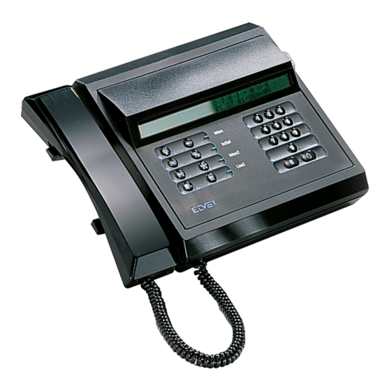
- Page 2 DESCRIPTION Porter's switchboard in desk-top version with black thermoplastic housing. This switchboard can call up to 99999999 users using a 20-key keypad which serves to enter user numbers, make calls, activate intercom or conference functions (excluding the building complex), release the door lock and for F1-F2 functions and to cancel the operation currently in progress. The switchboard can store up to 30 different calls (displayed by using the memory scroll button) and is provided with watch (with time and date) and two wake up functions.
- Page 3 STORED CALLS - Possibility of storing different types of "events": calls from interphones, activation of: different functions, door lock release, calls from switchboard. The selection of the type of events to store is managed by interactive menu type display (see "OPE- RATION OF MENU PROGRAMMING"...
- Page 4 PROGRAMMING THE SWITCHBOARD PARAMETERS The switchboard is delivered with an "already inserted" basic program , which can be modified according to the instructions to follow. The programming is necessary if the pre-programmed parameters do not satisfy the installation requirements. A) Entry to programming mode using the front switchboard keypad Press push-buttons "R"...
-
Page 5: Operation
OPERATION DISPLAYING THE TIME - DATE - WAKE UP TIME-TABLE The time is always displayed at the top on the right hand side of display. To display other data press push-buttons R+2 (or R+Number transf. [8->8]), and the following message will appear: DATE: 14/02 15:30:35 AL.RING: 12:30 &... - Page 6 PROGRAMMING MENU In the switchboard it is possible to program a series of accessory functions, such as: - TIME AND DATE - 2 WAKE-UP SERVICES - THE TYPE OF COMMAND YOU WANT TO MEMORIZE IN THE RECEPTION BUFFER (AND SIGNAL IT WITH A MELODY) - THE TYPE OF COMMAND YOU WANT TO SEND TO THE PRINTER (OPTIONAL).
- Page 7 PRINTING ACTIVATION By means of a lodge switchboard it is possible to print (with the reception time) all incoming calls, and possibly also the acti- vations of functions F1, F2, lock release and calls made by the same switchboard. 1) To carry out the printing you must have, besides the printer with parallel cable, a proper interface Art. 945/I (installed on the base of the same switchboard).
- Page 8 In memory there are 5 different melodies (numbered from 1 to 5) associated to different types of events. Their time dwell is variable according to the maximum number of tones (25,15,15,12,10 respectively). NOTE: a the present: 1 pink-panter, 2=Chopin, 3=Vivaldi, 4=Elelnco note (List of notes), 5= Happy-Birth.) We follow with the association between events and melodies (numbers from 1 to 5).
-
Page 9: Description Of Keypad
DESCRIPTION OF SWITCHBOARD KEYPAD The switchboard is equipped with a 20-key keypad divided into two sections: the right hand section is used to make calls, program the switchboard and cancel operations currently in progress. The left hand zone is instead used to activate porter’s call, door lock release, intercom, conference, call transfer to internal unit and notification functions. - Page 10 OPERATION OF SWITCHBOARD Introduction Switchboard Art. 945B can operate in two modes: internal and external mode. To select the mode required use INTER- NAL/EXTERNAL key to select EXTERNAL mode or INTERNAL mode. The lamp "EXTERNAL" indicates the status of the swit- chboard (lamp "on"...
- Page 11 - Call from user to switchboard: users can use the door lock release button on the interphone or monitor to call the switch- board. The number of the internal unit which has made the call is displayed on the LCD screen. If the switchboard is set to INTERNAL mode, the call is also accompanied by an acoustic signal.
- Page 12 ADJUSTMENTS AND DESCRIPTION OF TERMINALS Adjustment trimmers The following trimmers are fitted on the back of the switchboard: Adjusts the digital signal current generator (d.c. value 25 mA must not be changed unless otherwise specified). Adjusts the volume of the switchboard acoustic call signal. LCD contrast.
- Page 13 MINIMUM CONDUCTOR SECTION (mm Conductors Ø up to 50 m. Ø up to 100 m. Ø up to 200 m. 0,75 mm 1 mm 1,5 mm + - and lock 1 mm 1,5 mm 2,5 mm Others 0,5 mm 0,75 mm 1 mm Video Coaxial cable 75 Ohm (RG59 or...
- Page 14 SIMPLE RESIDENTIAL INSTALLATION WITH PORTER’S SWITCHBOARD Ref. diagram si091 INTERPHONE CABLE RISER POWER LINE Interc In/Out Interc2 Line2 Mains Switchboard Power supply Art. 945B Art. 6941 H CH S F1 5 R+ 88888888 C- Entrance panel with push-button Art. 8843 - 1283 C0- Entrance panel with keypad and display Art.
- Page 15 RESIDENTIAL INTERPHONE INSTALLATION WITH ONE MAIN PANEL, PORTER’S SWIT- CHBOARD AND TWO OR MORE STAIRWAY PANELS (BUILDING COMPLEX). Ref. diagram si094 INTERPHONE INTERPHONE CABLE RISER CABLE RISER Mains Mains Power supply Power supply Art. 6941 Art. 6941 CH S F1 S1 15 0 6 8 4 Cable riser...
- Page 16 MONITOR CABLE RISER WITH UNITS EQUIPPED WITH INTERNAL DIGITAL SIGNAL DECODING. Ref. diagram si356 MONITOR CABLE RISER 75ohm Monitor 75ohm Art. 6304 Art. 6304/C Art. 6504 Monitor Art. 6324 Art. 6624 Art. 6324/C Art. 6724 Art. 6344 Art. 662D Art. 6354 Art.
- Page 17 MONITOR RISER WITH FLOOR DISTRIBUTOR ART. 949B Ref. diagram si036 MONITOR CABLE RISER 75 ohm 75ohm Monitor Monitor Art. 6307 Art. 6627 Art. 6507 Art. 662B Art. 6307/C Art. 6727 Art. 6327 Art. 6527/C Monitor Monitor Monitor Monitor Art. 6023 + Art.
- Page 18 SIMPLE RESIDENTIAL INSTALLATION WITH PORTER’S SWITCHBOARD Ref. diagram si215 MONITOR CABLE RISER POWER LINE Interc In/Out Interc2 Line2 Mains Mains 3 4 5 6 7 aa a bb b Power supply Power supply Switchboard Art. 6948 Art. 945B Art. 6942 F2 3C 4 I+ I CH S F1 F2 3 4 5 +...
- Page 19 RESIDENTIAL VIDEO ENTRY INSTALLATION WITH ONE MAIN PANEL, PORTER’S SWIT- CHBOARD AND TWO OR MORE STAIRWAY PANELS (BUILDING COMPLEX). Ref. diagram si317 MONITOR MONITOR CABLE RISER CABLE RISER Mains Mains Power supply Power supply Art. 6948 Art. 6948 M2 V2 V1 M1 M2 V2 V1 M1 75 Ohm Cable riser...
- Page 20 BASIC DIAGRAM VERSIONS VERSION 1A Supplementary function F1-F2 connections in installations with interphones without internal decoding. INTERPHONE CABLE RISER Phone Art. 8877 An additional entryphone controlled function (F1-F2) 3 4 5 can be activated by connecting relay Art. 0170/001 as per diagram. Phone N.B.
- Page 21 BASIC DIAGRAM VERSIONS VERSION 2A Connecting additional function F1 to video door entry systems with 75ohm Monitor internal decoding. MONITOR CABLE RISER Art. 6020 An additional monitor controlled function (F1) Art. 6023 can be activated by connecting relay Art. 0170/001 as per diagram (terminals R1-4 of the power supply).
- Page 22 BASIC DIAGRAM VERSIONS VERSION 3 External chime connection for call repeater on the switchboard. Relay Art. 0170/001 Switchboard Art. 945B External chime DIAGRAM SYMBOLS A.C. buzzer Lamp Loudspeaker A.C. supply from mains A.C. bell Push-button Amplified microphone Ground Electric lock Switch Receiver Coaxial cable grip...
- Page 23 MAIN IMPROVEMENTS/SOFTWARE MODIFICATIONS APPLIED: POSSIBILITY OF EXTERNAL REPETITION OF CALL RINGTONES (via external relay if fitted): or with the setting (entering Parameter Programming mode using keys R+4) "TIME_F2"=0 to enable ringtone repetition on terminal F2. In practice in this mode, function F2 is no longer enabled (i.e. the command is no longer received or conveyed) and terminal P2 of the control unit connector becomes available for activation of an additionalo ringtone.
- Page 24 The instruction manual is downloadable from the site www.vimar.com Installation rules Installation should be carried out by qualified personnel in compliance with the current regulations regarding the installation of electrical equipment in the country where the products are installed. Conformity EMC directive Standards EN 60065, EN 61000-6-1 and EN 61000-6-3.
Need help?
Do you have a question about the ELVOX 945B and is the answer not in the manual?
Questions and answers