
Related Manuals for Bush Hog HM2008


Summary of Contents for Bush Hog HM2008
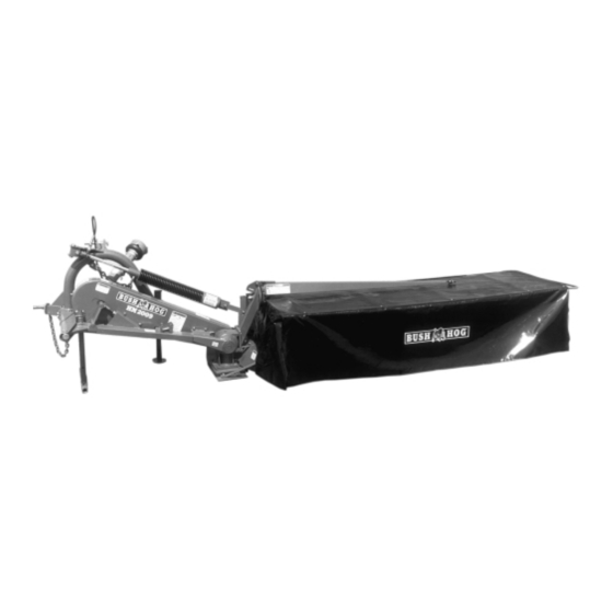
- Page 1 BUSH HOG ® GEARDRIVE HAY MOWERS Models HM2007, HM2008, & HM2009 Operator’s Manual ASSEMBLY OPERATION MAINTENANCE 1100 $4.00 Part No. 50030712...
- Page 2 If your manual should become lost or destroyed, Bush Hog will be glad to provide you with a new copy. Order from Bush Hog, P. O. Box 1039, Selma, Alabama 36702-1039.
-
Page 3: Table Of Contents
It is the Retail Customer’s responsibility to deliver the product to the authorized Bush Hog Dealer, from whom he purchased it, for service or replacement of defective parts which are covered by warranty. -
Page 4: Warranty
2. If the unit has been subjected to misapplication, abuse, misuse, negligence, fire or other accident. 3. If parts not made or supplied by Bush Hog have been used in connection with the unit, if, in the sole judge- ment of Bush Hog such use affects its performance, stability or reliability. -
Page 5: Dealer Preparation Check List
DEALER PREPARATION CHECK LIST BEFORE DELIVERING MACHINE — The following check list should be completed. Assembly completed. Gearbox filled with oil. All fittings lubricated. All shields in place and in good condition. All fasteners torqued to specifications given in Torque Chart. All decals in place and readable. -
Page 6: Safety Alert Symbols
Safety Alert Symbol Signal Words Safety Signs The signal words DANGER, WARNING, AND CAUTION are used on the equipment safety signs. These words are intended to alert the viewer to the existence and the degree of hazard seriousness. White letters on RED Black letters on ORANGE Black letters on YELLOW This Safety Alert Symbol means: “ATTENTION! BECOME ALERT! -
Page 7: Safety Precautions
IMPORTANT SAFETY PRECAUTIONS This symbol is used to call attention to safe- ty precautions that should be followed by the operator to avoid accidents. When you see this symbol, carefully read the message that follows and heed its advice. Failure to comply with safety precautions could result in serious bodily injury. -
Page 8: Federal Laws And Regulations
IMPORTANT FEDERAL LAWS AND REGULATIONS* CONCERNING EMPLOYERS, EMPLOYEES AND OPERATIONS. *(This section is intended to explain in broad terms the concept and effect of the following federal laws and regulations. It is not intended as a legal interpretation of the laws and should not be considered as such). U.S. -
Page 9: Machine Measurements
Models HM2007 - HM2008 - HM2009 Transport 1170 mm (46”) 1040 mm (41”) 1095 mm (43”) (All measurements are approximate and stated in mm and inches) Model HM2007 - 3680 mm (145”) Model HM2008 - 4060 mm (160”) Model HM2009 - 4440 mm (175”) Model HM2007 - 1900 mm (75”) -
Page 10: Technical Data
High cut skids (extra equipment ) . . mm (in.) Generally about supplementary equipment: Machines are from the factory available with several options. See your Bush Hog dealer for more information on these options. This supplementary equipment and other extra equipment are mentioned on page 35. -
Page 11: Machine Identification
Machine Identification The machine serial number and manufacturer information can be found on the metal plate, as shown. - Page 12 kg / lb...
-
Page 13: General Safety Instructions
Safety Any operator, repairer and owner must be familiar with the warning instructions for the machine in this manual, before operations commence. Always work carefully with agricultural machinery. Read through and observe the safety instructions in this manual. Safety is your responsibility. Pay particular attention to this symbol. - Page 15 Spare parts. For safety reasons use only original spare parts. If injury occurs when using non- original spare parts the Bush Hog warranty is invalidated. Maintenance. Take care that the machine is properly maintained and kept in good safe working...
- Page 16 Model Kg ( lb.) HM2007 415 (915) HM2008 440 (970) HM2009 465 (1025)
- Page 17 Safety instructions during crane lift Only use approved crane material. The machine must be in working position. Weight is stated on the drawing. Make sure that crane straps are securely fastened before lifting. Use a guide rope (not shown) to keep the machine in position.
- Page 19 Read the directions for use. Great care must be taken, when starting up a new machine. Incorrect mounting, wrong operations, etc., can result in expensive repairs and loss of profits. Bush Hog’s factory warranty is voided if the instructions of this manual are not adhered to.
- Page 20 HM2009 HM2009 HM2007, HM2008 HM2008 HM2007...
-
Page 21: Preparation For Use
The three point lift hitch may then be moved slightly forward and swung down and forward. After this the hitch can be turned to the left, so that the carrying tube can be lubricated at full length. Model Color HM2007 Green HM2008 Green HM2009 Black NOTICE... - Page 22 Clip Pin Pawl Remove Clip Pin and Rotate Pawl...
-
Page 23: Mounting
Mounting - coupling The coupling between machine and tractor must be carried out as explained in the instructions. If the machine becomes disconnected from the tractor it could cause severe damage or death. Fitting of the suspension Check that the lift arms of the tractor are adjusted to the same height from the ground. Turn the drawbar (A) to the side or remove it. - Page 24 Shortest Cutting Height min. 150 mm (6”)
-
Page 25: Pto Shaft
1000 rpm PTO output to a machine intended for 540 rpm PTO input speed. PTO ADAPTERS SHOULD NOT BE USED WITH ANY BUSH HOG EQUIPMENT. FAILURE TO FOLLOW THESE INSTRUCTIONS WILL CAUSE DRIVELINE FAILURE AND POSSIBLE TRACTOR DAMAGE. - Page 26 450 - 480 mm (Model HM2009 - max. 450 mm/18”) (18” - 19”) Model HM2007 - 13mm (1/2”) Model HM2008 - 11mm (7/16”) Model HM2009 - 8 mm (5/16”)
-
Page 27: Height Of The Suspension
Height of the suspension Important The working height of the suspension 450 - 480 mm (18 - 19”) is maintained with the chain (A). The chain is locked as shown at (B). NOTE: If the machine is equipped with high cut skids the working height of the linkage must be 500 - 530 mm (20 - 21”). - Page 28 Transport Position Un-Hitched Lock Pawl Engaged Support Legs Chain...
-
Page 29: Transport - Unhitching
Transport - Unhitching Transport As shown the machine can be raised to the vertical position. Raise the machine clear of the ground with the lift arms (A) of the tractor, then raise the machine to the vertical position with the hydraulic cylinder of the machine. - Page 30 95 ± 5 80 ± 5 60 ft./lbs. 70 ft./lbs.
-
Page 31: Maintenance
Maintenance During all service operations concerning knives and cutting discs the tractor engine must be stopped and the hand brake activated. If the machine is in the raised posi- tion it must be firmly supported. Also refer to page 5, item 10. Re-tighten the bolts of the cutting discs and knives on your new machine before starting and again after about 1 hour of operation. - Page 32 Hole In Front Belt Guard...
-
Page 33: Lubrication
(remove the complete lifting cylinder at the connection link on the gearbox), or coat the exposed surface of piston rod with grease. Models HM2007 - HM2008 - HM2009 (D) = 0 mm (Lubricants, - see page 46) - Page 34 Oil Filler Plug...
- Page 35 Amount of oil: Model HM2007 = 3.5 litres (3.7 qts.) and for following oil change approx. 3.1 litres (3.3 qts.). Model HM2008 = 4.0 litres (4.2 qts.) and for following oil change approx. 3.6 litres (3.8 qts.). Model HM2009 = 4.5 litres (4.8 qts.) and for following oil change approx. 4.1 litres (4.3 qts.).
- Page 36 Swath Roller Swath Board...
-
Page 37: Optional Equipment
Optional equipment Right-hand & Left-hand swath rollers The machine can be equipped with swath rollers as shown. Right-hand & Left-hand swath boards The machine can be equipped with swath boards as shown. - Page 38 1 Hillside Kit As Seen From Below 2-3 mm (5/16 - 1/8”) 4 Outside High Skid 3 Inside High Skid...
- Page 39 Optional hillside kit The spring lock keeps the machine in position in proportion to the tractor. If the machine meets a firm obstacle, the lock is released and the machine swings to the rear. Refer to the Hillside Kit Instructions for more information. The spring lock must be adjusted.
- Page 40 Throwing Wings Flat Blades Left Cone...
- Page 41 Throwing wings are recommended for very light grass conditions. Left cone The cone (B) at gearbox is standard equipment for model HM2008 and model HM2009. It is avail- able for model HM2007 as extra equipment. The cone is recommended for mowing of long, wilted...
- Page 42 1.4 - 2.8 mm (.055 - .110”) 0 - .05mm (0 - .002”)
-
Page 43: Direction For Repair
Directions for repair Repair must only be carried out by competent persons with experience of using work- shop equipment and trained in the repair of agricultural machinery in a safe and responsible manner. Stabilizer Be careful. Remove stabilizer from machine for disassembly. Never disassemble the stabilizer (A) without use of special tools (B). - Page 45 Cutterbar Be particularly attentive when checking or repairing the cutterbar - it rotates at 3000 rpm. Take care that worn bearings and gear wheels must be replaced in time. Otherwise a single damaged bearing might cause damage to the whole cutterbar. Use LOCTITE when stated - hardening time approx.
-
Page 46: Problem/Fault Analysis & Corrections
Disengage stabilizer lock. Adjust right hand lifting arm tractor correctly. Check correct fitting. Model HM2007 and model HM2008 thread - diameter = 13mm (.51”) . Color = green. Model HM2009 thread - diameter = 15 mm (.59”). Color = black. -
Page 47: Winter Storage
Winter storage When the season is finished, preparation for winter storage should take place immediately. Start by thoroughly cleaning the machine - then grease the machine thoroughly so that any remaining water is pressed out of the bearings. Change the oil in cutterbar and gearbox and let the machine rotate for a few minutes. -
Page 48: Conversion Chart & Lubricants
Conversion Chart BASIC UNIT: LENGTH ....AREA ..... . VOLUME . -
Page 49: Assembly Instructions
Models HM2007, HM2008 & HM2009 ASSEMBLY INSTRUCTIONS For transport from the factory to the user the machine has been disman- tled into main components. The following assembly instructions will tell you how to reassemble the machine. Please follow the assembly order shown and use the types and sizes of bolts shown for assembly of the parts. - Page 50 Figure 2 “U” Bracket Pivot Pin Mainframe Support Leg ASSEMBLY 1. Unbolt steel shipping frame. (Figure 1) These frame members will be discarded. Remove plastic wrapping and cut wiring that holds loose pieces together. 2. Arrange loose parts on floor for easy identifi- cation.
- Page 51 Figure 4 Front Support Leg Apply Grease At Contact Points 7. Fasten curtain frame upright bracket to gear- box using (3) 12 x 30mm bolts, and (1) 12 x 40mm bolt. The 12 x 40mm bolt is located in the bottom rear hole.
- Page 52 (Figure 8) Figure 8 Cylinder Mounting Hole Locations Model HM2009 Models HM2007 & HM2008 11. Remove pin from lower connection link and stop link to allow installation of lower end of stabilizer. 12. Pin stabilizer in appropriate top hole according to size of cutter bar.
- Page 53 “cut out” for clearance. A snap-in plas- tic cap is provided for each cone. Figure 10 Green - NOTE: Only used with flat blade kit Models HM2007, HM2008, HM2009 (Outside Crop Divider) Cutting Disc Offset Note the correct mounting of the cutting disc which is to be 3 mm offset.
- Page 54 CUTTING DISCS ARRANGEMENT Model HM2009 Model HM2008 Model HM2007 Blade Rotation Working Direction Working Direction Working Direction Gearbox Gearbox Gearbox...
- Page 55 15. Assemble curtain frame as shown in (Figure 11). Do not attach curtain frame to upright bracket at this time. Figure 11 Curtain Frame 10 - 35 mm 16. Place curtain over frame. Connect curtain frame to upright mount with rubber and metal discs “sandwiched”...
- Page 56 18. Attach front edge rail to frame. (Figure 14) 19. Install top support over curtain and frame. (Figure 16) Note that pawl must be inserted into place Figure 14 Figure 15 before inner end of support is bolted to the upright bracket.
- Page 57 20. Attach limit chain and circular shield as shown in (Figure 17). 21. Attach Slow Moving Vehicle (SMV) bracket to three point lift hitch as shown. (Figure 18) 22. While leaving slack in hydraulic hose, clamp it to the three point lift hitch. (Figure 8) 23.
- Page 58 OPTIONAL EQUIPMENT Right Hand Swath Wheel Left Hand Swath Wheel Right Hand Swathboard (Shipped preassembled) 12 - 35mm (Shipped from factory with bolts in mounting bracket)
-
Page 59: Safety Decals
To promote safe operation, Bush Hog supplies safety decals on all products manufactured. Because damage can occur to safety decals either through shipment, use or reconditioning, Bush Hog will, upon request, provide safety decals for any of our products in the field at no charge. Contact your authorized Bush Hog dealer for more information. - Page 62 BUSH HOG ® , L.L.C. P.O. Box 1039 Selma, AL 36702-1039 Telephone (334) 872-6261...
Need help?
Do you have a question about the HM2008 and is the answer not in the manual?
Questions and answers