Table of Contents
Advertisement
Quick Links
PUBLISHED September, 2017
Revised October, 2018
This Operator's Manual is an
integral part of the safe operation
of this machine and must be
maintained with the unit at all
times. READ, UNDERSTAND, and
FOLLOW
the
Operation Instructions contained
in this manual before operating
the equipment. C01-Cover_A
© 2015 Alamo Group Inc.
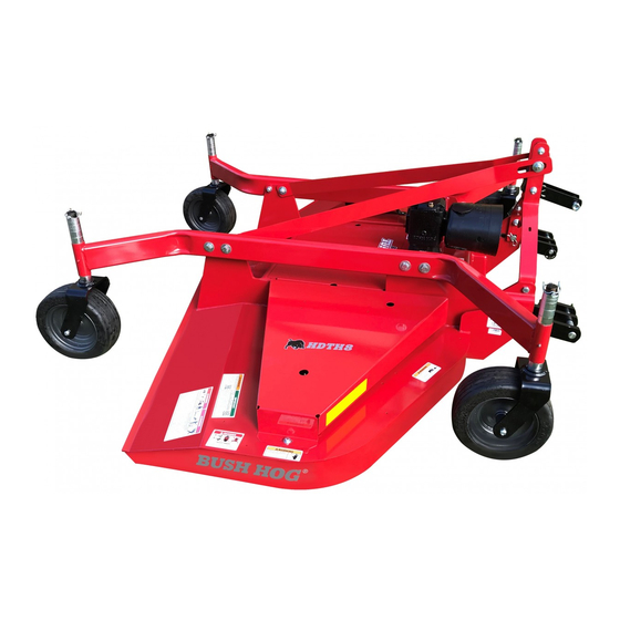
MODEL HDTH7
REAR DISCHARGE
Important
and Safety Instructions
are found in the Mower
Safety Video that can
Safety
and
be instantly accessed
on
www.algqr.com/bve
FINISH MOWER
PART NO. 50078487
Operating
the
internet
at:
Advertisement
Table of Contents

Related Manuals for Bush Hog HDTH7


Summary of Contents for Bush Hog HDTH7
- Page 1 MODEL HDTH7 REAR DISCHARGE FINISH MOWER PUBLISHED September, 2017 PART NO. 50078487 Revised October, 2018 This Operator's Manual is an integral part of the safe operation Important Operating of this machine and must be and Safety Instructions maintained with the unit at all are found in the Mower times.
- Page 5 SERIAL NUMBER LOCATION...
-
Page 7: Table Of Contents
TABLE OF CONTENTS SAFETY SECTION 1 General Safety Instructions and Practices ......................1-1 Operator Safety Instructions and Practices......................1-2 Connecting or Disconnecting Implement Safety Instructions and Practices ............1-3 Crushing Hazards..............................1-4 Thrown Objects Hazards ..........................1-5 &1-6 Run Over Hazards...............................1-7 PTO EntanglementHazards..........................1-8 Mower Blade Contact Hazards..........................1-9 Electrical & Fire Hazards...........................1-10 Transporting Hazards ............................1-11 Maintenance Hazards ............................1-12 Parts Information ...............................1-13... - Page 8 TABLE OF CONTENTS - CONTINUED OPERATION SECTION 4 (Continued) Driving the Tractor and Implement......................4-14 - 4-22 Disconnecting the Mower From the Tractor ......................4-22 Mower Storage ..............................4-23 Transporting the Tractor and Implement ......................4-23 Transporting on Public Roadways ......................4-24 - 4-25 Hauling Tractor and Implement .........................4-26 Trouble Shooting.............................4-27 - 4-28 MAINTENANCE SECTION 5 Lubrication (LUBRICATION POINTS LOCATIONS)....................5-1...
- Page 9 SAFETY SECTION...
- Page 11 SAFETY HDTH 7 Finish Mower 10/17 Safety Section 1-1 © 2017 Alamo Group...
- Page 12 SAFETY Safety Section 1-2 HDTH 7 Finish Mower 10/17 © 2017 Alamo Group...
- Page 13 SAFETY HDTH 7 Finish Mower 10/17 Safety Section 1-3 © 2017 Alamo Group...
- Page 14 SAFETY Safety Section 1-4 HDTH 7 Finish Mower 10/17 © 2017 Alamo Group...
- Page 15 SAFETY HDTH 7 Finish Mower 10/17 Safety Section 1-5 © 2017 Alamo Group...
- Page 16 SAFETY Safety Section 1-6 HDTH 7 Finish Mower 10/17 © 2017 Alamo Group...
- Page 17 SAFETY HDTH 7 Finish Mower 10/17 Safety Section 1-7 © 2017 Alamo Group...
- Page 18 SAFETY Safety Section 1-8 HDTH 7 Finish Mower 10/17 © 2017 Alamo Group...
- Page 19 SAFETY HDTH 7 Finish Mower 10/17 Safety Section 1-9 © 2017 Alamo Group...
- Page 20 SAFETY Safety Section 1-10 HDTH 7 Finish Mower 10/17 © 2017 Alamo Group...
- Page 21 SAFETY HDTH 7 Finish Mower 10/17 Safety Section 1-11 © 2017 Alamo Group...
- Page 22 SAFETY HAZARDS WITH MAINTENANCE OF IMPLEMENT Safety Section 1-12 HDTH 7 Finish Mower 10/17 © 2017 Alamo Group...
- Page 23 SAFETY HDTH 7 Finish Mower 10/17 Safety Section 1-13 © 2017 Alamo Group...
- Page 24 SAFETY Safety Section 1-14 HDTH 7 Finish Mower 10/17 © 2017 Alamo Group...
- Page 25 12 50074259 Made in America Decal 13 50078567 Bush Hog Logo Decal 14 50078485 Model Decal HDTH7 15 50078568 Bush Hog Logo Turf Decal 16 50035829 Owners Manual Tube 50078297 Owners Manual D708 Warning Decal, Avoid Equipment and Grass Fires...
- Page 26 SAFETY D418 D546 D559 D641 D646 Safety Section 1-16 HDTH 7 Finish Mower 10/17 © 2017 Alamo Group...
-
Page 27: Thrown Objects Hazards
SAFETY D708 DANGER DANGER Run Over Hazard - Injury or Death D851_2 D851 THROWN OBJECTS HAZARD TO AVOID SERIOUS INJURY OR DEATH: ALWAYS BUCKLE UP seat belt. Mower can throw objects up to 300 feet. TO AVOID SERIOUS ONLY START Tractor while seated in the operator's seat. D851 INJURY OR DEATH to operator or bystanders: STOP ENGINE and PTO, engage parking brake, lower implement,... - Page 28 SAFETY D855 D852 Safety Section 1-18 HDTH 7 Finish Mower 10/17 © 2017 Alamo Group...
-
Page 29: Federal Laws And Regulations
SAFETY Federal Laws and Regulations This section is intended to explain in broad terms the concept and effect of federal laws and regulations concerning employer and employee equipment operators. This section is not intended as a legal interpretation of the law and should not be considered as such. -
Page 31: Introduction Section
INTRODUCTION SECTION... - Page 33 INTRODUCTION We are pleased to have you as a Bush Hog customer. Your HDTH Series Rotary Cutter has been carefully designed to give maximum service with minimum down time.This manual is pro- vided to give you the necessary operating and maintenance instructions for keeping your rotary cutter in top operating condition.
- Page 34 B-section, Aramid Cord reinforced belt. Drivetrain protection is provided by belt slippage. EQUIPMENT SPECIFICATIONS HDTH7 Description Model HDTH7 Cutting Width..........60” Cutting Height (1/2" incr.) .......1 1/2" - 6 1/2" Tractor HP Range .........30-55 PTO Hitch Type ............Cat I & II Std. & QH Blade Size ............5/16"...
- Page 35 INTRODUCTION HDTH 7 Finish Mower 10/17 Introduction Section 2-3 © 2017 Alamo Group...
- Page 36 INTRODUCTION Introduction Section 2-4 HDTH 7 Finish Mower 10/17 © 2017 Alamo Group...
-
Page 37: Assembly Section
ASSEMBLY SECTION... -
Page 39: Dealer Setup Instructions
ASSEMBLY DEALER SETUP INSTRUCTIONS The mower as received from the factory is partially assembled and requires minimum time to complete assembly and is ready for sale. This mower is shipped vertically with shipping brackets. These shipping brackets are intended for use in trans- porting the mower from the factory to dealer. -
Page 40: Notice (Gearbox Oil)
ASSEMBLY NOTICE! The HDTH7 Gearboxes are shipped WITHOUT OIL in the Gearboxes and must be filled before connecting to the tractor and placing in operation! USE 85W / 90 GEAR OIL Oil Filler/Vent Plug Fill Check Plug OIL FILL PROCEDURE DO NOT OVER FILL GEARBOXES. 1. Remove the Oil Filler/Vent Plug on top the Gearbox. -
Page 41: Preparing To Assemble
ASSEMBLY The HDTH models are shipped from the factory partially assembled on shipping stands allowing the machine to be shipped in a vertical position. The shipping stands attached to the front of the machines must be removed prior to the assembly process. Do not attempt to remove the shipping stands with the machine in the vertical position. -
Page 42: Assembling The Hdth
ASSEMBLY Figure 3-2 See FLEX LINK HDTH Setup Instructions. Figure 3-3 or Figure 3-4 Assembly Diagram 1&1*1( See Detail “A” Detail “A” See LIFT PINS Cotter Pin ” x 1” ⁄ 3 2 Figure 3-5 ” 1* Flatwasher ⁄ 8 Mast t See CASTER WHEELS Driveline Holder 1&... -
Page 43: Flex Link Setup (Standard)
ASSEMBLY FLEX LINK SETUP Standard 3 Pt Lift (Figure 3-3) For standard 3 pt. lift attachment to tractor the Flex Link is attached to the mast in the upper holes just under the Mast Struts. Refer to Figure 3-3. 1. Place a Pivot Bushing through the rear holes of the Flex Link and install between the Mast uprights aligning the Bushing in the Flex Link with the holes in the Mast. - Page 44 ASSEMBLY FLEX LINK SETUP (continued) Quick Hitch 3 Pt Lift (Figure 3-4) For Quick Hitch pt. lift attachment to tractor the Flex Link is attached to the Mast in the lower holes of the Mast Struts. Refer to Figure 3-4. 1. Before assembling the Flex Link to the Mast the Extension Spring should be installed to the Pivot Bushing.
-
Page 45: Lift Pins
ASSEMBLY LIFT PINS Lift Pins 3 Pt Lift (Figure 3-5) 1. Install the Lift Arms into the pockets at the front of the machine. Install the category I & II lift pin in the front hole in the lift arms and secure with the Lynch Pin. 2. -
Page 46: Caster Wheels
ASSEMBLY CASTER WHEELS (Figure 3-6) The Caster Wheels are shipped in the inverted position from the factory and must be placed in the correct operating position for final assembly. 1. Raise and support the front of the mower enough so the Casters may be placed through the pivot tubes on the wheel mounts from the underside. -
Page 47: Driveline Attachment
ASSEMBLY DRIVELINE ATTACHMENT (Figure 3-7) The Driveline Supplied with the HDTH Series Finish Mowers are ASAE size 3 with 1-3/8”- 6 spline yokes.The im- plement yoke may have a locking push pin or a locking collar for the driveline to lock to the implement gearbox shaft. - Page 48 ASSEMBLY FRONT ROLLER KIT ASSEMBLY (OPTIONAL) (Figure 3-8) 1. Attach the Roller Mounting Brackets to the front of the deck using two 3/8” x 1” carriage bolts, , 3/8” lockwashers and 3/8” hex nuts in the front mounting holes and two 3/8” x 1-1/4” carriage bolts, 3/8” lockwashers and 3/8” hex nuts in the rear mounting holes as shown in figure (Figure 3-8) below.
-
Page 49: Operation Section
OPERATION SECTION... -
Page 51: Operation Instructions
UAL AND THE TRACTOR MANUAL BEFORE ATTEMPTING TO USE THE TRACTOR AND IMPLEMENT. If you do not understand any of the instructions, contact your nearest authorized Bush Hog Dealer for a full explanation. Pay close attention to all safety signs and safety messages contained in this manual and those affixed to the imple- ment and tractor. -
Page 52: Operator Requirements
OPERATION OPERATOR REQUIREMENTS Operation Section 4-2 HDTH 7 Finish Mower 10/17 © 2017 Alamo Group... -
Page 53: Tractor Requirements
OPERATION TRACTOR REQUIREMENTS Tractor Requirements and Capabilities • ASAE approved Roll-Over Protective Structure (ROPS) or ROPS cab and seat belt. • Tractor Safety Devices ......Slow Moving Vehicle (SMV) emblem, lighting, PTO master shield • Tractor Horsepower: -Minimum ........30HP -Maximum........55HP •... -
Page 54: Tractor Safety Devices
Tractor 3-Point Lift The tractor 3-point hitch must be rated to lift at least 954 lbs when attaching a HDTH7. The mower is designed to be mounted on tractors with a CAT I or Cat II Standard and Quick Attach Hitch. Refer to the tractor operator’s manual for the category of the tractor being used. -
Page 55: Power Take Off
OPERATION Power Take Off (PTO) NOTE: These mowers are designed for 540 RPM (PTO) speeds only. Depending on the unit, the mower is designed to operate at a PTO speed of 540 or 1000 RPM. Most tractors operate at either 540, or a combination of 540 and 1000 RPM PTO speeds. The operating speed of the mower and tractor can be determined by the number of splines on the driveline yoke and PTO output shaft. -
Page 56: Getting On And Off The Tractor
OPERATION GETTING ON AND OFF THE TRACTOR Before getting onto the tractor, the operator must read and completely understand the implement and tractor operator manuals. If any part of either manual is not completely understood, consult an authorized dealer for a complete explanation. OPS-U- 0007 Do not mount or dismount the Tractor while the tractor is moving. -
Page 57: Starting The Tractor
OPERATION STARTING THE TRACTOR The operator must have a complete understanding of the placement, function, and operational use of all tractor controls before starting the tractor. Review the tractor operator’s manual and consult an authorized dealer for tractor operation instructions if needed. Essential Tractor Controls: •... - Page 58 OPERATION Connecting the Mower (Figure 4-2) (Figure 4-2) Make sure the tractor is equipped with the correct PTO shaft. Change shafts if needed. Shorten or remove the tractor drawbar to avoid in- terference when raising and lowering the mower. Board the tractor and start the engine. Position the tractor to the mower with the 3-point lift arms posi- tioned at the same height and to the outside of the mower hitch pins.
-
Page 59: Driveline Length Modification
OPERATION Driveline Length Modification Before operating the Implement, check to make sure the Implement input driveline will not bottom out or become disengaged. Bottoming out occurs when the inner shaft penetrates the outer hous- ing until the assembly becomes solid-it can shorten no more. Bottoming out can cause serious damage to the Tractor PTO by pushing the PTO into the Tractor and through the support bearings or downward onto the PTO shaft, breaking it off. -
Page 60: Setting The Mower
OPERATION SETTING THE MOWER Properly setting the cutting height is essential for efficient and safe operation. A properly set mower will make a more uniform cut, distribute clippings more evenly, require minimal tractor work, and follow the contour of uneven terrain. NOTE: Avoid very low cutting heights, striking the ground with the blades gives the most damaging shock loads and will cause damage to the mower and drive. -
Page 61: Pre-Operation Inspection And Service
OPERATION PRE-OPERATION INSPECTION AND SERVICE Before each use, a pre-operation inspection and service of the implement and tractor must be performed. This includes routine maintenance and scheduled lubrication, inspecting that all safety devices are equipped and functional, and performing needed repairs. DO NOT operate the unit if the pre-operation inspection reveals any condition affecting safe operation. -
Page 62: Mower Pre-Operation Inspection/Service
OPERATION Mower Pre-Operation Inspection/Service Before each mower use, a complete inspection and service is required to ensure the mower is in a good and safe working condition. Damaged and/or broken parts should be repaired and/or replaced immediately. To ensure the mower is ready for operation, conduct the following. - Page 63 OPERATION Gearbox Vent • Inspect the gearbox oil level. A low oil level is a warning Plug sign that the gearbox may be cracked or its seal is Oil Level damaged and needs replacement. Check Plug • Ensure the gearbox vent is in place and free from clogs.
-
Page 64: Driving The Tractor And Implement
OPERATION DRIVING THE TRACTOR AND IMPLEMENT Safe tractor transport requires the operator possess a thorough knowledge of the model being operated and precau- tions to take while driving with an attached implement. Ensure the tractor has the capacity to handle the weight of the implement and the tractor operating controls are set for safe transport. - Page 65 OPERATION Starting the Tractor The procedure to start the tractor is model specific. Refer to the tractor operator’s manual for starting procedures for your particular tractor. Consult an authorized dealer if the starting procedure is unclear. Ensure the 3-point con- trol lever is in the lowered position and the PTO is disen- gaged before starting the tractor.
- Page 66 OPERATION Raising the Mower Using the tractor 3-point hitch control lever, raise the mower off the ground about 6”, or just high enough to clear any ground obstacles. When raising the mower, make sure all connection points are securely attached and at least 1”...
- Page 67 OPERATION Damage resulting from over-collapse of the driveline’s inner profile and its outer housing may allow the driveline to come loose from the Tractor which could cause bodily injury to the operator or bystanders and/or extensive damage to the Tractor or Implement. OPS-R-0020 When confronted with an incline or ditch, do not approach from an angle which is perpendicular or straight on as damaged to over collapse of the driveline may occur.
- Page 68 OPERATION OPERATING THE TRACTOR AND IMPLEMENT THE OPERATOR MUST COMPLETELY UNDERSTAND HOW TO OPERATE THE TRACTOR AND IMPLEMENT AND ALL CONTROLS BEFORE ATTEMPTING TO OPERATE. The operator must read and understand the Safety and Operation Sections of the implement and tractor operator’s manuals. These manuals must be read and explained to any operator who cannot read.
- Page 69 OPERATION Bystanders/Passersby Precautions Rotary Mowers are capable under adverse conditions of throwing objects for great distances (300 feet or more) and causing serious injury or death. Follow safety messages carefully. If a bystander comes within 300 feet of the tractor while the mower is being operated, stop the tractor at once, idle the engine and disengage the PTO.
- Page 70 OPERATION PTO RPM and Ground Speed Ground speed for mowing will depend upon the height, type, and density of vegetation to be cut. Recommended speed for efficient mower performance is between 2 and 5 mph(3-8 kph). Operate the mower at its full rated PTO speed to maintain blade speed for a clean cut.
- Page 71 OPERATION Follow these guidelines to reduce the risk of equipment and grass fires while operating, servicing, and repairing the Mower and Tractor: ● Equip the Tractor with a fire extinguisher in an accessible location. ● Do Not operate the Mower on a Tractor with an underframe exhaust. ●...
-
Page 72: Disconnecting The Mower From The Tractor
OPERATION Shutting Down the Mower To shut down the mower operation: 1. Bring the tractor to a complete stop on a level surface. 2. Decrease the engine speed (RPM) to idle. 3. Place the transmission in park or neutral and apply the parking brake. 4. -
Page 73: Mower Storage
OPERATION MOWER STORAGE Properly preparing and storing the mower at the end of the season is critical to maintaining its appearance and to help ensure years of dependable service. The following are suggested storage procedures: • Thoroughly clean all debris off the mower to prevent damage from rotting grass and standing water. •... -
Page 74: Transporting On Public Roadways
OPERATION If the tractor’s hydraulic pump is not independent of the tractor PTO, or if the tractor PTO has to be run to have hydraulic power, disconnect the mower driveline from the tractor PTO output shaft. Secure the driveline to the mower deck to prevent driveline damage or loss during transport OPS-R-0034... - Page 75 OPERATION Make certain that the “Slow Moving Vehicle” (SMV) sign is installed in such a way as to be clearly visible and legible. When transporting the Equipment use the Tractor flashing warning lights and follow all local traffic regulations. (SG-6) The SMV (Slow Moving Vehicle) emblem is the universal symbol used to alert drivers of the presence of equipment traveling on road- ways at a slow speed.
-
Page 76: Hauling Tractor And Implement
OPERATION Hauling the Tractor and Implement Before transporting a loaded tractor and implement, meas- ure the height and width dimensions and gross weight of the complete loaded unit. Ensure that the load will be in compli- ance with the legal limits set for the areas that will be trav- eled through. -
Page 77: Trouble Shooting
Belt Slipping Tighten or replace with special Bush Hog belt Grass wet Allow grass to dry before mowing. Slow ground speed of tractor but keep engine running at full PTO rpm. - Page 78 OPERATION TROUBLE SHOOTING GUIDE Problem Possible Cause Remedy FRAYED EDGES ON COVER Belt misaligned or belt rubbing Re-align belt or guide. Be sure belt guide. doesn’t rub any other part while running. Pulley misalignment. I inspect to ensure belt is running in center of backside idler.
-
Page 79: Maintenance Section
MAINTENANCE SECTION... -
Page 81: Lubrication (Lubrication Points Locations)
MAINTENANCE Before operating your Finishing Mower, make sure it is properly lubricated and thoroughly inspected. Only a minimum of time and effort is required to regularly lubricate and maintain this machine to provide long life and trouble free operation. Lubrication Do not let excess grease collect on or around parts, particularly when operating in sandy areas. -
Page 82: Gearbox Maintenance
MAINTENANCE Gearbox Maintenance The first oil change must be done after 50 hours of working time and then after 400-500 hours of work. Keep in mind that intense and continuous working conditions will necessitate more frequent oil changes and periodic checks. It is a good practice to check the oil level every 50-60 hours of work. -
Page 83: Driveline Maintenance
MAINTENANCE DRIVELINE MAINTENANCE The Driveline should be serviced every 8 hours of operation. Refer to (Figure 5-3) 1. Disconnect the driveline from the Tractor PTO and from the Gearbox input shaft. 2. Pull the driveline halves apart. 3. Release the Shield Cones from the shield tubes by pressing down on the retaining tabs located under the access holes on the back of the shield cones (there are 3 tabs on each cone) and separate the shield tubes from the cones exposing the driveshaft inner and outer tubes. -
Page 84: Blade Spindle And Belt Tension Idler Arm Lubrication And Maintenance
MAINTENANCE BLADE SPINDLE and BELT TENSION IDLER ARM LUBRICATION & MAINTENANCE The area beneath the shielding must be cleaned of debris such as grass clippings and twigs to prevent buildup, causing friction on belt and pulleys. Clean any lubricant accumulation occuring during the lubrication procedures. Check drive pulleys and idler pulleys for excessive wear or damage. -
Page 85: Blade Servicing
MAINTENANCE BLADE SERVICING Inspect blades before each use to determine that they are properly installed and in good condition. Replace any blade that is bent, excessively nicked, worn, or has any other damage. Small nicks can be removed by sharpen- ing. -
Page 86: Blade Removal
MAINTENANCE BLADE REMOVAL Never work under the implement, or any lifted component unless the imple- ment is securely supported or blocked to prevent sudden or inadvertant falling which can cause serious injury or death. 1. Raise cutter using tractor hydraulics and SECURELY BLOCK INTO POSITION. 2. -
Page 87: Belt Adjustment
Belt Removal and Replacement (Figure 5-7) Note: Use only Genuine Bush Hog Belts for replacement. Will Fit (after market belts) may not meet the re- quirements for usage in belt life and mower performance. -
Page 88: End Of Season Storage
MAINTENANCE END of SEASON STORAGE Your rotary cutter represents an investment from which you should get the greatest possible benefit. Therefore, when the season is over, the cutter should be thoroughly checked and prepared for storage so that a minimum amount of work will be required to put it back into operation for the next season. - Page 89 MAINTENANCE HDTH 7 Finish Mower 10/17 Maintenance Section 5-9 © 2017 Alamo Group...
Need help?
Do you have a question about the HDTH7 and is the answer not in the manual?
Questions and answers