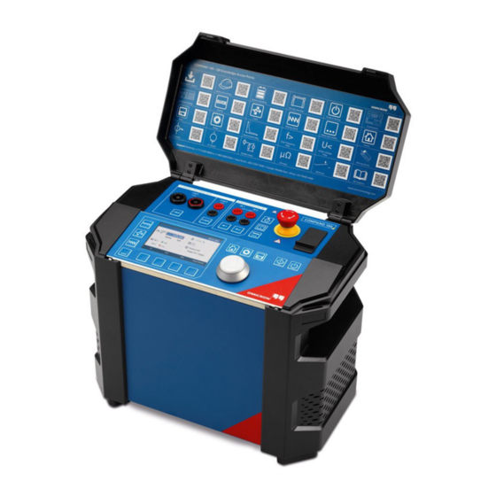
Omicron SAA1 Supplementary Sheet

Omicron SAA1 Supplementary Sheet

Beeper dongle, warning lamp, 3-position remote safety switch

Advertisement

Supplementary Sheet
Functions and Handling of Safety Accessories
Document ID
ENU 1191 14 04
Abstract
This document describes the functions and handling of the following accessories:
-
SAA1 Beeper Dongle
-
SAA2 Warning Lamp
-
SAA3 3-Position Remote Safety Switch
-
CP Strobe Warning Lamp
It includes the designated use, information about the compatibility with different main devices as well as
operation, connection, disconnection and cleaning instructions. Furthermore, the technical data for each
accessory can be found in the corresponding chapter.

Advertisement

Table of Contents
loading

Summary of Contents for Omicron SAA1

  • Page 1 Document ID ENU 1191 14 04 Abstract This document describes the functions and handling of the following accessories: SAA1 Beeper Dongle SAA2 Warning Lamp SAA3 3-Position Remote Safety Switch CP Strobe Warning Lamp It includes the designated use, information about the compatibility with different main devices as well as operation, connection, disconnection and cleaning instructions.
  • Page 2 We have done our best to ensure that the information given in this Supplementary Sheet is useful, accurate and entirely reliable. However, OMICRON does not assume responsibility for any inaccuracies which may be present.
  • Page 3: Table Of Contents

    Disclaimer ............................8 Related documents ........................8 Compliance statement ........................9 Recycling ............................9 Compatibility with OMICRON test systems ..................10 Connecting with main devices ......................14 Cascadability ..........................14 Use of the main device Safety Connector Dongle(s) ..............15 SAA1 Beeper Dongle ..........................
  • Page 4 Connection ........................... 44 Testing ............................45 Disconnection ..........................46 Cleaning ............................46 Technical data ..........................47 Support ............................48 24/7 Technical support - get support ................... 48 Customer area - stay informed ....................48 OMICRON Academy - learn more ....................48 OMICRON...
  • Page 5 Death or severe injury will occur if the appropriate safety instructions are not observed. WARNING Death or severe injury can occur if the appropriate safety instructions are not observed. CAUTION Minor or moderate injury may occur if the appropriate safety instructions are not observed. NOTICE Equipment damage or loss of data possible. OMICRON...
  • Page 6: Safety Instructions

    Operator qualifications Working on high-voltage assets can be extremely dangerous. Only authorized personnel who are qualified, skilled and regularly trained in electrical engineering are allowed to operate OMICRON test systems and their accessories. Before starting to work, clearly establish the responsibilities.
  • Page 7: Using This Supplementary Sheet

    Supplementary Sheet. If you do not understand some safety instructions, contact OMICRON before proceeding. Maintenance and repair of the Safety Accessories is only permitted by qualified experts at OMICRON Service Centers (see "Support" on page 48). When handling and operating any Safety Accessory, observe the safety instructions in the User Manual of...
  • Page 8: Disclaimer

    Safety Accessories as part of the related test systems. Table 1: Related documents Title Description Contains safety information and use case examples for the SAA1 User Manual SAA1 Beeper Dongle. Contains safety information and use case examples for the CIBANO 500 Getting Started CIBANO 500 test system.
  • Page 9: Compliance Statement

    For customers in EU countries (incl. European Economic Area) OMICRON test sets are subject to the EU Waste Electrical and Electronic Equipment Directive 2012/19/EU (WEEE directive). As part of our legal obligations under this legislation, OMICRON offers to take back the test set and ensure that it is disposed of by authorized recycling agents.
  • Page 10: Compatibility With Omicron Test Systems

    The aim of the Safety Accessories described in this document is to increase the safety during operation of OMICRON test systems. Use the Safety Accessories ONLY with compatible main devices of test systems and their accessories. Using other main devices of other test systems may impair the protection and functionalities provided by the Safety Accessory.
  • Page 11 Compatibility with OMICRON test systems Table 3: SAFETY output connector(s) on the main devices CIBANO 500 SAFETY OUTPUT NOTE! When connecting the Safety Accessory SAA2 Warning Lamp to the CIBANO 500 use ONLY SAFETY 1 connector for the connection. CPC 80/100...
  • Page 12 Safety Accessories Supplementary Sheet TESTRANO 600 SAFETY OUTPUT NOTE! When connecting the Safety Accessory SAA2 Warning lamp to the TESTRANO 600 use ONLY SAFETY 1 connector for the connection. COMPANO 100 SAFETY OUTPUT OMICRON...
  • Page 13 VOTANO 100 AND VBO2 SAFETY OUTPUT NOTE! Safety Accessories (SAA1 or SAA2) can be used with VOTANO 100 only by first connecting the VBO2 to the VOTANO 100 and by connecting the Safety Accessory to the SAFETY connector on the VBO2 and connecting the SAB1 as the last Safety Accessory.
  • Page 14: Connecting With Main Devices

    VBO2) by using a 9-pin D-SUB connector, which is either integrated into the Safety Accessory (SAA1) itself or by using a safety connector cable, which has 9-pin D-SUB connectors either at both ends of the cable (SAA2) or at only the other end of the cable (SAA3).
  • Page 15: Use Of The Main Device Safety Connector Dongle(S)

    Connecting with main devices Use of the main device Safety Connector Dongle(s) OMICRON main devices (excluding VOTANO 100) are delivered with pre-installed Safety Connector Dongles. Some main devices are delivered with one Safety Connector Dongle (CPC 80/100, COMPANO 100) while others are delivered with two Safety Connector Dongles (CIBANO 500, TESTRANO 600). A Safety Connector Dongle is shown in Figure 1 further below.
  • Page 16: Saa1 Beeper Dongle

    SAA1 Beeper Dongle Designated use The SAA1 Beeper Dongle generates an acoustic signal when the test system's outputs are activated. Since CIBANO 500*, VOTANO 100, and TESTRANO 600 have an internal beeper, the SAA1 Beeper Dongle is optimized for use with the CPC 80 and the CPC 100.
  • Page 17: Operation

    NOTE! If you remove the SAA1 from the main device, the test system will only work if you plug in the Safety Connector Dongle into the SAFETY connector(s) of the main device.
  • Page 18: Connection

    Figure 3: Fixing the SAA1 Beeper Dongle and the Safety Connector Dongle (example main device: CPC 80/100) 5. Fix the SAA1 Beeper Dongle and the Safety Connector Dongle by turning the locking wheel on both sides of the SAA1 Beeper Dongle and fastening the locking screws on the Safety Connector Dongle.
  • Page 19: Testing

    5. Press the test button SAA1 and verify that the beeper inside the SAA1 does not emit an audio signal while the test button is being pressed. 6. If the SAA1 beeper emitted an audio signal in step 3 and did not emit an audio signal in step 5 it is working normally.
  • Page 20: Disconnection

    Safety Accessories Supplementary Sheet Disconnection To disconnect the SAA1 from the main device: 1. Make sure that the main device to which the SAA1 is connected to is switched off. WARNING Death or severe injury caused by high voltage or current possible.
  • Page 21: Technical Data

    SAA1 Beeper Dongle Technical data Table 6: SAA1 specifications Characteristic Rating Operating voltage 15 V DC Interface 9-pin D-SUB connector with locking screws Table 7: Climate Characteristic Rating Temperature Operating –10 ºC…+55 ºC / +14 ºF…+131 ºF Storage –30 ºC…+70 ºC / –22 ºF…+158 ºF Max.
  • Page 22: Saa2 Warning Lamp

    Figure 5: SAA2 Warning Lamp with its main components Compatibility with main devices SAA2 Warning Lamp is intended to be used together with the following main devices: • CIBANO 500 • CPC 80 / CPC 100 • TESTRANO 600 • VOTANO 100 OMICRON...
  • Page 23: Operation

    The SAA2 system is active when the control unit is powered, the connection to the SAFETY output of the main device is established and the main device’s Safety Connector Dongle is plugged into the OMICRON...
  • Page 24 Signal lamp Channel 1 Signal lamp Channel 2 NOTE! Back view of the SAA2. Unused channel connector (CH 1 or CH 2) must be terminated by inserting a SAA2 dongle into the unused CH connector. Figure 7: Rear view of the SAA2 OMICRON...
  • Page 25 In/Out plug from control unit, a connector wire to another signal lamp or SAA2 dongle NOTE! If not connecting to further SAA2 signal lamps the unused In/Out connector must be terminated with a SAA2 dongle. Figure 9: SAA2 signal lamp OMICRON...
  • Page 26 SAA2 control unit or the safety interface cable is defective. No light Power supply defective or not connected. Figure 10: Connecting the SAA2 to the test system, the SAA2 control unit power supply, a maximum of 6 x SAA2 signal lamps and the SAA2 dongles. OMICRON...
  • Page 27: Connection

    Death or severe injury caused by high voltage or current possible.  Use SAA2 only with the original power supply delivered by OMICRON.  The OMICRON power supply DC side negative is connected to the ground (PE). 5. Remove the Safety Connector Dongle from the SAFETY connector on the main device and plug it in the SAFETY OUT connector of the SAA2 control unit.
  • Page 28 10. With the controls on the front panel of the control unit, you can set following options: beeper on/off, red light continuous or flashing and light intensity. See Figure 6. OMICRON...
  • Page 29: Testing

    4. Release the Emergency Stop button and start the main device. Then the signal lamps should change from green to red. WARNING Death or severe injury caused by high voltage or current possible.  Contact OMICRON technical support if you observe any other behavior than described in this section. OMICRON...
  • Page 30: Disconnection

    SAFETY output connector. Cleaning To clean the SAA2, use a cloth dampened with isopropanol alcohol. WARNING Death or severe injury caused by high voltage or current possible.  Before cleaning the SAA2, always disconnect it from the main device. OMICRON...
  • Page 31: Technical Data

    < 95% relative humidity, non-condensing Table 14: Mechanical data Characteristic Rating Dimensions (w × h × d) 180 mm × 111 mm × 44 mm 7.1 inch × 4.4 inch × 1.74 inch Weight 620 g / 1.6 lb (without cable) OMICRON...
  • Page 32 / 65 ft/s ), 20 cycles per axis) Humidity IEC/EN 60068-2-78 (5%…95% relative humidity, non-condensing), tested at 40 ºC /104 ºF for 48 hours Protection class IP20, according to IEC/EN 60529 Does not apply to the 9-pin D-SUB connector. OMICRON...
  • Page 33: Signal Lamps

    12 000 m /40 000 ft Table 18: Mechanical data Characteristic Rating Dimensions (w × h × d) 200 mm × 80 mm × 70 mm 7.9 inch × 3.1 inch × 2.8 inch Weight 400 g / 0.9 lb (without cable) OMICRON...
  • Page 34 / 65 ft/s ), 20 cycles per axis) Humidity IEC/EN 60068-2-78 (5%…95% relative humidity, non-condensing), tested at 40 ºC / 104 ºF for 48 hours Protection class IP52, according to IEC/EN 60529 1. Does not apply to the 9-pin D-SUB connector. OMICRON...
  • Page 35: Saa3 3-Position Remote Safety Switch

    SAA3 3-Position Remote Safety Switch Designated use The SAA3 3-Position Remote Safety Switch is an emergency switch for use with OMICRON test systems listed in Table 2 on page 10. The SAA3 triggers the emergency stop of the connected test system.
  • Page 36: Operation

    NOTE! CIBANO 500 and COMPANO 100 do not have a separate physical key nor a software lock function. 3. Remove the Safety Connector Dongle from one of the SAFETY output connectors on the main device side panel and store it for later use. OMICRON...
  • Page 37: Testing

    2. Test the functionality of the SAA3 3-Position Remote Safety Switch as follows: a. Start by not pressing the SAA3 switch (Figure 15 part I). The main device/test system signal lamps should glow continuously green indicating that all outputs are switched off. OMICRON...
  • Page 38: Disconnection

    5. Connect the Safety Connector Dongle in to the SAFETY output connector of the main device. 6. The SAA3 has now been removed and the main device has the required Safety Accessory Dongle installed on the SAFETY output connector. OMICRON...
  • Page 39: Cleaning

    SAA3 3-Position Remote Safety Switch Cleaning To clean the SAA3, use a cloth dampened with isopropanol alcohol. WARNING Death or severe injury caused by high voltage or current possible.  Before cleaning the SAA3, always disconnect it from the main device. OMICRON...
  • Page 40: Technical Data

    12 000 m / 40 000 ft Table 25: Mechanical data Characteristic Rating Dimensions (w × h × d) 174 mm × 61 mm× 44 mm 6.9 inch × 2.4 inch × 1.7 inch Weight 1.38 kg / 3.0 lb (with cable) OMICRON...
  • Page 41 / 65 ft/s ), 20 cycles per axis) Humidity IEC/EN 60068-2-78 (5%…95% relative humidity, non-condensing), tested at 40 ºC / 104 ºF for 48 hours Protection class IP66, according to IEC/EN 60529 1. Does not apply to the 9-pin D-SUB connector. OMICRON...
  • Page 42: Cp Strobe Warning Lamp

    Designated use The CP Strobe Warning Lamp flashes whenever the connected test system may carry dangerous voltages and currents. The brightness is reduced when used in combination with the SAA1 Beeper Dongle on the CPC 80/100. Compatibility with main devices The CP Strobe Warning Lamp is intended to be used together with the following main devices: •...
  • Page 43: Operation

    Dangerous operating dangerous voltages and currents. condition DO NOT enter the high-voltage test area. Outputs of the test system are disabled. Safe operating condition KEEP FOLLOWING the five safety rules because voltage might be still present on the test object. OMICRON...
  • Page 44: Connection

    8. Unlock the Emergency Stop button on the main device or test system and unlock the main device with the key or via screen. NOTE! CIBANO 500 does not have a separate physical key nor a software lock function. 9. If all signal lamps light continuously green, the main device/test system is ready for operation. OMICRON...
  • Page 45: Testing

    Measurement Start/Stop button on the front panel of the main device. 5. Now, the CP Strobe Warning Lamp should flash while the test is running. 6. Press the main device’s Measurement Start/Stop button. 7. Press the main device’s Emergency Stop button. OMICRON...
  • Page 46: Disconnection

    Safety Accessories Supplementary Sheet WARNING Death or severe injury caused by high voltage or current possible.  Contact OMICRON technical support if the CP Strobe Warning Lamp is not flashing during the test. Disconnection To disconnect the CP Strobe Warning Lamp from the main device: 1.
  • Page 47: Technical Data

    86 mm × 86 mm× 83 mm 3.4 inch × 3.4 inch × 3.3 inch Weight 179 g / 0.39 lb (without cable) Table 32: Standards conformity EMC, safety Rating IEC/EN 61326-1 (industrial electromagnetic environment) FCC subpart B of part 15, class A OMICRON...
  • Page 48: Support

    Browse through the knowledge library and find application notes, conference papers, articles about daily working experiences, user manuals and much more. OMICRON Academy – learn more www.omicronenergy.com/academy Learn more about your product in one of the training courses offered by the OMICRON Academy. ENU 1191 14 04 OMICRON...

This manual is also suitable for:

Saa2Saa3Cp strobe

Table of Contents