Table of Contents
Advertisement
Quick Links
instructions for
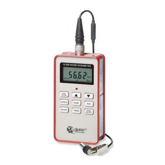
Q300
Noise Dosimeter
Note: Due to the new ATEX Directive in Europe, all references in this document to "Ex" or
"EEx" for intrinsic safety approvals should be disregarded effective 7/1/03 within the
member countries of the European Union (EU). At this time, this product is not approved
in accordance with the new ATEX Directive and is not sold for use in hazardous
atmospheres or explosive zones by customers within the EU. Outside of the EU, all
references to intrinsic safety continue without change.
1. INTRODUCTION TO THE Q-300 . . . . . . . . . . . . . . . . . . . . . . . . . . . . . . . . . . . . . . . . . . . . . . . . . . . . . . . . . . . . . . . . . . . . . 2
1.1 Assembling the Meter . . . . . . . . . . . . . . . . . . . . . . . . . . . . . . . . . . . . . . . . . . . . . . . . . . . . . . . . . . . . . . . . . . . . . . . 2
1.2 Initial Turn On and Check . . . . . . . . . . . . . . . . . . . . . . . . . . . . . . . . . . . . . . . . . . . . . . . . . . . . . . . . . . . . . . . . . . . . 3
1.3 Calibration . . . . . . . . . . . . . . . . . . . . . . . . . . . . . . . . . . . . . . . . . . . . . . . . . . . . . . . . . . . . . . . . . . . . . . . . . . . . . . . . 4
Storing the Calibration Value . . . . . . . . . . . . . . . . . . . . . . . . . . . . . . . . . . . . . . . . . . . . . . . . . . . . . . . . . . . . . . 5
1.4 Battery Installation and Removal . . . . . . . . . . . . . . . . . . . . . . . . . . . . . . . . . . . . . . . . . . . . . . . . . . . . . . . . . . . . . . . 6
2. ABOUT THE METER . . . . . . . . . . . . . . . . . . . . . . . . . . . . . . . . . . . . . . . . . . . . . . . . . . . . . . . . . . . . . . . . . . . . . . . . . . . . . . 7
2.1 The Display . . . . . . . . . . . . . . . . . . . . . . . . . . . . . . . . . . . . . . . . . . . . . . . . . . . . . . . . . . . . . . . . . . . . . . . . . . . . . . . 7
2.2 Keypad Functions . . . . . . . . . . . . . . . . . . . . . . . . . . . . . . . . . . . . . . . . . . . . . . . . . . . . . . . . . . . . . . . . . . . . . . . . . . 8
2.3 Acoustic Event Options . . . . . . . . . . . . . . . . . . . . . . . . . . . . . . . . . . . . . . . . . . . . . . . . . . . . . . . . . . . . . . . . . . . . . 11
2.4 Memory Capacity . . . . . . . . . . . . . . . . . . . . . . . . . . . . . . . . . . . . . . . . . . . . . . . . . . . . . . . . . . . . . . . . . . . . . . . . . 12
2.5 RESET - Erasing Stored Data . . . . . . . . . . . . . . . . . . . . . . . . . . . . . . . . . . . . . . . . . . . . . . . . . . . . . . . . . . . . . . . 12
2.6 Overload Detection . . . . . . . . . . . . . . . . . . . . . . . . . . . . . . . . . . . . . . . . . . . . . . . . . . . . . . . . . . . . . . . . . . . . . . . . 12
2.7 Security . . . . . . . . . . . . . . . . . . . . . . . . . . . . . . . . . . . . . . . . . . . . . . . . . . . . . . . . . . . . . . . . . . . . . . . . . . . . . . . . . 13
3. SETUP MENU . . . . . . . . . . . . . . . . . . . . . . . . . . . . . . . . . . . . . . . . . . . . . . . . . . . . . . . . . . . . . . . . . . . . . . . . . . . . . . . . . . . 16
CAL . . . . . . . . . . . . . . . . . . . . . . . . . . . . . . . . . . . . . . . . . . . . . . . . . . . . . . . . . . . . . . . . . . . . . . . . . . . . . . . . . 16
EVENT . . . . . . . . . . . . . . . . . . . . . . . . . . . . . . . . . . . . . . . . . . . . . . . . . . . . . . . . . . . . . . . . . . . . . . . . . . . . . . 16
RANGE . . . . . . . . . . . . . . . . . . . . . . . . . . . . . . . . . . . . . . . . . . . . . . . . . . . . . . . . . . . . . . . . . . . . . . . . . . . . . 17
UL . . . . . . . . . . . . . . . . . . . . . . . . . . . . . . . . . . . . . . . . . . . . . . . . . . . . . . . . . . . . . . . . . . . . . . . . . . . . . . . . . . 17
CL . . . . . . . . . . . . . . . . . . . . . . . . . . . . . . . . . . . . . . . . . . . . . . . . . . . . . . . . . . . . . . . . . . . . . . . . . . . . . . . . . . 17
ER . . . . . . . . . . . . . . . . . . . . . . . . . . . . . . . . . . . . . . . . . . . . . . . . . . . . . . . . . . . . . . . . . . . . . . . . . . . . . . . . . 17
TL . . . . . . . . . . . . . . . . . . . . . . . . . . . . . . . . . . . . . . . . . . . . . . . . . . . . . . . . . . . . . . . . . . . . . . . . . . . . . . . . . . 17
FAST/SLOW . . . . . . . . . . . . . . . . . . . . . . . . . . . . . . . . . . . . . . . . . . . . . . . . . . . . . . . . . . . . . . . . . . . . . . . . . . 17
A/C . . . . . . . . . . . . . . . . . . . . . . . . . . . . . . . . . . . . . . . . . . . . . . . . . . . . . . . . . . . . . . . . . . . . . . . . . . . . . . . . . 17
AO . . . . . . . . . . . . . . . . . . . . . . . . . . . . . . . . . . . . . . . . . . . . . . . . . . . . . . . . . . . . . . . . . . . . . . . . . . . . . . . . . 18
RT . . . . . . . . . . . . . . . . . . . . . . . . . . . . . . . . . . . . . . . . . . . . . . . . . . . . . . . . . . . . . . . . . . . . . . . . . . . . . . . . . . 18
BAUD . . . . . . . . . . . . . . . . . . . . . . . . . . . . . . . . . . . . . . . . . . . . . . . . . . . . . . . . . . . . . . . . . . . . . . . . . . . . . . . 19
EOL . . . . . . . . . . . . . . . . . . . . . . . . . . . . . . . . . . . . . . . . . . . . . . . . . . . . . . . . . . . . . . . . . . . . . . . . . . . . . . . . 19
FLOW . . . . . . . . . . . . . . . . . . . . . . . . . . . . . . . . . . . . . . . . . . . . . . . . . . . . . . . . . . . . . . . . . . . . . . . . . . . . . . . 19
TIME . . . . . . . . . . . . . . . . . . . . . . . . . . . . . . . . . . . . . . . . . . . . . . . . . . . . . . . . . . . . . . . . . . . . . . . . . . . . . . . . 20
PDOSE . . . . . . . . . . . . . . . . . . . . . . . . . . . . . . . . . . . . . . . . . . . . . . . . . . . . . . . . . . . . . . . . . . . . . . . . . . . . . . 20
LH-0 . . . . . . . . . . . . . . . . . . . . . . . . . . . . . . . . . . . . . . . . . . . . . . . . . . . . . . . . . . . . . . . . . . . . . . . . . . . . . . . . 20
SE20 . . . . . . . . . . . . . . . . . . . . . . . . . . . . . . . . . . . . . . . . . . . . . . . . . . . . . . . . . . . . . . . . . . . . . . . . . . . . . . . . 21
SE10 . . . . . . . . . . . . . . . . . . . . . . . . . . . . . . . . . . . . . . . . . . . . . . . . . . . . . . . . . . . . . . . . . . . . . . . . . . . . . . . . 21
InXX . . . . . . . . . . . . . . . . . . . . . . . . . . . . . . . . . . . . . . . . . . . . . . . . . . . . . . . . . . . . . . . . . . . . . . . . . . . . . . . . 21
PrnX . . . . . . . . . . . . . . . . . . . . . . . . . . . . . . . . . . . . . . . . . . . . . . . . . . . . . . . . . . . . . . . . . . . . . . . . . . . . . . . . 22
4. COMMUNICATIONS . . . . . . . . . . . . . . . . . . . . . . . . . . . . . . . . . . . . . . . . . . . . . . . . . . . . . . . . . . . . . . . . . . . . . . . . . . . . . . 23
4.1 Printing Data . . . . . . . . . . . . . . . . . . . . . . . . . . . . . . . . . . . . . . . . . . . . . . . . . . . . . . . . . . . . . . . . . . . . . . . . . . . . . 23
4.2 Parallel Printer Interface . . . . . . . . . . . . . . . . . . . . . . . . . . . . . . . . . . . . . . . . . . . . . . . . . . . . . . . . . . . . . . . . . . . . 25
4.3 RS-232 Serial Interface . . . . . . . . . . . . . . . . . . . . . . . . . . . . . . . . . . . . . . . . . . . . . . . . . . . . . . . . . . . . . . . . . . . . 30
4.4 Downloading Data . . . . . . . . . . . . . . . . . . . . . . . . . . . . . . . . . . . . . . . . . . . . . . . . . . . . . . . . . . . . . . . . . . . . . . . . 31
4.5 ASCII Commands . . . . . . . . . . . . . . . . . . . . . . . . . . . . . . . . . . . . . . . . . . . . . . . . . . . . . . . . . . . . . . . . . . . . . . . . . 33
5. GENERAL SOUND MEASUREMENT PRACTICES . . . . . . . . . . . . . . . . . . . . . . . . . . . . . . . . . . . . . . . . . . . . . . . . . . . . . . 35
5.1 Microphone Positioning . . . . . . . . . . . . . . . . . . . . . . . . . . . . . . . . . . . . . . . . . . . . . . . . . . . . . . . . . . . . . . . . . . . . . 35
5.2 Accuracy of Readings . . . . . . . . . . . . . . . . . . . . . . . . . . . . . . . . . . . . . . . . . . . . . . . . . . . . . . . . . . . . . . . . . . . . . . 36
5.3 Microphone Windscreen . . . . . . . . . . . . . . . . . . . . . . . . . . . . . . . . . . . . . . . . . . . . . . . . . . . . . . . . . . . . . . . . . . . . 36
5.4 Background Noise . . . . . . . . . . . . . . . . . . . . . . . . . . . . . . . . . . . . . . . . . . . . . . . . . . . . . . . . . . . . . . . . . . . . . . . . 37
56-447
Rev. F
6. TECHNICAL INFORMATION . . . . . . . . . . . . . . . . . . . . . . . . . . . . . . . . . . . . . . . . . . . . . . . . . . . . . . . . . . . . . . . . . . . . . . . 38
8/97
TABLE OF CONTENTS
Q-300 NOISE DOSIMETER
Advertisement
Table of Contents

Related Manuals for Quest Engineering Q300


Summary of Contents for Quest Engineering Q300
-
Page 1: Table Of Contents
Storing the Calibration Value ............. . 5 Q300 1.4 Battery Installation and Removal . -
Page 2: Introduction To The Q-300
6.1 Principles of Operation ..............38 6.2 Microphone Characteristics . -
Page 3: Assembling The Meter
The Q-300 performs the calculations for three dosimeters operating simultaneously in one instrument. A numerical readout of measurements for any of the three dosimeters may be displayed. The results of individual sound studies may be stored in internal memory for future reference. Meter operation is controlled from the keypad. Data may be sent to a parallel or serial printer, or to a computer by using an appropriate interface cable. -
Page 4: Calibration
The unweighted logging peak detector is also calibrated, setting its output at 3dB above the RMS level shown in the display. The Q300 must be calibrated at a frequency of 1kHz, as this condition is only true at 1kHz (and 6.2kHz). -
Page 5: Battery Installation And Removal
1.4 Battery Installation and Removal 2. ABOUT THE METER 2.1 The Display The battery must be a 9 Volt alkaline type. (Examples are: NEDA 1604A, IEC 6LF22, or IEC 6LR61) The LCD display provides the user with the selected measurement and the measurement parameters (A or C weighting, Replace the battery as follows (see Figure 4): FAST or SLOW response). -
Page 6: Keypad Functions
2.2 Keypad Functions ª « The LEVELS function key selects the group of items SPL, MAX, MIN or PEAK for display. The keys are used to select the specific item. Pressing LEVELS again selects the next dosimeter's (I, II or III) levels for display. If two or more dosimeters have identical measurement parameters, the higher number dosimeter will not be displayed. -
Page 7: Acoustic Event Options
Pause Time. The Current Event is indicated in the Setup Menu display as " Cxxx " where xxx is the event number. TWA - Time Weighted Average. The average level accumulated during a study, but calculated with an eight hour This is the event initiated the last time the Q300 was placed in RUN. integration time. -
Page 8: Memory Capacity
Setup Menu as SE1x and SE2x. at a set rate of once every minute. Run time without logging data is limited to 145 hours and 38 minutes. The Q300 will automatically PAUSE and display " AOL " if this limit is reached. Without logging, a maximum of 300 events is possible. - Page 9 If SE1 is enabled, after the unit is put into the RUN mode only the arrow and ENTER keys will operate. The display will read "0---". Press the arrow keys to set the first digit between 0 and 9. Pressing ENTER moves on to the next digit. After all four digits have been entered, the unit is no longer secured.
-
Page 10: Setup Menu
The event display will light the EVENT indicator and CXXX will show the current event (the event initiated the last time the Q300 was placed in RUN), with XXX being the event number. To view the current event, press the following key sequence: Threshold Level;... -
Page 11: Baud
Auto Run Options Communications Parameters Auto-On Time and Date. Set time and date that the Q-300 will turn on and go into Rmode (after a 10 BAUD Baud rate, or data rate for RS-232 communications. Set second warmup). The AO indicator will be to the same rate as the computer or printer being used. -
Page 12: Time
TIME Time of day, date, month and year are set one item at a time. Setting and storing one value Security Features advances to the next until all items have SE20 Security mode for locking all setup parameters. been stored. The displays are shown as follows: XX:XX Time (24 hour military time) -
Page 13: Prnx
4. COMMUNICATIONS PrnX Printout mode display, also used to determine the printout contents. Choices include turning logged data and statistics on or off and DEFINITIONS whether or not to print event summaries. The choices are displayed as follows: PARALLEL MODE: Data is passed along multiple wires simultaneously. This is used for sending information to parallel Logged Data Statistics Events... -
Page 14: Parallel Printer Interface
4.2 Parallel Printer Interface General Printer Configuration (Parallel and Serial) The Parallel Printer Interface is compatible with most Centronics compatible printers. The 056-957 contains electronics which Each line of print must end with the following two EOL (End of Line) characters: converts data from the Q-300 into parallel information. - Page 15 (HEADER and OVERALL SUMMARY) EVENT (1) Notes ____________________________________________________________________ __________________________________________________________________________ QUEST TECHNOLOGIES Session Started Session Stopped Run Time Q300 NOISE LOGGING DOSIMETER 18-MAR-95 @ 13:32:45 18-MAR-95 @ 14:53:21 1:21:36 Unit Version Number: 1.00 Serial Number: QC50100005 DOSIMETER 1 Peak Level 124.5dB...
-
Page 16: Rs-232 Serial Interface
4.3 RS-232 Serial Interface SLOW MAX (5 MINUTE TIME HISTORY) 13:37 113dB +====+====+==== 114dB The jack on the top of the Q-300 provides direct connection to a computer's COM port with the serial communications 14:02 109dB +====+==== 109dB cable (#056-707) provided. To connect to a serial printer or similar device, a 25-pin male to male gender changer is required. 14:27 117dB +====+====+====... -
Page 17: Downloading Data
Downloading Using Windows TERMINAL Baud rate and flow control must be set the same for both the Q-300 and the RS-232 device connected to it (BAUD and FLOW as set in the Setup Menu). Refer to section 3 COMM Setup Menu. Microsoft ®... -
Page 18: Ascii Commands
4.5 ASCII Commands - The following is a list of commands used to setup the Q-300 via RS-232. The display will automatically PRTx enables or disables the programmed run duration. x = Y for enabled, x = N for disabled. switch to the "... -
Page 19: General Sound Measurement Practices
5. GENERAL SOUND MEASUREMENT PRACTICES 5.2 Accuracy of Readings Before taking measurements with the Q-300 there is a series of quick checks that should be performed. After switching the unit ON, check for the LOBAT indicator in the display. Replace the battery if needed. For maximum accuracy, it is important to use the dosimeter correctly and to understand its limitations. -
Page 20: Technical Information
The effect of the "Noise Floor" on low level readings can cause inaccurate data. In a "Perfectly Quiet" room, the electrical noise produced by the microphone is approximately 35 dB on A weighting or 45 dB on C weighting. 6.2 Microphone Characteristics Measurements must always be at least 5 dB above the "Noise Floor". -
Page 21: Weighting Characteristics
6.3 Weighting Characteristics 6.4 Tone Burst Response The Q-300 has "A" and "C" weighting characteristics as shown in Figure 13. For most industrial and community noise Figures 14 and 15 show the meter's tone burst response to sinewave inputs of varied burst duration. The available time measurement requirements, the "A"... -
Page 22: Specifications
7. SPECIFICATIONS 8. ACCESSORIES Standards: ANSI S1.25 - 1991, ANSI S1.4 - 1983: Type 2 56-963 8mm Shoulder-Mount Dosimeter Microphone, Type 2. One piece system including Cable, Connector, and IEC 651 - 1979, IEC 804 - 1985: Type 2 Microphone IEC 1252 - 1993 58-852 Earloops to hold microphone at the ear, package of 10. -
Page 23: Using The Microphone Boom
Calibrators 8.2 AC/DC Adapter Installation Quest part number 056-973 056-981 QC-10 Calibrator; 114dB at 1000 Hz Output 056-982 QC-20 Calibrator; Selectable 94dB or 114dB at 250 Hz or 1000 Hz Output The dosimeter can operate from one of the following power sources if desired: 56-989 Calibrator Adapter, 8 mm to 1 inch coupler. -
Page 24: Troubleshooting
9.0 TROUBLESHOOTING APPENDIX Definitions Blank display when the ON/OFF key is pressed: All definitions are in reference to the Q-300 dosimeter. Replace the battery with a known fresh battery. BAUD: Baud Rate The rate of data transfer, in bits per second, between the dosimeter and a printer or computer in the serial output mode. Unit does not calibrate: Check for LOBAT indicator. -
Page 25: Typical Setups
85 dB for 8 Hours = 1 Pa maximum value (Slow or Fast Response) for the previous 1 second period. FAST: Fast Response STATISTICS: % Time Statistical Distribution A Measurement Time Constant, or averaging time, of 125 milliseconds. When Fast is used, SPL will closely track a For a given run time, the percentage of time that a sound level occured at a specific dB level. -
Page 26: Acoustical Formulas
Acoustical Formulas The Q-300 uses the following formulas to calculate the accumulated data: Where: Sound Level in dB with the selected Time Constant (Slow or Fast). Its value is entered only if the Sound Level is greater than the Threshold Level. Otherwise, it is entered as minus infinity. 8 Hour Criterion Time. -
Page 27: Quest Service And Warranty Policy
QUEST SERVICE AND WARRANTY POLICY Service Policy The Quest product you have purchased is one of the finest acoustic instruments available. It is backed by our full one year warranty which seeks complete customer satisfaction. This is your assurance that you can expect prompt courteous service for your equipment from the entire Quest service organization.
Need help?
Do you have a question about the Q300 and is the answer not in the manual?
Questions and answers