
Related Manuals for Benetech GM3125


Summary of Contents for Benetech GM3125
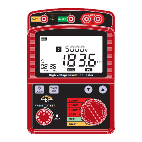
- Page 1 High voltage insulation tester User's Manual LINE CAT.Ⅲ 600V EARTH GUARD High Voltage Insulation Tester TIMER CLEAR 5000V 2500V PRESS TO TEST 1000V 500V LOCK AC.V Version: 3125-EN-0...
-
Page 2: Table Of Contents
CONTENTS 1. Before use notice Check-up--------------------------------- -------- ---(01) Safety warning-------------------------------------(02) Feature and function ----------------------------(04) Specifications ------------------------------------(05) Diagram of the unit -------------------------------(07) LCD display --------------------------------------- (09) 2.Operation Instructions Preparation before measurement-------------(11) Voltage measurement----------------------------(12) Insulation resistance measurement----------(14) Continuous measurement-----------------------(17) Timer measurement-------------------------------(18) Polarization index measurement--------------(20) The use of green protect-wire------------------(23) 3. -
Page 3: Before Use Notice
1. Before use notice Safety warning Designed to following safety standards: Check-up IEC 61010-1 CAT. Ⅲ 600V pollution level: 2 CAT. Ⅰ 5000V pollution level: 2 Carefully unpack your kit and ensure that you have IEC 61010-031 (test wire) the following items. In case that any items is missing or IEC 61326-1 (EMC) if you find any mismatch or damage, promptly contact IEC 60529 (Ip40) -
Page 4: Feature And Function
Features and functions Danger Do not measure if the voltage is above 600V. Auto- discharge function to make, the operation safe. Do not test at flammable / explosive hazard. LCD Back-light. Do not measure if the unit or your hand is wet. Do not go beyond the range of the tester Digital readout display. -
Page 5: Specifications
3.Technology parameter: Specifications: Technology parameter Technology index 1. Insulation resistance tester: Max. 999 counts LCD display Display (1000 counts only at 1T is displayed) Rated 500V 1000V 2500V 5000V voltage OL mark appears on insulation 0.0~99.9MΩ 0.0~99.9 MΩ 0.0~99.9 MΩ 0.0~99.9 MΩ... -
Page 6: Diagram Of The Unit
1.LCD display. Diagram of the unit TIMER :Time set button. :.Backlight button CLEAR LINE CAT.Ⅲ 600V EARTH GUARD 4.Test button. 5.Function switch. :Time choose button. 7.Red high voltage test wire socket. High Voltage Insulation Tester TIMER 8.Green protect test wire socket. CLEAR 5000V PRESS TO TEST... -
Page 7: 2.Operation Instructions
2.Operation instructions LCD Display Preparation before measurement 16 15 14 1. Check the battery voltage & battery replacement: a.Set the function switch to any position other than OFF. b. When the battery mark shown at the upper left on the LCD is “... -
Page 8: Voltage Measurement
2. Connecting test wires: Voltage measurement(30~600V) Insert the test wire firmly to the connector terminal on the instrument; Danger Connect the red test wire to “Line”socket; Do not take measurement on a circuit above AC/ DC 600V Connect the black tests wire to “Earth” socket; The user maybe hazard when testing installation that has a large current capacity, do not touch any bare wire at this Connect the green guard wire to “Guard”... -
Page 9: Insulation Resistance Measurement
3. Connect the red or black test pin to the pole, if the beam Insulation resistance measurement is dim you can press the “ ” button to turn on back CLEAR light. The LCD display shown as below: DANGER Connect the red pin which test direct voltage to +, Make sure that there is no electrical charge exists on the circuit connect the black to -, LCD display as below: under test. - Page 10 After a full screen display, LCD display as below: Danger Do not touch the circuit under test immediately after testing. Capacitance stored in the circuit may cause electric shock. 5. Remove the terminal pins/alligator to the part under test then turn off the unit. 6.
-
Page 11: Continuous Measurement
Continuous measurement Timer measurement 1. About the first and second procedure, please refer to This is a function to conduct a test automatically at any INSULATION RESISTANCE MEASUREMENT. set time. 2. Connect the test pin/clip to the unit tested. Press and About the first and second procedure, please refer to Rotate the PRESS TO TEST button clockwise to perform INSULATION RESISTANCE MEASUREMENT. -
Page 12: Polarization Index Measurement
5. Measurement automatically stop when the time exausted Polarization index measurement at the set time, The high voltage light turns off and the sound of the high voltage stop. Rotate test button back to About the first and second procedure, please refer to the original position in anticlockwise. - Page 13 Press the “ ”button at the third time, LCD will display 5. When the measurement is completed at TIME2, the high TIMER voltage light get off and the sound of the high voltage stop. the Polarization index value. Turn test button back to the original position anticlockwise, the rate (insulation resistance of TIME2/ insulation resista- nce of TIME1 )display as below: 7.Polarization index measurements usually set TIME 1 to...
-
Page 14: The Use Of Green Protect-Wire
Other items The use of green protect- wire Connect the green protect- wire to GUARD terminal. It Attentions: is only used to measure the insulation resistance of cable. Nip the shield like during the measurement to reduce the 1. The screen is vacant after turn on the instrument: effect of leakage current (please reference before test Check whether the battery is installed correctly. -
Page 15: Maintenance And Warranty
Maintenance and warranty Maintenance: 1. Do not store or use the unit in following locations where the unit may be subject to: a. Splashes of water or high levels of dust. b. air with high salt or sulphur content. c. Air with other gases or chemical materials. d.
Need help?
Do you have a question about the GM3125 and is the answer not in the manual?
Questions and answers