Table of Contents
Advertisement
Quick Links
Advertisement
Table of Contents

Subscribe to Our Youtube Channel
Related Manuals for Miltenyi Biotec UltraMicroscope Blaze

Summary of Contents for Miltenyi Biotec UltraMicroscope Blaze
- Page 1 UltraMicroscope Blaze™ User manual...
- Page 2 UltraMicroscope Blaze™ may make copies solely for purposes of training personnel in the use and servicing of the unit within their business or organization. Maximal care has been taken by Miltenyi Biotec in the preparation of this user manual. However, Miltenyi Biotec shall not be liable for any technical or editorial errors or omissions contained herein or for incidental or consequential damages in connection with the furnishing, performance, or use of this document.
- Page 3 UltraMicroscope Blaze™ User manual Original instructions Issued: 2021-08 212526.01 Miltenyi Biotec B.V. & Co. KG Friedrich-Ebert-Straße 68 51429 Bergisch Gladbach Germany Phone +49 2204 8306-0 Fax +49 2204 85197 macsde@miltenyi.com www.miltenyibiotec.com...
- Page 4 If you have a serious concern regarding the safe use of your instrument, contact your authorized Miltenyi Biotec service provider or call Miltenyi Biotec Technical Support.
-
Page 5: Table Of Contents
3.4 Unpacking and installation 4 Switching on and off 4.1 Switching on the instrument 4.2 Switching off the instrument 4.3 The interface of the UltraMicroscope Blaze 5 Preparing the instrument 6 Laser alignment 6.1 Light sheet alignment 6.2 Setting the beam path 6.3 Adjustment of the lateral beams on the right-hand side... - Page 6 8 Maintenance 8.1 Servicing 8.2 Cleaning the instrument 8.3 Cleaning the cuvette 9 Technical data and specifications 9.1 Specifications 9.2 EC / EU Declaration of Conformity 10 Technical support 11 Legal notes 11.1 Limited warranty 11.2 Trademarks...
-
Page 7: Important Safety Information
• In case of severe accidents, damages to the instrument, or if smoke or flames appear, cut the power supply immediately. • Do not use the instrument if it has been dropped or is damaged. Contact Miltenyi Biotec Technical Support immediately. - Page 8 Hazard levels Signal words are used to warn against hazardous situations and property damages. The following signal words are used in this user manual. or WARNING! indicates a hazardous situation that could result in serious injury or death. or CAUTION! indicates a hazardous situation that could result in minor or moderate injury. It is also used to warn against unsafe practices.
- Page 9 • Inspect the safety labels and safety markings regularly and replace them if they are not legible or identifiable from a safe viewing distance. • Contact Miltenyi Biotec for replacement labels. Figure 1.1: Hazard areas and safety symbols on the front side of the instrument.
- Page 10 Figure 1.3: Hazard areas and safety symbols on the left-hand side of the instrument. Figure 1.4: Hazard areas and safety symbols on the right-hand side of the instrument.
- Page 11 • Operate the instrument only from a power source that meets the electrical specifications mentioned on the marking plate. If you have questions about the type of power source to use, contact the Miltenyi Biotec Technical Support or your local electricity supplier.
- Page 12 • Keep away from the motorized turret while the instrument is in operation. • Do not obstruct the movement of the motorized turret. SHARP ELEMENTS Risk of cutting. UltraMicroscope Blaze • Do use caution while handling the instrument. • Provide sufficient lighting and workspace. Optical radiation hazards LASER BEAM Exposure to the laser may cause eye injury.
- Page 13 • If parts of the instrument are damaged, unplug and do not use the instrument until damaged parts are replaced. Contact Miltenyi Biotec Technical Support, if necessary. • Follow the instructions in the datasheet for each consumable.
- Page 14 Heavy instrument • Only use tables that support a weight of 250 kg. • Do not install the instrument yourself. • Only trained Miltenyi Biotec personnel or personnel authorized by Miltenyi Biotec is allowed to install the instrument. ERGONOMIC HAZARD Risk of tearing or straining muscles.
- Page 15 WEEE compliance schemes throughout the world. Miltenyi Biotec takes back your end-of-life Miltenyi Biotec equipment for recycling free of charge. The terms and availability of this offer vary by geography because of differences in regulatory requirements.
-
Page 17: Introduction
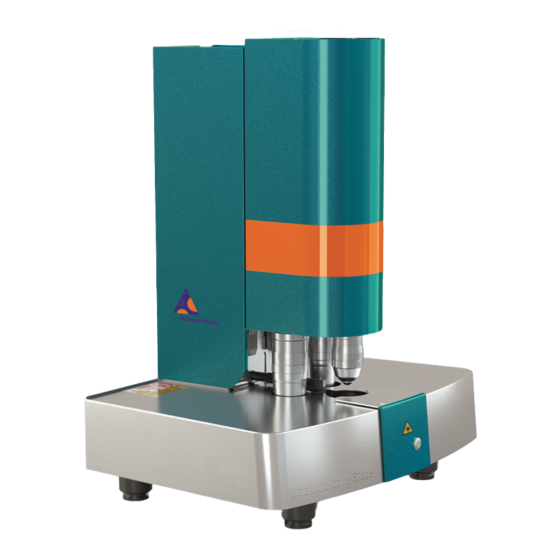
Miltenyi Biotec. The operating, maintenance, and servicing instructions described in this manual must be observed. The UltraMicroscope Blaze is for research use only in a laboratory environment. It is to be used by laboratory professional users only. Figure 2.1: Front view of the UltraMicroscope Blaze. - Page 18 Figure 2.2: Rear view of the UltraMicroscope Blaze. Figure 2.3: Detail view of the I/O ports and power switch.
- Page 19 Figure 2.4: Jog wheel for moving the sample arm in 3 dimensions (x, y, z) and sensitivity.
-
Page 21: Installation
Installation Components The Ultramicroscopes Blaze Beam Combiner and White Light Laser are delivered with lasers, lenses, and emission filters, as specified when ordering the instrument ( Table 3.1 ). Additional accessories ( Table 3.2 ) and Table 3.3 ) developed specifically for the system are available separately. For details visit consumables ( www.miltenyibiotec.com or contact your local sales representative. -
Page 22: Accessories
Various accessories Alignment tool for UltraMicroscope Blaze 150-001-813 Sample holder set for UltraMicroscope Blaze 150-001-814 Cuvette for UltraMicroscope Blaze 150-001-673 Table 3.2: Optional accessories available for the UltraMicroscope Blaze. Consumables Consumables Order no. MACS Clearing Kit 130-126-719 MACS Imaging Solution 130-126-335 Table 3.3: Consumables that have to ordered separately. -
Page 23: Unpacking And Installation
Protect the instrument from shock and vibration. Do not place vibrating devices on (e.g. vortex mixers) on the same table as the UltraMicroscope Blaze. This could impair the quality of the results. Only Milteny Biotec service personnel is allowed to unpack and install the instrument. Please contact Miltenyi Biotec Technical Support for further information. -
Page 25: Switching On And Off
2 Switch on the external laser module. The key switch is located on the laser module (see manufacturer documentation). 3 Switch on the UltraMicroscope Blaze. The power switch is located on the rear side of the instrument ( Figure 2.2 ). - Page 26 Name Function Location Adjust window/live Adjusts the contrast based on the region Live Window of interest in the Live Window ROI for active profile Defines a region of interest in the Live Live Window Window Light sheet focus Turns on the light sheet focus in the Live Live Window Window Show crosshairs...
-
Page 27: Preparing The Instrument
Preparing the instrument BIOLOGICAL HAZARD Contamination or infection may lead to severe personal injury or death, depending on the used material. • Take care when handling samples and reagents. • To avoid spilling of liquids, wipe all parts of the instrument (e.g. objectives, cuvette) with a soft, lint-free disposable tissue. - Page 28 4 Remove the cuvette by lifting it from its magnectic holders. 5 Fill the cuvette about three quarters with the selected imaging buffer. 6 Place the cuvette on its magnetic holders again. Be careful not to spill any buffer. 7 Make sure that the cuvette is securely placed on the magnetic holders. 8 Reattach the sample arm by tightening the thumb screw again.
-
Page 29: Laser Alignment
( plane. Screws z2 and z4 are used for aligning the three beams of each light sheet. Figure 6.1: Bottom view of the UltraMicroscope Blaze with the positions of the adjustable precision screws. Setting the beam path 1 Switch on the instrument as described under Switching on the instrument on page 25 . - Page 30 4 Raise the cuvette by pressing the button on the drawer. Close the drawer ( Figure 6.2 ). Figure 6.2: UltraMicroscope Blaze with open drawer. 5 Select the excitation and emission wavelengths for the alignment tool (488 nm or 561 nm excitation) under Channel Setup in the Settings 1 window.
- Page 31 8 Make sure the cuvette is in a centered position. Move the alignment tool until the beams on the right side pass through the tool and form three thin lines on the other side of the pinhole foil. 9 Select the 1.1× objective lens ( LVBT 1× ) with 1.0× zoom and the medium used in Optical Setup . 10 Adjust the Laser Transmission Control until the three beams passing the pinhole can easily be detected while the other side of the pinhole is not saturated.
- Page 32 15 Select the Advanced tab in the Settings 1 window. Always start with the center beam on the right-hand side. It is the reference beam and cannot be adjusted by the user. Click Light Sheet Configuration > Enable only the central beam to activate the center beam. 16 If two laser beams are visible passing the mask ( Figure 6.3;...
- Page 33 Adjusting the horizontal focus 1 To adjust the horizontal focus, select the Calibration tab on the bottom of the Settings 1 window. 2 Move the slider Light Sheet Focus > Offset Calibration until only one beam passes through the pinhole. Ensure the horizontal focus is always in the center and the Light Sheet Properties >...
-
Page 34: Adjustment Of The Lateral Beams On The Right-Hand Side
Adjustment of the lateral beams on the right-hand side To adjust the lateral beams on the right-hand side, the horizontal focus must not be changed. 1 Click Light Sheet Configuration > Disable the central beam in the Advanced tab to activate the lateral beams. -
Page 35: Adjustment Of The Lateral Beams On The Left-Hand Side
2 Click Light Sheet Configuration > Enable only the central beam in the Settings > Advanced tab to activate the center beam. 3 Ensure that the slider for the horizontal focus is still in the center. If necessary, adjust the position. 4 Adjust the height with the adjustment screw ( Figure 6.1;... - Page 36 4 Click Light Sheet Configuration > Enable all three beams to activate all beams in the Advanced tab. Now all three laser beams pass through the pinhole in the center of the mask of the alignment tool. If the alignment of the left-hand side to the right-hand side is not successful, check the positioning of the cuvette again.
-
Page 37: Setting Up An Experiment
Setting up an experiment Capturing a single-color z-stack 7.1.1 Aligning the sample 1 Start the ImSpectorPro software. 2 Select Instrument Mode > Ultramicroscope in the Measurement Wizard window. 3 Select Measurement Mode > Acquisition for measuring a z-stack. 4 Select xyz-Table Z in the Devices list. Check Split only if you want to generate seperate files for each color. - Page 38 5 Click the Autosave button at the end of the row under AS . It will turn green. 6 Click the Autosave Settings to select the storage location. 7 Select the appropriate objective Optical Setup > Objective , the zoom Optical Setup > Zoom and the Optical Setup >...
-
Page 39: Optimizing The Measurement Settings
11 Click and hold the Objective Lens Focus > Move Objective to Measurement button to move down the motorized turret. The objective will automatically stop. 12 Click the Show crosshairs button on the right side of the live window to activate the crosshairs. 13 Use the jog wheel to move the sample inside the cuvette until the surface of the sample is visible in the center of the crosshairs. -
Page 40: Capturing An Image
The settings described may need to be adjusted when the zoom settings are changed. 7.1.3 Capturing an image 1 Move in the z-direction to your starting position. 2 Click Current Position > Set as Zero and Scan Range > Start > Take in the Settings 2 window. 3 Move through the sample until you reach the end of the z-stack and click Scan Range >... - Page 41 3 Click the Autosave button under AS . It will turn green. Check Split only if you want to generate seperate files for each color. 4 Select the right excitation and emission wavelengths for your sample under Filter for Measurement in Settings 1 window.
-
Page 42: Capturing A Mosaic Image
Capturing a mosaic image 1 Select Measurement Mode > Mosaic Aquisition in the Measurement Wizard . 2 Click the Mosaic bar in the xyz-Table Visual XY window. 3 Double-click the Green Square representing the field of view. The square will turn grey. - Page 43 4 Click and drag the Black Dots at the edges to create a mosaic. 5 Enter a percentage value to set an Overlap . 6 To start the measurement, proceed as described under Capturing an image on page 40...
-
Page 45: Maintenance
Maintenance Servicing Service the instrument every 12 months. Contact Miltenyi Biotec for support. Cleaning the instrument ELECTRICITY Electric devices bear the risk of electric shock, short circuits, overheating, fire, and explosion. This may lead to burns, severe personal injury, or death. -
Page 47: Technical Data And Specifications
Specifications The safety of the instrument may be compromised if used outside its specifications. • Do not use the instrument outside its specifications. UltraMicroscope Blaze specifications General information Dimensions (w × d × h) 67 cm × 52.5 cm × 91 cm... - Page 48 1–6 Thickness 4–24 μm Width 1.5–20 mm Numerical aperture 0.0135–0.135 Focus positioning Dynamic Table 9.1: UltraMicroscope Blaze specifications Camera specifications Detector 4.2 Mpx sCMOS camera 5.5 Mpx sCMOS camera Active pixels (w × h) 2048×2048 2560×2160 Pixel size 6.5 μm × 6.5 μm 6.5 μm ×...
-
Page 49: Ec / Eu Declaration Of Conformity
EC / EU Declaration of Conformity This declaration of conformity is issued under the sole responsibility of the manufacturer: LaVision BioTec GmbH - A Miltenyi Biotec Company Astastraße 14 33617 Bielefeld Germany The declaration of conformity refers to the machinery identified as follows:... -
Page 51: Technical Support
Technical support For technical support, contact your local Miltenyi Biotec representative or Miltenyi Biotec Technical Support at Miltenyi Biotec headquarters: Miltenyi Biotec B.V. & Co. KG Friedrich-Ebert-Straße 68 51429 Bergisch Gladbach Germany Phone: +49 2204 8306 3803 Fax +49 2204 8306-89 Email: technicalsupport@miltenyi.com... -
Page 53: Legal Notes
VOID AND CANCEL ALL WARRANTIES WITH RESPECT TO THE AFFECTED PRODUCT. Miltenyi Biotec’s warranty does not cover products sold AS IS or WITH ALL FAULTS, or which had its serial number defaced, altered, or removed, or any consumables or parts identified as being supplied by a third party. -
Page 54: Trademarks
Miltenyi Biotec's option, to make repairs, replacements, or corrections to the product or any component thereof as may be required to restore the full usability of your product. If Miltenyi Biotec determines that a product for which you have requested warranty services is not covered by the warranty hereunder, you shall pay or reimburse Miltenyi Biotec for all costs of investigating and responding to such request at Miltenyi Biotec’s then... - Page 56 Miltenyi Biotec provides products and services worldwide. Visit www.miltenyibiotec.com/local to find your nearest Miltenyi Biotec contact. Unless otherwise specifically indicated, Miltenyi Biotec products and services are for research use only and not for therapeutic or diagnostic use. Blaze, MACS, and the Miltenyi Biotec logo are registered trademarks or trademarks of Miltenyi Biotec and/or its affiliates in various countries worldwide.
Need help?
Do you have a question about the UltraMicroscope Blaze and is the answer not in the manual?
Questions and answers